Componentlevel design What is Component A component is


![where a [guard condition] is written in Object Constraint Language (OCL)5 and specifies any](https://slidetodoc.com/presentation_image_h2/c9275d6c820373495d93773102f967a7/image-14.jpg "where a [guard condition] is written in Object Constraint Language (OCL)5 and specifies any")


 and identify the classes")


- Slides: 21
Component-level design: What is Component: A component is a modular building block for computer software. More formally, the Unified Modeling Language Specification defines a component as “. . . a modular, deployable, and replaceable part of a system that encapsulates implementation and exposes a set of interfaces. ” Components populate the software architecture and play a role in achieving the objectives and requirements of the system to be built. Because components reside within the software architecture, they must communicate and collaborate with other components and with entities (e. g. , other systems, devices, people) that exist outside the boundaries of the software. The true meaning of the term component will differ depending on the point of view of the software engineer who uses it. In the sections that follow, I examine three important views of what a component is and how it is used as design modeling proceeds.
An Object-Oriented View In the context of object-oriented software engineering, a component contains a set of collaborating classes. Each class within a component has been fully elaborated to include all attributes and operations that are relevant to its implementation. As part of the design elaboration, all interfaces that enable the classes to communicate and collaborate with other design classes must also be defined. To accomplish this, you begin with the requirements model and elaborate analysis classes (for components that relate to the problem domain) and infrastructure classes (for components that provide support services for the problem domain).
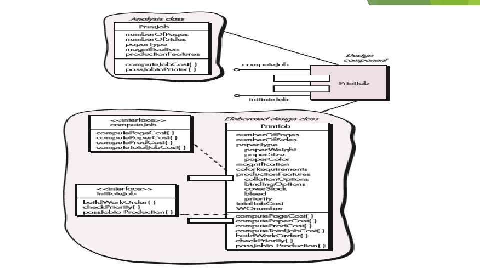
To illustrate this process of design elaboration, consider software to be built for a sophisticated print shop. The overall intent of the software is to collect the customer’s requirements at the front counter, cost a print job, and then pass the job on to an automated production facility. During requirements engineering, an analysis class called Print. Job was derived. The attributes and operations defined during analysis are noted at the top of Figure 10. 1. During architectural design, Print. Job is defined as a component within the software architecture and is represented using the shorthand UML notation 2 shown in the middle right of the figure. Note that Print. Job has two interfaces, compute. Job, which provides job costing capability, and initiate. Job, which passes the job along to the production facility. These are represented using the “lollipop” symbols shown to the left of the component box. Component-level design begins at this point. The details of the component Print. Job must be elaborated to provide sufficient information to guide implementation. The original analysis class is elaborated to flesh out all attributes and operations required to implement the class as the component Print. Job. Referring to the lower right portion of Figure 10. 1, the elaborated design class Print. Job contains more detailed attribute information as well as an expanded description of operations required to implement the component. The interfaces compute. Job and initiate. Job imply communication and collaboration with other components (not shown here). For example, the operation compute. Page. Cost() (part of the compute. Job interface) might collaborate with a Pricing. Table component that contains job pricing information. The check. Priority() operation (part of the initiate. Job interface) might collaborate with a Job. Queue component to determine the types and priorities of jobs currently awaiting production. This elaboration activity is applied to every component defined as part of the architectural design. Once it is completed, further elaboration is applied to each attribute, operation, and interface. The data structures appropriate for each attribute must be specified.
The Traditional/Conventional View In conventional view, the component can be defined as a functional element of a program that consists of i. Processing logic ii. Internal data structure which are necessary for implementing the processing logic iii. An interface that enables the invocation of components iv. Data that is to be passed between the components Generally component is also referred to as a module that is present in software architecture. This module acts as any one of the following component: 1. Control Component: This module is for coordinating the invocation of the problem domain components. 2. Problem Domain Component: This module is responsible for implementing entire or partial function which is required by the customer. 3. Infrastructure Component: This module is responsible for invoking the functions, which support the processing performed in problem domain component. The conventional software component is derived from the analysis model, whose data flow elements are used as the underlying concept for the derivation. Let us consider an example of xerox center in order to understand of design elaboration.
A Process-Related View Process-related view performs the component level design using the existing software components. That is unlike object-oriented and conventional views, process related view does not design the component from the scratch. While the architecture of component is being developed software engineers use the catalog of the existing design for selecting the design patterns. As the components are designed by considering the eras ability factor, the designer have complete information about, i. Interface of component ii. Function of component iii. Communication and collaboration between the components.
Designing Class-Based Components When an object-oriented software engineering approach is chosen, component-level design focuses on the elaboration of problem domain specific classes and the definition and refinement of infrastructure classes contained in the requirements model. The detailed description of the attributes, operations, and interfaces used by these classes is the design detail required as a precursor to the construction activity. Basic Design Principles : The Open-Closed Principle (OCP). “A module [component] should be open for extension but closed for modification. (if it is extended there are no internal modifications performed to the components) The Liskov Substitution Principle (LSP). “Subclasses should be substitutable for their base classes. Dependency Inversion Principle (DIP). “Depend on abstractions. Do not depend on concretions. ” (The higher level modules and lower level modules must abstraction dependent i. e the modules of higher level should not rely on the modules of lower level. ) The Interface Segregation Principle (ISP). “Many client-specific interfaces are better than one general purpose interface. (the dependency relation ship that exists between the classes must rely on the smallest possible interface) The Release Reuse Equivalency Principle (REP). “The granule of reuse is the granule of release. ” (The components released by a monitoring system are the one’s that have the capability of being reused efficiently) The Common Closure Principle (CCP). “Classes that change together belong together. ” (changes made to one class result in changing all the other classes) The Common Reuse Principle (CRP). “Classes that aren’t reused together should not be grouped together. ” (if a class defined in a package is reused then all the other classes within the same package must also be reused.
Component-Level Design Guidelines Component level design can be efficiently performed if the designer follow certain guidelines which are applicable to components, their interfaces and the dependencies and inheritance. Guidelines Applicable to Components: 1. The components must be provided with their naming conventions, which are specified while designing and alter refined as well as elaborated during the design of component level model. 2. The component names in architectural model must be selected from the problem domain. 3. The component names must have a meaning so that they can be easily understood by the stake holders. Guidelines for Applicable to Interface: 1. If an interface is represented using lollipop approach it must be used in conjunction with formal UML box. 2. If an interface needs to be consistent, then flow of interface must be from the left hand side of the component box. 3. If an interface is relevant to a component being designed then only that interface needs to be displayed irrespective of other available interfaces. Guidelines for Applicable to Dependencies and Inheritance: 1. The dependencies must be moduled from left to right and the inheritance must moduled from bottom to top in order to achieve better readability. 2. The dependencies between the components must be represented using interfaces.
Cohesion Within the context of component-level design for object-oriented systems, cohesion implies that a component or class encapsulates only attributes and operations that are closely related to one another and to the class or component itself. Lethbridge and Laganiére define a number of different types of cohesion (listed in order of the level of the cohesion 4): Functional: Exhibited primarily by operations, this level of cohesion occurs when a component performs a targeted computation and then returns a result. Layer: Exhibited by packages, components, and classes, this type of cohesion occurs when a higher layer accesses the services of a lower layer, but lower layers do not access higher layers. Consider, for example, the Safe Home security function requirement to make an outgoing phone call if an alarm is sensed. It might be possible to define a set of layered packages as shown in Figure 10. 5. The shaded packages contain infrastructure components. Access is from the control panel package downward. Communicational: All operations that access the same data are defined within one class. In general, such classes focus solely on the data in question, accessing and storing it.
Coupling is a qualitative measure of the degree to which classes are connected to one another. As classes (and components) become more interdependent, coupling increases. An important objective in component-level design is to keep coupling as low as is possible. Lethbridge and Laganiére define the following coupling categories: Content coupling: Occurs when one component “surreptitiously modifies data that is internal to another component”. This violates information hiding—a basic design concept. Common coupling: Occurs when a number of components all make use of a global variable. Although this is sometimes necessary (e. g. , for establishing default values that are applicable throughout an application), common coupling can lead to uncontrolled error propagation and unforeseen side effects when changes are made. Control coupling: Occurs when operation A() invokes operation B() and passes a control flag to B. The control flag then “directs” logical flow within B. The problem with this form of coupling is that an unrelated change in B can result in the necessity to change the meaning of the control flag that A passes. If this is overlooked, an error will result. Stamp coupling: Occurs when Class. B is declared as a type for an argument of an operation of Class. A. Because Class. B is now a part of the definition of Class. A, modifying the system becomes more complex. Data coupling: Occurs when operations pass long strings of data arguments. The “bandwidth” of communication between classes and components grows and the complexity of the interface increases. Testing and maintenance are more difficult.
Routine call coupling: Occurs when one operation invokes another. This level of coupling is common and is often quite necessary. However, it does increase the connectedness of a system. Type use coupling: Occurs when component A uses a data type defined in component B (e. g. , this occurs whenever “a class declares an instance variable or a local variable as having another class for its type” [Let 01]). If the type definition changes, every component that uses the definition must also change. Inclusion or import coupling: Occurs when component A imports or includes a package or the content of component B. External coupling: Occurs when a component communicates or collaborates with infrastructure components (e. g. , operating system functions, database capability, telecommunication functions). Although this type of coupling is necessary, it should be limited to a small number of components or classes within a system.
Conducting Component –Level Design The following steps represent a typical task set for component-level design, when it is applied for an object-oriented system. Step 1. Identify all design classes that correspond to the problem domain: Using the requirements and architectural model, each analysis class and architectural component is elaborated as described in Section 10. 1. 1. Step 2. Identify all design classes that correspond to the infrastructure domain: These classes are not described in the requirements model and are often missing from the architecture model, but they must be described at this point. As we have noted earlier, classes and components in this category include GUI components (often available as reusable components), operating system components, and object and data management components. Step 3. Elaborate all design classes that are not acquired as reusable components: Elaboration requires that all interfaces, attributes, and operations necessary to implement the class be described in detail. Design heuristics (e. g. , component cohesion and coupling) must be considered as this task is conducted. Step 3 a. Specify message details when classes or components collaborate: The requirements model makes use of a collaboration diagram to show analysis classes collaborate with one another. As component-level design proceeds, it is sometimes useful to show the details of these collaborations by specifying the structure of messages that are passed between objects within a system. Although this design activity is optional, it can be used as a precursor to the specification of interfaces that show components within the system communicate and collaborate. Figure 10. 6 illustrates a simple collaboration diagram for the printing system discussed earlier. Three objects, Production. Job, Work. Order, and Job. Queue, collaborate to prepare a print job for submission to the production stream. Messages are passed between objects as illustrated by the arrows in the figure. During requirements modeling the messages are specified as shown in the figure. However, as design proceeds, each message is elaborated by expanding its syntax in the following manner [Ben 02]: [guard condition] sequence expression (return value) : message name (argument list)
where a [guard condition] is written in Object Constraint Language (OCL)5 and specifies any set of conditions that must be met before the message can be sent; sequence expression is an integer value (or other ordering indicator, e. g. , 3. 1. 2) that indicates the sequential order in which a message is sent; (return value) is the name of the information that is returned by the operation invoked by the message; message name identifies the operation that is to be invoked, and (argument list) is the list of attributes that are passed to the operation. Step 3 b. Identify appropriate interfaces for each component: Within the context of component-level design, a UML interface is “a group of externally visible (i. e. , public) operations. The interface contains no internal structure, it has no attributes, no associations. . . ” [Ben 02]. Stated more formally, an interface is the equivalent of an abstract class that provides a controlled connection between design classes. The elaboration of interfaces is illustrated in Figure 10. 1. In essence, operations defined for the design class are categorized into one or more abstract classes. Every operation within the abstract class (the interface) should be cohesive; that is, it should exhibit processing that focuses on one limited function or subfunction.
Referring to Figure 10. 1, it can be argued that the interface initiate. Job does not exhibit sufficient cohesion. In actuality, it performs three different subfunctions— building a work order, checking job priority, and passing a job to production. The interface design should be refactored. One approach might be to reexamine the design classes and define a new class Work. Order that would take care of all activities associated with the assembly of a work order. The operation build. Work. Order() becomes a part of that class. Similarly, we might define a class Job. Queue that would incorporate the operation check. Priority(). A class Production. Job would encompass all information associated with a production job to be passed to the production facility. The interface initiate. Job would then take the form shown in Figure 10. 7. The interface initiate. Job is now cohesive, focusing on one function. The interfaces associated with Production. Job, Work. Order, and Job. Queue are similarly single-minded.
Step 3 c. Elaborate attributes and define data types and data structures required to implement them. In general, data structures and types used to define attributes are defined within the context of the programming language that is to be used for implementation. UML defines an attribute’s data type using the following syntax: name : type-expression initial-value {property string} where name is the attribute name, type expression is the data type, initial value is the value that the attribute takes when an object is created, and property-string defines a property or characteristic of the attribute. During the first component-level design iteration, attributes are normally described by name. Referring once again to Figure 10. 1, the attribute list for Print. Job lists only the names of the attributes. However, as design elaboration proceeds, each attribute is defined using the UML attribute format noted. For example, paper. Typeweight is defined in the following manner: paper. Type-weight: string “A” { contains 1 of 4 values - A, B, C, or D} which defines paper. Type-weight as a string variable initialized to the value A that can take on one of four values from the set {A, B, C, D}. If an attribute appears repeatedly across a number of design classes, and it has a relatively complex structure, it is best to create a separate class to accommodate the attribute.
Step 3 d. Describe processing flow within each operation in detail. This may be accomplished using a programming language-based pseudocode or with a UML activity diagram. Each software component is elaborated through a number of iterations that apply the stepwise refinement concept (Chapter 8). The first iteration defines each operation as part of the design class. In every case, the operation should be characterized in a way that ensures high cohesion; that is, the operation should perform a single targeted function or subfunction. The next iteration does little more than expand the operation name. For example, the operation compute. Paper. Cost() noted in Figure 10. 1 can be expanded in the following manner: compute. Paper. Cost (weight, size, color): numeric This indicates that compute. Paper. Cost() requires the attributes weight, size, and color as input and returns a value that is numeric (actually a dollar value) as output.
Step 4. Describe persistent data sources (databases and files) and identify the classes required to manage them. Databases and files normally transcend the design description of an individual component. In most cases, these persistent data stores are initially specified as part of architectural design. However, as design elaboration proceeds, it is often useful to provide additional detail about the structure and organization of these persistent data sources. Step 5. Develop and elaborate behavioral representations for a class or component. UML state diagrams were used as part of the requirements model to represent the externally observable behavior of the system and the more localized behavior of individual analysis classes. During component-level design, it is sometimes necessary to model the behavior of a design class. The dynamic behavior of an object (an instantiation of a design class as the program executes) is affected by events that are external to it and the current state (mode of behavior) of the object. To understand the dynamic behavior of an object, you should examine all use cases that are relevant to the design class throughout its life. These use cases provide information that helps you to delineate the events that affect the object and the states in which the object resides as time passes and events occur. The transitions between states (driven by events) are represented using a UML statechart [Ben 02] as illustrated in Figure 10. 9. The transition from one state (represented by a rectangle with rounded corners) to another occurs as a consequence of an event that takes the form: Event-name (parameter-list) [guard-condition] / action expression
Step 6. Elaborate deployment diagrams to provide additional implementation detail. Deployment diagrams (Chapter 8) are used as part of architectural design and are represented in descriptor form. In this form, major system functions (often represented as subsystems) are represented within the context of the computing environment that will house them. During component-level design, deployment diagrams can be elaborated to represent the location of key packages of components. However, components generally are not represented individually within a component diagram. The reason for this is to avoid diagrammatic complexity. In some cases, deployment diagrams are elaborated into instance form at this time. This means that the specific hardware and operating system environment(s) that will be used is (are) specified and the location of component packages within this environment is indicated. Step 7. Refactor every component-level design representation and always consider alternatives. Throughout this book, I have emphasized that design is an iterative process. The first component-level model you create will not be as complete, consistent, or accurate as the nth iteration you apply to the model. It is essential to refactor as design work is conducted.
Component-level Design for WEBAPPS In the context of this chapter, a Web. App component is (1) a well-defined cohesive function that manipulates content or provides computational or data processing for an end user or (2) a cohesive package of content and functionality that provides the end user with some required capability. Therefore, component-level design for Web. Apps often incorporates elements of content design and functional design. Content Design at the Component Level: Content design at the component level focuses on content objects and the manner in which they may be packaged for presentation to a Web. App end user. As an example, consider a Web-based video surveillance capability within Safe. Home. Assured. com. Among many capabilities, the user can select and control any of the cameras represented as part of a floor plan, require video-capture thumbnail images from all the cameras, and display streaming video from any one camera. In addition, the user can control pan and zoom for a camera using appropriate control icons. A number of potential content components can be defined for the video surveillance capability: (1) the content objects that represent the space layout (the floor plan) with additional icons representing the location of sensors and video cameras (2) the collection of thumbnail video captures (each a separate data object), and (3) the streaming video window for a specific camera. Each of these components can be separately named and manipulated as a package.
Functional Design at the Component Level: Modern Web applications deliver increasingly sophisticated processing functions that (1) (2) perform localized processing to generate content and navigation capability in a dynamic fashion, provide computation or data processing capability that is appropriate for the Web. App’s business domain, (3) provide sophisticated database query and access, or (4) establish data interfaces with external corporate systems. To achieve these (and many other) capabilities, you will design and construct Web. App functional components that are similar in form to software components for conventional software. Web. App functionality is delivered as a series of components developed in parallel with the information architecture to ensure that they are consistent. In essence you begin by considering both the requirements model and the initial information architecture and then examining how functionality affects the user’s interaction with the application, the information that is presented, and the user tasks that are conducted. During architectural design, Web. App content and functionality are combined to create a functional architecture. A functional architecture is a representation of the functional domain of the Web. App and describes the key functional components in the Web. App and how these components interact with each other.