Complex Amalgam Restorations Syed Mukhtar Un Nisar Andrabi

Complex Amalgam Restorations Syed Mukhtar Un Nisar Andrabi

Introduction • Complex posterior restorations are used to replace missing tooth structure of teeth that have fractured or are severely involved with caries or existing restorative material. • These restorations usually involve the replacement of one or more missing cusps.

Indications • Complex posterior amalgam restorations should be considered when: – large amounts of tooth structure are missing – one or more cusps need capping – increased resistance and retention forms are needed

Indications • Control restorations in teeth that have a questionable pulpal and/or periodontal prognosis, • Control restorations in teeth with acute and severe caries, • Definitive final restorations due to economics or age of the patient • Foundations

Contraindications • The complex amalgam restoration may be contraindicated if : – the patient has significant occlusal problems – the tooth cannot be properly restored with a direct restoration because of anatomic and/or functional considerations – the area to be restored is aesthetically important for the patient

Types of complex amalgam restorations • Pin-Retained Amalgam Restorations • Slot-Retained Amalgam Restorations • Amalgam Foundations.

Advantages • • Conservation of tooth structure Appointment time Resistance and retention form Economics

Disadvantages • • • Dentinal micro fractures Lowered fractured resistance Strength of amalgam restoration is reduced Micro leakage Perforations Difficulty to achieve proper contours

PIN RETAINED RESTORATIONS

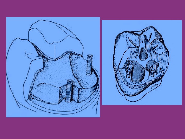
Definition • A pin retained restoration may be defined as any restoration requiring the placement of one or more pins in the dentin to provide adequate resistance and retention forms. • Pins are used whenever adequate resistance and retention forms cannot be established with slots, locks, or undercuts only. • The pin-retained amalgam is an important adjunct in the restoration of teeth with extensive caries or fractures.

Types of Pins 1. Cemented pins 2. Friction locked pins 3. Self threaded pins

CEMENTED PINS • Developed by Dr. Markley to retain large amalgam restorations • Made of Stainless Steel • They are cemented into pinholes prepared 0. 001 to 0. 002 inch (0. 025 to 0. 05 mm) larger than the diameter of the pin. • They are used to build foundation after endodontic treatment as they produce the least amount of stress • Offer less resistance than the other pins

FRICTION LOCKED PINS • Developed by Dr. Goldstein in 1966 • Made of stainless steel • More retentive than cemented pins • Used in vital teeth with good access and ease of tapping the pins • Cause craze lines or cracks

SELF THREADED PINS • Developed by Dr. Going in 1966 • Most popular type among all the different type of pins and extensively used • Made of stainless steel or titanium pins • Provide maximum retention among all types of pins • Cause craze lines • Used in vital teeth

CEMENTED PINS FRICTION LOCKED SELF THREADED PINS Stainless steel with threads or serrations threads Stainless steel/Titanium with gold plating Pin channel [0. 020” to 0. 32”] larger than pin size [0. 018” to 0. 30”] Pin channel is 0. 001” Pin channel is 0. 015” smaller than pin size to 0. 004” smaller than pin size Luted with standard luting agents Taped into place with Placed by hand mallet wrench or contra angle hand piece Ease of placement Pin placement is difficult Pin placement is easy

CEMENTED PINS FRICTION LOCKED PINS SELF THREADED PINS Less internal stresses Increased internal stresses but less as compared to friction locked pins Least retentive 2 -3 times more retentive than cemented pins 5 -6 times more retentive than friction locked pins

Factors Affecting the Retention of the Pin in Dentin and Amalgam • Type • Surface characteristics. – The number and depth of the elevations (serrations or threads) on the pin. • Orientation, number, and diameter. – Placing pins in a nonparallel manner increases their retention – Bending of pins is not desirable – Increasing the number of pins increases the retention in dentin and amalgam • Extension into dentin and amalgam – Pin extension into dentin and amalgam greater than 2 mm is unnecessary for pin retention and is contraindicated to preserve the strength of the dentin and the amalgam.
 • It is the most widely used self-threading pin because")
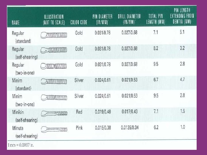
Thread Mate System (TMS) • It is the most widely used self-threading pin because of its: 1. Versatility of design 2. Wide range of pin sizes 3. Colour coding system, 4. Greater retentiveness 5. Gold plated surface finish, which may eliminate the possibility of corrosion
 and depth limiting (b).")
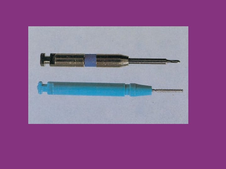
Two types of Kodex twist drills: standard (a) and depth limiting (b).

PIN PLACEMENT FACTORS AND TECHNIQUES

Pin size : • Two determining factors for selecting pin size: – the amount of dentin available – the amount of retention desired. – the pins of choice for severely involved posterior teeth are the Minikin (0. 019 inch [0. 48 mm]) and, occasionally, the Minim (0. 024 inch [0. 61 mm]). • Of the four pin sizes, the Regular pin caused the highest incidence of dentinal cracking that communicated with the pulp chamber. (Webb EL, Straka WF, Phillips CL. J Prosthet Dent 61(5): 624 -628, 1989. )

Number of pins. • Several factors must be considered when deciding how many pins are required: – the amount of missing tooth structure, – the amount of dentin available to receive pins safely, – the amount of retention required, and – the size of the pins. • As a rule, one pin per missing axial line angle should be used.
 knowledge of")
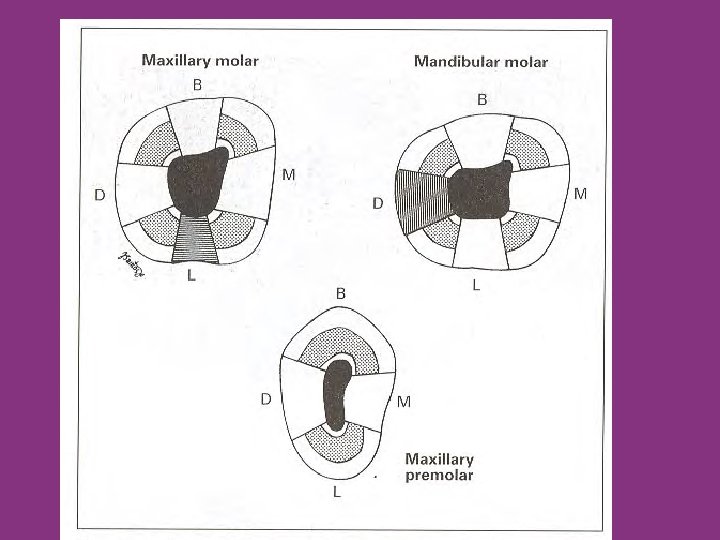
Location of pins • Factors that aid in determining pinhole locations: (1) knowledge of normal pulp anatomy and external tooth contours, (2) a current radiograph of the tooth, (3) a periodontal probe, and (4) the patient's age

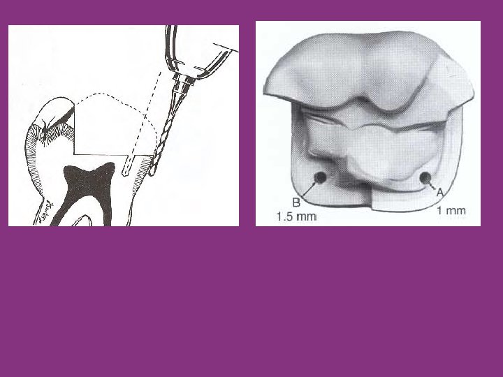
Location of pins • Pinholes should be located near the line angles of the tooth, • The pinhole should be parallel to the adjacent external surface of the tooth. • Pinholes should be located halfway between the pulp and the DEJ or external surface of the tooth root • The pinhole should be positioned no closer than 0. 5 to 1 mm to the DEJ or no closer than 1 to 1. 5 mm to the external surface of the tooth, whichever distance is greater

The position of a pinhole must not be so close to a vertical wall of tooth structure that condensation of amalgam against the pin or wall is jeopardized. A recess should be prepared in such case.

Pinholes should be prepared on a flat surface that is perpendicular to the proposed direction of the pinhole. Whenever three or more pinholes are placed, they should be located at different vertical levels on the tooth, if possible

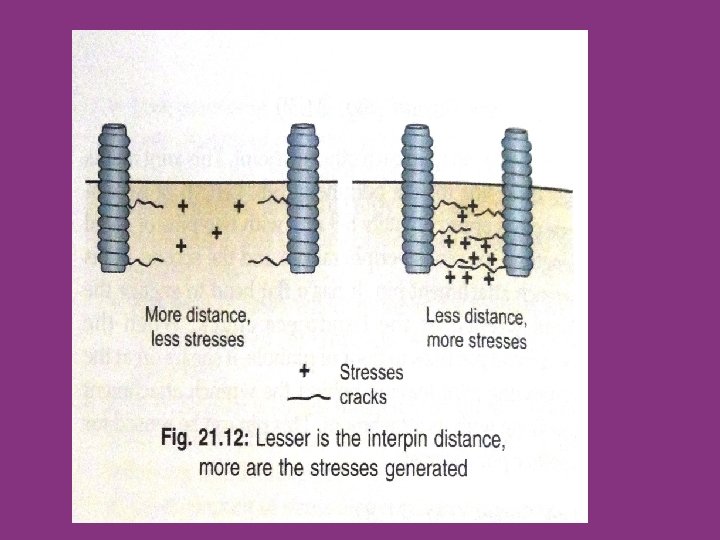
Inter-pin distance • Spacing between pins, or the interpin distance, must be considered when two or more pinholes are prepared. • The optimal interpin distance depends on the size of pin to be used. • The minimal interpin distance is 3 mm for the Minikin (0. 019 inch [0. 48 mm]) pin and 5 mm for the Minim (0. 024 inch [0. 61 mm]) pin. • Maximal interpin distance results in lower levels of stress in dentin

Pinhole preparation.

Pinhole preparation.
 should be used for preparing")
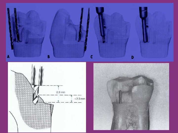
Pinhole Preparation • The Kodex drill (a twist drill) should be used for preparing pinholes • A depth-limiting drill should be used to prepare the hole – to achieve optimal depth of pin in dentin-2 mm • Prepare a hole on a flat surface that is perpendicular to the drill- only then the correct depth will be prepared.

Pinhole Preparation • Place the drill in the gingival crevice beside the location for the pinhole, position it until it lies flat against the external surface of the tooth, and then, • Without changing the angulation obtained from the crevice position, move the handpiece occlusally and place the drill in the previously prepared pilot hole • With the drill tip in its proper position and with the handpiece rotating at very low speed (300 to 500 rpm) apply pressure to the drill, and prepare the pinhole in one or two movements until the depth-limiting portion of the drill is reached, and remove the drill from the pinhole
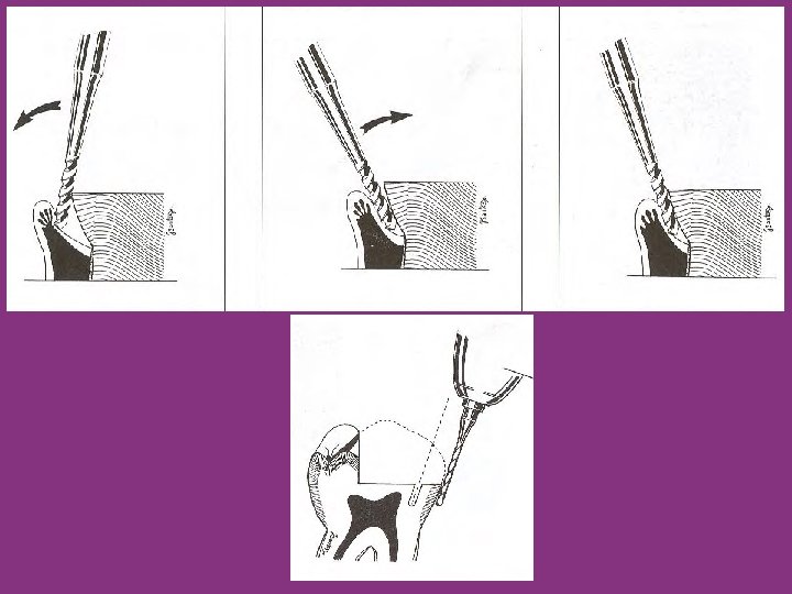

Pinhole Preparation • Certain clinical locations require extra care in determining pinhole angulation – Distal of mandibular molars and the lingual of maxillary molars – Teeth that are rotated in the arch – Teeth that are abnormally tilted in the arch- e. g Mesially tilted mandibular 2 nd molars.

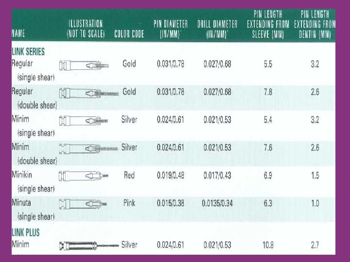
Pin Insertion. • Two instruments for insertion of threaded pins are available: • Conventional latch-type contra-angle handpiece – Recommended for the insertion of the Link Series and the Link Plus pins • TMS hand wrenches – Recommended for placement of standard pins.
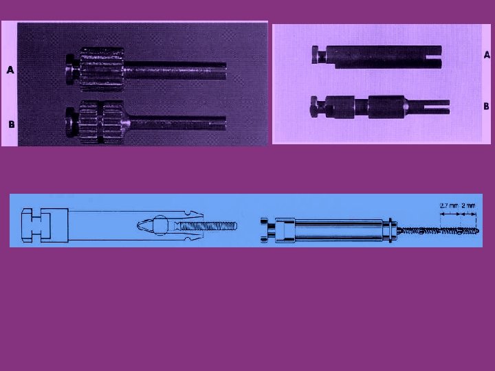

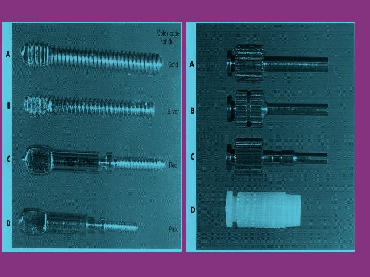
Five designs of TMS pins. A, Standard. B, Self-shearing. C, Two-in-one. D, Link Series. E, Link Plus

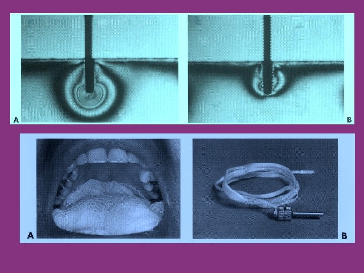
Pin Insertion. • A standard design pin is placed in the appropriate • wrench and slowly threaded clockwise into the pinhole until a definite resistance is felt when the pin reaches the bottom of the hole. • The pin should then be rotated one-quarter to one-half turn counterclockwise to reduce the dentinal stress created. • Use rubber dam isolation or use a throat shield and tie a floss to the pin.

• Once the pins are placed, evaluate their length • Any length greater than 2 mm should be removed- with a 1/2, round bur or 169 L bur held perpendicular to pin. • After placement, the pin should be tight, immobile, and not easily withdrawn.

• Using a mirror, view the preparation from all directions (particularly from the occlusal) to determine if any pins need to be bent to position them within the anticipated contour of the final restoration and to provide adequate bulk of amalgam between the pin and the external surface of the final restoration.
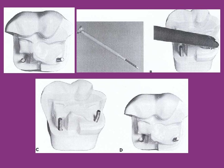

Placement of cemented pins. A. Prepare pinholes with appropriately sized twist drill. B. Cut proper length of pin with wire-cutting pliers. C. Slightly round the end of the pin with rotating carborundum disc. D. Place pins in tooth, and evaluate need for bending. E. Hold pin with two pairs of pliers, and bend as necessary. F. Pins bent. G. Convey cement into pinholes with a Lentulo spiral instrument. H. Pins cemented.

Failure of pin-retained restorations • The failure of pin-retained restorations might occur at any of five different locations: – Within the restoration (restoration fracture) – at the interface between the pin and the restorative material (pin-restoration separation) – within the pin (pin fracture), – at the interface between the pin and the dentin (pindentin separation) – Within the dentin (dentin fracture) • Failure is more likely to occur at the pin-dentin interface than at the pin-restoration interface

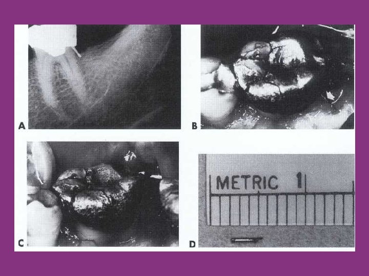
Procedural problems encountered • Broken drills and broken pins. • Loose pins. • Penetration into the pulp and perforation of the external tooth surface.

Pulpal Penetration/Perforation • A pulpal penetration is treated as any other small mechanical exposure. • Place a calcium hydroxide liner over the opening of the pinhole, and prepare another hole 1. 5 to 2 mm away. • Regardless of the method of treatment rendered, the patient must be informed of the perforation or pulpal penetration at the completion of the appointment.

Perforation of the external tooth surface. • Perforation of the external surface of the tooth can occur occlusal or apical to the gingival attachment. • Perforations that occur occlusal to the gingival attachment: 1) The pin can be cut off flush with the tooth surface and no further treatment rendered, 2) The pin can be cut off flush with the tooth surface and the preparation for a cast restoration extended gingivally beyond the perforation, 3) The pin can be removed, and the external aspect of the pinhole enlarged slightly and restored with amalgam.

Perforation of the external tooth surface. • Perforations that occur apical to the gingival attachment: 1) Reflect the tissue surgically, remove the necessary bone, enlarge the pinhole slightly, and restore with amalgam. 2) Perform a crown lengthening procedure, and place the margin of a cast restoration gingival to the perforation

SLOT-RETAINED AMALGAM RESTORATIONS.

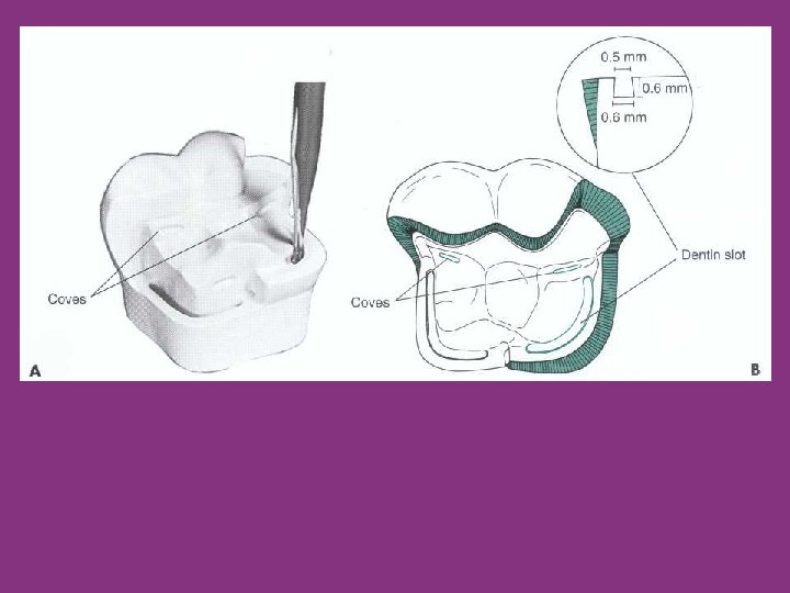
Slot-Retained Amalgam Restorations. • Slots are horizontally prapred channels in dentine. • The slot is at least 0. 5 mm in depth and 1 mm or more in length depending on the distance between the vertical walls • Slots are usually placed on the facial, lingual, mesial, and distal aspects of the preparation • The slot may be continuous or segmented, depending on the amount of missing tooth structure. • Shorter slots provide as much resistance to horizontal force as do longer slots. • Slots can be used in combination with pins to generate additional retention and resistance forms.
 bur is used to place a")
Slot preparation • A No. 33'/2 (Inverted cone) bur is used to place a slot in the gingival floor 0. 5 mm axial of the DEJ. • An alternative technique is to prepare the slot initially with a No. 169 L bur. Then, ensure its convergence by refining it with a No. 331/2 bur.

AMALGAM FOUNDATIONS

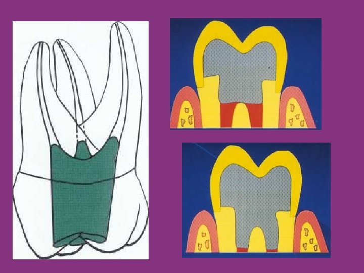
Amalgam Foundations • A foundation is an initial restoration of a severely involved tooth. The tooth is restored so that the restorative material (amalgam, composite, or other) will serve in lieu of tooth structure t provide retention and resistance forms during the development of the subsequent final cast restoration. • A foundation is indicated for a tooth that is severely broken down and lacks the resistance and retention forms needed for an indirect restoration • Foundations are placed in preparation for a full crown, especially in endodontically treated teeth.

Amalgam Foundations • The amalgam foundation restorations mainly rely on Chamber Retention. • If the height of available pulp chamber is 46 mm adequate retention can be gained by filling from the orifices. • If the height of available pulp chamber is 2 mm or less extension into the root canal space 2 to 4 mm is recommended

Thank you
- Slides: 69