Compiler analyzes the instructions before and after the

Compiler analyzes the instructions before and after the branch and rearranges the program sequence by inserting useful instructions in the delay steps
 Resource conflicts – memory access")
– Pipeline Conflicts : 3 major difficulties • 1) Resource conflicts – memory access by two segments at the same time • 2) Data dependency – when an instruction depend on the result of a previous instruction, but this result is not yet available • 3) Branch difficulties – branch and other instruction (interrupt, ret, . . ) that change the value of PC – Data Dependency • Hardware – Hardware Interlock » previous instruction Hardware Delay – Operand Forwarding » previous instruction, register » Software – Delayed Load » previous instruction No-operation instruction – Handling of Branch Instructions • Prefetch target instruction – Conditional branch: - branch target instruction (

• Prefetch Target Instruction –Fetch instructions in both streams, branch not taken and branch taken –Both are saved until branch is executed. Then, select the right instruction stream and discard the wrong stream • Branch Target Buffer(BTB; Associative Memory) –Entry: Addr of previously executed branches; Target instruction and the next few instructions –When fetching an instruction, search BTB. –If found, fetch the instruction stream in BTB; –If not, new stream is fetched and update BTB • Loop Buffer (High Speed Register file) – Storage of entire loop that allows to execute a loop without accessing memory • Branch Prediction –Guessing the branch condition, and fetch an instruction stream based on the guess. Correct guess eliminates the branch penalty • Delayed Branch –Compiler detects the branch and rearranges the instruction sequence by inserting useful instructions that keep the pipeline busy in the presence of a branch instruction

Mechanisms for Instruction Pipelining • Goal: Achieve maximum parallelism in pipeline by smoothening the instruction flow and minimizing the idle cycles • Mechanisms: – – Prefetch Buffers Multiple Functional Units Internal Data Forwarding Hazard Avoidance

Prefetch Buffers • Used to match the instruction fetch rate to the pipeline consumption rate • In a single memory access, a block of consecutive instructions are fetched into a prefetch buffer • Three types of prefetch buffers: – Sequential buffers, used to store sequential instructions – Target buffers, used to store branch target instructions – Loop buffer, used to store loop instructions

Multiple Functional Units • At times, a specific pipeline stage becomes the bottleneck • Identified by large number of checks in a row in reservation table • To resolve dependencies, we use reservation stations • Each RS is uniquely identified with a tag monitored by tag unit (Register Tagging) • Helps in conflict resolution and serving as buffer

Multifunctional Arithmetic Pipeline • Multifunctional arithmetic pipeline perform many functions • Types of multifunctional pipelines: – Static pipeline • Performs single function at a given time, another function at some other time – Dynamic pipeline • Performs multiple functions at the same time • Care needs to be taken in sharing the pipeline

• Example: Scientific Computer Static. Advanced Multifunctional Pipeline • Key features: – Four pipeline arithmetic units – Large number of working registers in the processor which controls operations of memory buffer units and arithmetic units – IPU handles fetching and decoding of instructions

Pipeline Interconnections Example: Advanced Scientific Computer Arithmetic pipeline has eight stages It is an example of static multifunctional pipeline With change in interconnections, different functions (fixed-point and floating point) can be performed

Performance Considerations • The execution time T of a program that has a dynamic instruction count N is given by: where S is the average number of clock cycles it takes to fetch and execute one instruction, and R is the clock rate. • Instruction throughput is defined as the number of instructions executed per second.

Overview • An n-stage pipeline has the potential to increase throughput by n times. • However, the only real measure of performance is the total execution time of a program. • Higher instruction throughput will not necessarily lead to higher performance. • Two questions regarding pipelining Ø How much of this potential increase in instruction throughput can be realized in practice? Ø What is good value of n?

“Iron Law” of Processor Time =Performance Instructions Cycles Time Program * Instruction * Cycle per program depends on source code, – Instructions compiler technology, and ISA – Cycles per instructions (CPI) depends upon the ISA and the microarchitecture – Time per cycle depends upon the microarchitecture and the base technology Microarchitecture Microcoded Single-cycle unpipelined Pipelined CPI >1 1 1 cycle time short long short 13

CPI Examples Microcoded machine 7 cycles 5 cycles Inst 1 Inst 2 10 cycles Time Inst 3 3 instructions, 22 cycles, CPI=7. 33 Unpipelined machine Inst 1 Inst 2 Inst 3 3 instructions, 3 cycles, CPI=1 Pipelined machine Inst 1 Inst 2 Inst 3 3 instructions, 3 cycles, CPI=1 14
 backed up by")
Technology Assumptions • A small amount of very fast memory (caches) backed up by a large, slower memory • Fast ALU (at least for integers) • Multiported Register files (slower!) A 5 -stage pipeline will be the focus of our detailed design - some commercial designs have over 30 pipeline stages to do an integer add! 15

Speed Up Equation for Pipelining For simple RISC pipeline, CPI = 1:
 • Machine B: Single ported")
Example… • Machine A: Dual ported memory (“Harvard Architecture”) • Machine B: Single ported memory, but its pipelined implementation has a 1. 05 times faster clock rate • Ideal CPI = 1 for both • Loads are 40% of instructions executed Speed. Up. A = Pipe. Depth/(1 + 0) x (clockunpipe/clockpipe) = Pipeline Depth Speed. Up. B = Pipe. Depth/(1 + 0. 4 x 1) x (clockunpipe/(clockunpipe / 1. 05) = (Pipe. Depth/1. 4) x 1. 05 = 0. 75 x Pipe. Depth Speed. Up. A / Speed. Up. B = Pipe. Depth/(0. 75 x Pipe. Depth) = 1. 33 • Machine A is 1. 33 times faster

Designing a Pipelined Processor What do we need to do to pipeline the process ? Instruction Fetch Instr. Decode Reg. Fetch Execute Addr. Calc Next SEQ PC Adder RS 1 WB Data L M D MUX Sign Extend Data Memory Imm ALU RD MUX Inst Memory Address RS 2 Zero? Reg File 4 Write Back MUX Next PC Memory Access

5 Steps of MIPS/DLX Datapath RD RD RD • Data stationary control – local decode for each instruction phase / pipeline stage MUX Data Memory Sign Extend Write Back MEM/WB MUX ALU Imm MUX RS 2 Zero? Reg File Memory Address RS 1 Next SEQ PC Memory Access EX/MEM Next SEQ PC ID/EX Adder 4 IF/ID Next PC Execute Addr. Calc Instr. Decode Reg. Fetch WB Data Instruction Fetch

Graphically Representing Pipelines • Can help with answering questions like:
 Ifetch DMem Reg ALU O r d e r")
Visualizing Pipelining Time (clock cycles) Ifetch DMem Reg ALU O r d e r Ifetch ALU I n s t r. ALU Cycle 1 Cycle 2 Cycle 3 Cycle 4 Cycle 5 Cycle 6 Cycle 7 Ifetch Reg Reg DMem Reg

nventional Pipelined Execution Represen Time IFetch Dcd Exec IFetch Dcd Mem WB Exec Mem WB Exec Mem IFetch Dcd Program Flow IFetch Dcd WB

ingle Cycle, Multiple Cycle, vs. Pipeline Cycle 1 Cycle 2 Clk Single Cycle Implementation: Load Store Waste Cycle 1 Cycle 2 Cycle 3 Cycle 4 Cycle 5 Cycle 6 Cycle 7 Cycle 8 Cycle 9 Cycle 10 Clk Multiple Cycle Implementation: Load Ifetch Reg Exec Mem Wr Reg Exec Mem Store Ifetch Reg Pipeline Implementation: Load Ifetch Reg Store Ifetch R-type Ifetch Reg Exec Wr Mem Wr Exec Mem R-type Ifetch

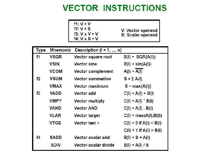
• Vector Processing – Science and Engineering Applications • Long-range weather forecasting, Petroleum explorations, Seismic data analysis, Medical diagnosis, Aerodynamics and space flight simulations, Artificial intelligence and expert systems, Mapping the human genome, Image processing – Vector Operations • Arithmetic operations on large arrays of numbers • Conventional scalar processor – Machine language Initialize I = 0 20 Read A(I) Read B(I) Store C(I) = A(I) + B(I) Increment I = I + 1 If I 100 go to 20 Continue • Vector processor – Single vector instruction C(1: 100) = A(1: 100) + B(1: 100) » Fortran language DO 20 I = 1, 100 20 C(I) = A(I) + B(I)

– Vector Instruction Format : ADD A B 100 – Matrix Multiplication • 3 x 3 matrices multiplication : n 2 = 9 inner product – : inner product 9 • Cumulative multiply-add operation : n 3 = 27 multiply-add C 11= 0 – : multiply-add C

– Pipeline for calculating an inner product : • Floating point multiplier pipeline : 4 segment • Floating point adder pipeline : 4 segment • – after 1 st clock input A 1 B 1 A 4 B 4 A 3 B 3 A 2 B 2 A 1 B 1 – after 8 th clock input A 8 B 8 A 7 B 7 A 6 B 6 A 5 B 5 » after 4 th clock input A 4 B 4 A 3 B 3 A 2 B 2 A 1 B 1 » after 9 th, 10 th, 11 th , . . . A 8 B 8 A 7 B 7 A 6 B 6 A 5 B 5 A 4 B 4 A 3 B 3 A 2 B 2 A 1 B 1 – Four section summation , , ,

– Memory Interleaving : • Simultaneous access to memory from two or more source using one memory bus system • Address Interleaving Different sets of addresses are assigned to different memory modules

u Supercomputer l l Supercomputer = Vector Instruction + Pipelined floating-point arithmetic Performance Evaluation Index » MIPS : Million Instruction Per Second » FLOPS : Floating-point Operation Per Second megaflops : 106, gigaflops : 109 Cray supercomputer : Cray Research n l » Clay-1 : 80 megaflops, 4 million 64 bit words memory » Clay-2 : 12 times more powerful than the clay-1 l VP supercomputer : Fujitsu » VP-200 : 300 megaflops, 32 million memory, 83 vector instruction, 195 scalar instruction » VP-2600 : 5 gigaflops

• Array Processors – Performs computations on large arrays of data – Array Processing • Attached array processor : – Auxiliary processor attached to a general purpose computer. It is designed as a peripheral for a conventional host computer. Its purpose is to enhance the performance of the computer by providing vector processing. It achieves high performance by means of parallel processing with multiple functional units.

l SIMD array processor : » Computer with multiple processing units operating It is processor which consists of multiple processing unit operating in parallel. » The processing units are synchronized to perform the same task under control of common control unit. Each processor elements(PE) includes an ALU , a floating point arithmetic unit and working register. in parallel
- Slides: 31