
COMP 590 154 Computer Architecture Memory DRAM SRAM

- Slides: 37
COMP 590 -154: Computer Architecture Memory / DRAM
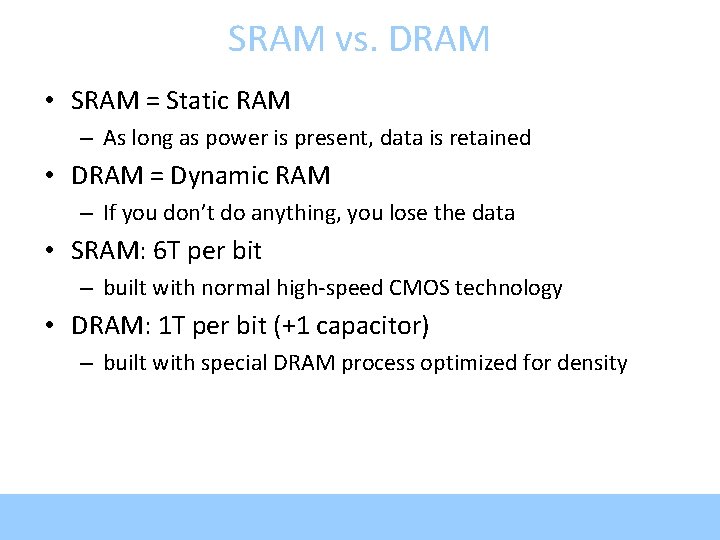
SRAM vs. DRAM • SRAM = Static RAM – As long as power is present, data is retained • DRAM = Dynamic RAM – If you don’t do anything, you lose the data • SRAM: 6 T per bit – built with normal high-speed CMOS technology • DRAM: 1 T per bit (+1 capacitor) – built with special DRAM process optimized for density
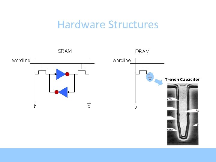
Hardware Structures SRAM DRAM wordline Trench Capacitor b b b
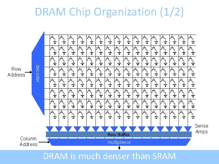
DRAM Chip Organization (1/2) decoder Row Address Column Address Row Buffer multiplexor DRAM is much denser than SRAM Sense Amps
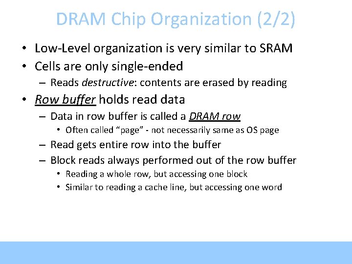
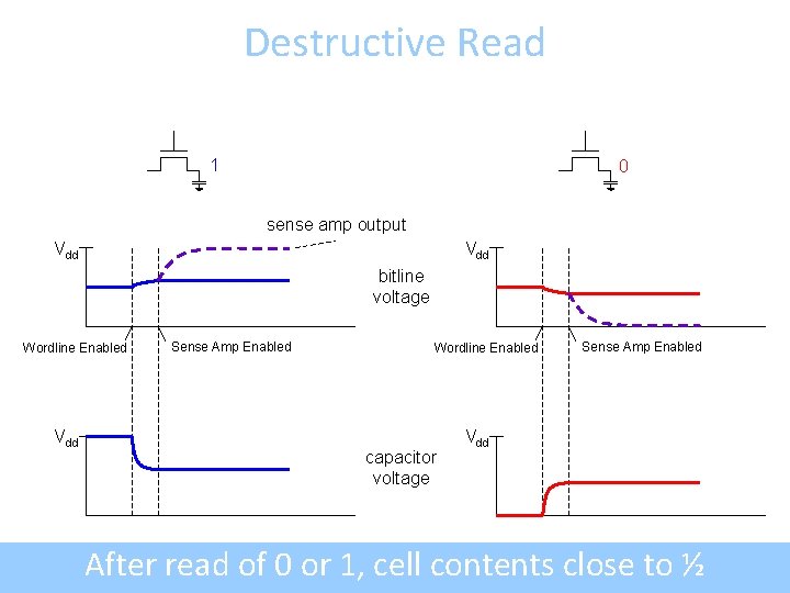
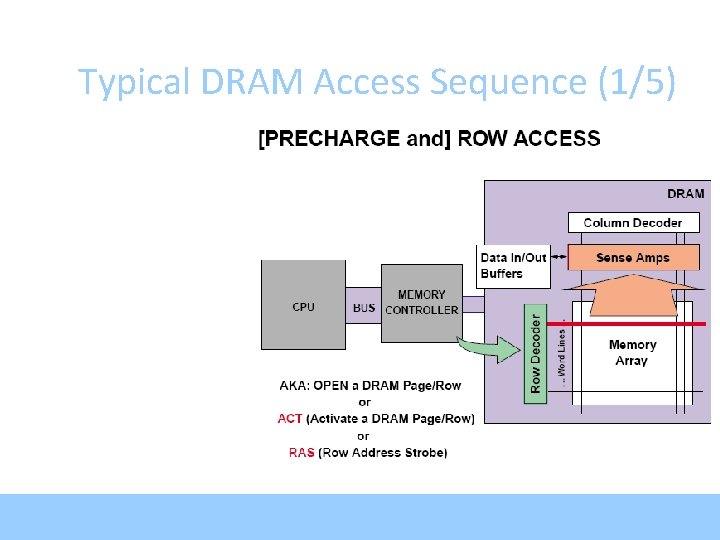
DRAM Chip Organization (2/2) • Low-Level organization is very similar to SRAM • Cells are only single-ended – Reads destructive: contents are erased by reading • Row buffer holds read data – Data in row buffer is called a DRAM row • Often called “page” - not necessarily same as OS page – Read gets entire row into the buffer – Block reads always performed out of the row buffer • Reading a whole row, but accessing one block • Similar to reading a cache line, but accessing one word
Destructive Read 1 0 sense amp output Vdd bitline voltage Wordline Enabled Vdd Sense Amp Enabled Wordline Enabled capacitor voltage Sense Amp Enabled Vdd After read of 0 or 1, cell contents close to ½
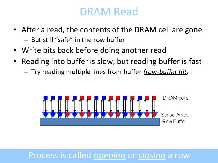
DRAM Read • After a read, the contents of the DRAM cell are gone – But still “safe” in the row buffer • Write bits back before doing another read • Reading into buffer is slow, but reading buffer is fast – Try reading multiple lines from buffer (row-buffer hit) DRAM cells Sense Amps Row Buffer Process is called opening or closing a row
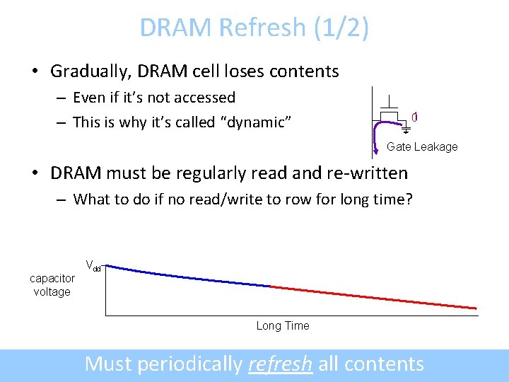
DRAM Refresh (1/2) • Gradually, DRAM cell loses contents – Even if it’s not accessed – This is why it’s called “dynamic” 01 Gate Leakage • DRAM must be regularly read and re-written – What to do if no read/write to row for long time? capacitor voltage Vdd Long Time Must periodically refresh all contents
DRAM Refresh (2/2) • Burst Refresh – Stop the world, refresh all memory • Distributed refresh – Space out refresh one row at a time – Avoids blocking memory for a long time • Self-refresh (low-power mode) – Tell DRAM to refresh itself – Turn off memory controller – Takes some time to exit self-refresh
Typical DRAM Access Sequence (1/5)
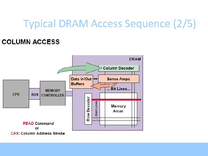
Typical DRAM Access Sequence (2/5)
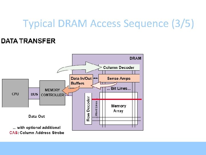
Typical DRAM Access Sequence (3/5)
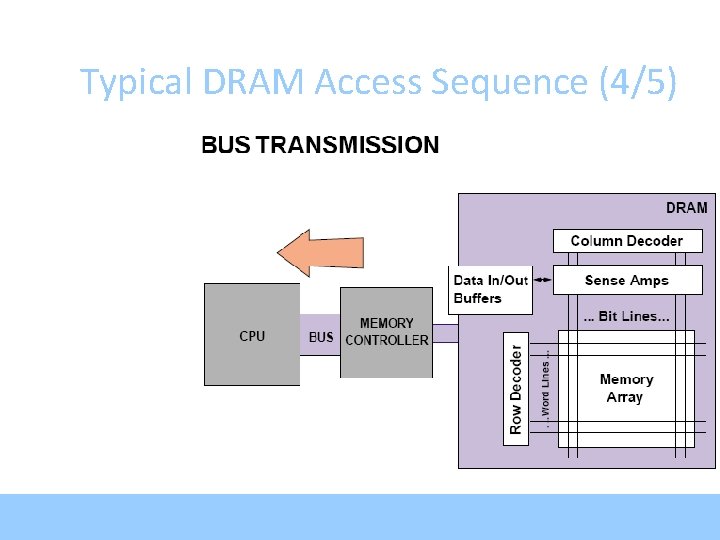
Typical DRAM Access Sequence (4/5)
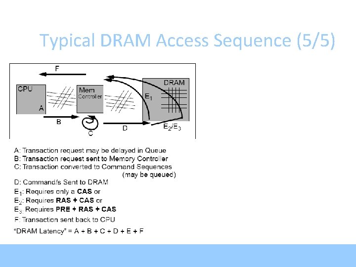
Typical DRAM Access Sequence (5/5)
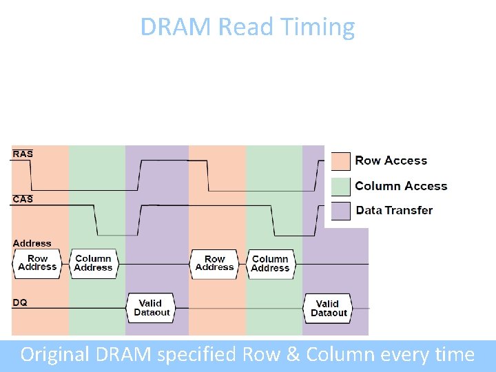
DRAM Read Timing Original DRAM specified Row & Column every time
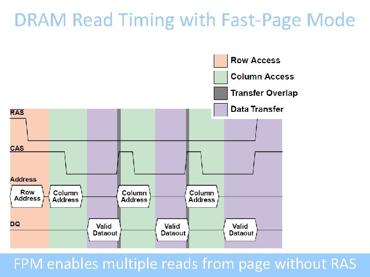
DRAM Read Timing with Fast-Page Mode FPM enables multiple reads from page without RAS
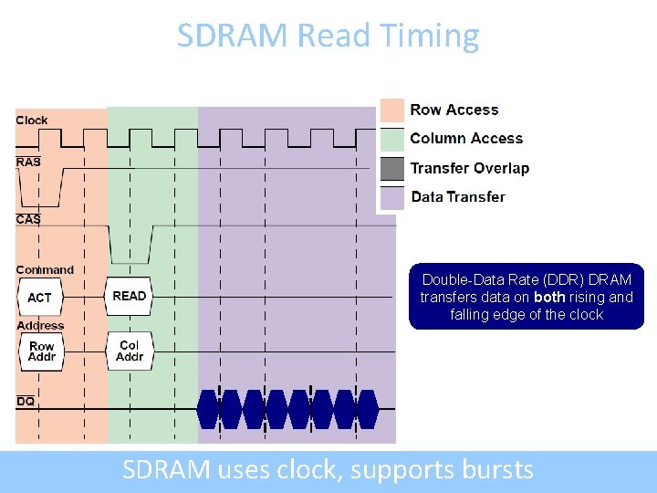
SDRAM Read Timing Double-Data Rate (DDR) DRAM transfers data on both rising and falling edge of the clock SDRAM uses clock, supports bursts
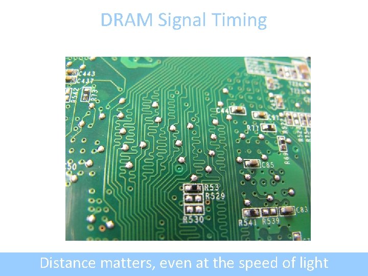
DRAM Signal Timing Distance matters, even at the speed of light
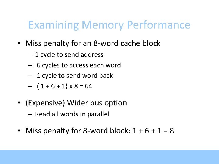
Examining Memory Performance • Miss penalty for an 8 -word cache block – – 1 cycle to send address 6 cycles to access each word 1 cycle to send word back ( 1 + 6 + 1) x 8 = 64 • (Expensive) Wider bus option – Read all words in parallel • Miss penalty for 8 -word block: 1 + 6 + 1 = 8
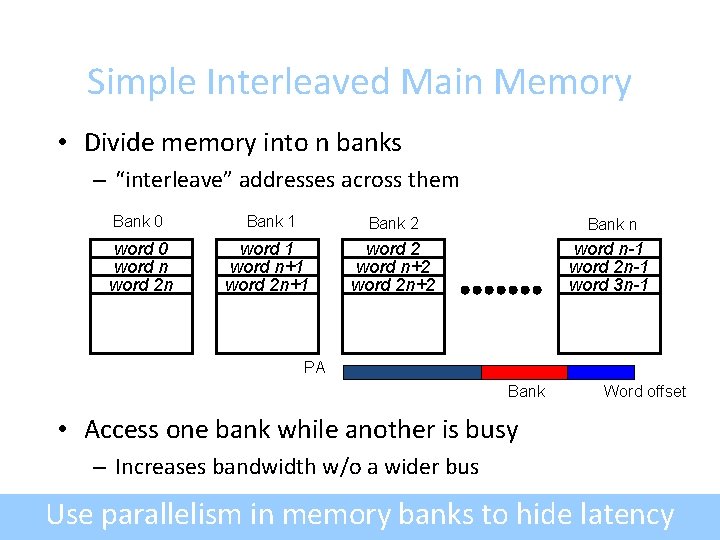
Simple Interleaved Main Memory • Divide memory into n banks – “interleave” addresses across them Bank 0 Bank 1 Bank 2 Bank n word 0 word n word 2 n word 1 word n+1 word 2 word n+2 word 2 n+2 word n-1 word 2 n-1 word 3 n-1 PA Bank Word offset • Access one bank while another is busy – Increases bandwidth w/o a wider bus Use parallelism in memory banks to hide latency
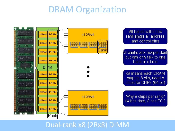
DRAM Organization DRAM DRAM All banks within the rank share all address and control pins x 8 DRAM Bank All banks are independent, but can only talk to one bank at a time DIMM DRAM DRAM x 8 means each DRAM outputs 8 bits, need 8 chips for DDRx (64 -bit) x 8 DRAM DRAM Why 9 chips per rank? 64 bits data, 8 bits ECC Rank Dual-rank x 8 (2 Rx 8) DIMM
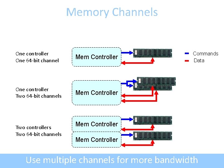
Memory Channels One controller One 64 -bit channel Mem Controller One controller Two 64 -bit channels Mem Controller Two controllers Two 64 -bit channels Commands Data Mem Controller Use multiple channels for more bandwidth
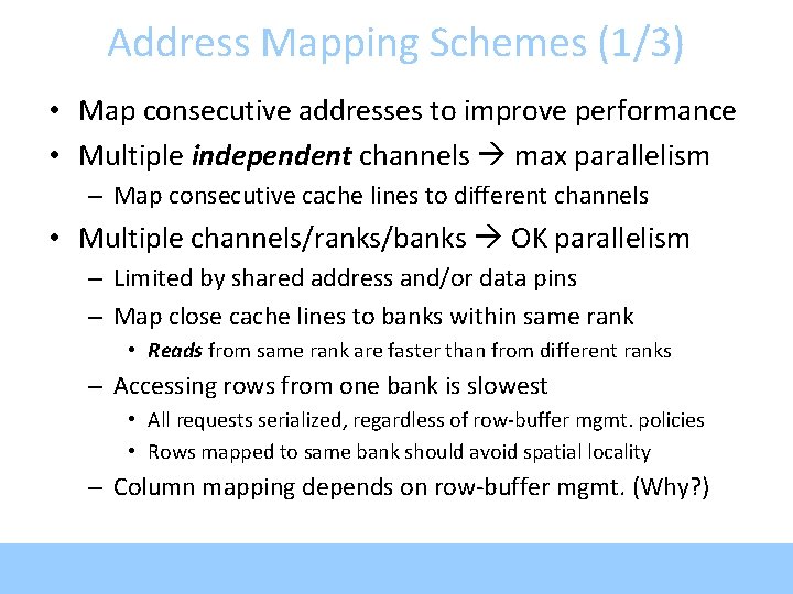
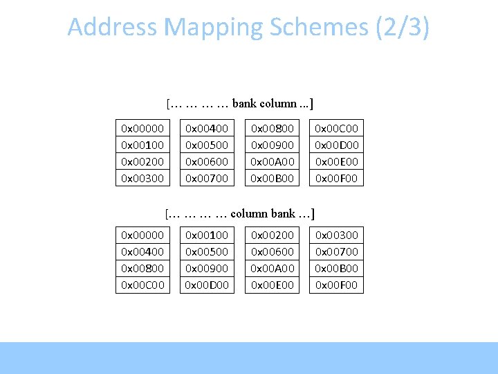
Address Mapping Schemes (1/3) • Map consecutive addresses to improve performance • Multiple independent channels max parallelism – Map consecutive cache lines to different channels • Multiple channels/ranks/banks OK parallelism – Limited by shared address and/or data pins – Map close cache lines to banks within same rank • Reads from same rank are faster than from different ranks – Accessing rows from one bank is slowest • All requests serialized, regardless of row-buffer mgmt. policies • Rows mapped to same bank should avoid spatial locality – Column mapping depends on row-buffer mgmt. (Why? )
Address Mapping Schemes (2/3) [… … bank column. . . ] 0 x 00000 0 x 00100 0 x 00200 0 x 00300 0 x 00400 0 x 00500 0 x 00600 0 x 00700 0 x 00800 0 x 00900 0 x 00 A 00 0 x 00 B 00 0 x 00 C 00 0 x 00 D 00 0 x 00 E 00 0 x 00 F 00 [… … column bank …] 0 x 00000 0 x 00400 0 x 00800 0 x 00 C 00 0 x 00100 0 x 00500 0 x 00900 0 x 00 D 00 0 x 00200 0 x 00600 0 x 00 A 00 0 x 00 E 00 0 x 00300 0 x 00700 0 x 00 B 00 0 x 00 F 00
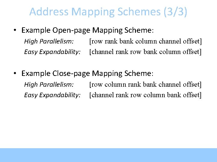
Address Mapping Schemes (3/3) • Example Open-page Mapping Scheme: High Parallelism: Easy Expandability: [row rank bank column channel offset] [channel rank row bank column offset] • Example Close-page Mapping Scheme: High Parallelism: Easy Expandability: [row column rank bank channel offset] [channel rank row column bank offset]
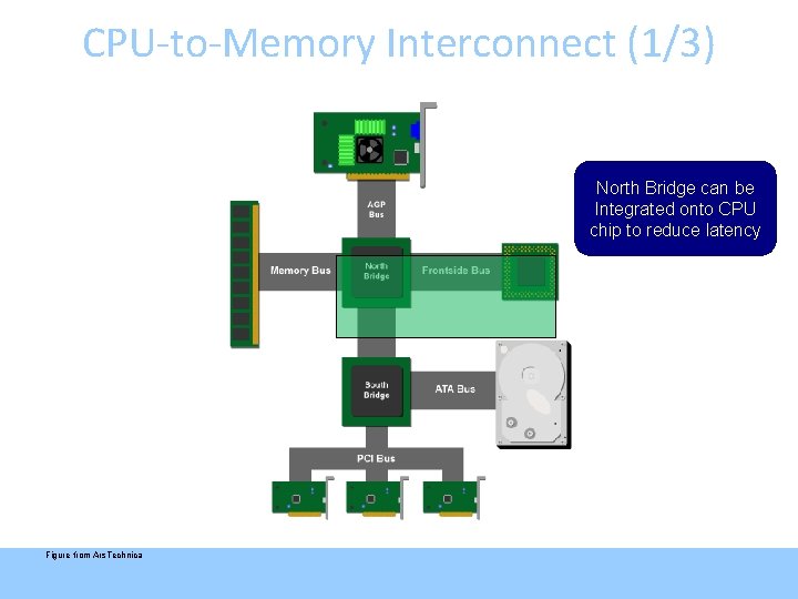
CPU-to-Memory Interconnect (1/3) North Bridge can be Integrated onto CPU chip to reduce latency Figure from Ars. Technica
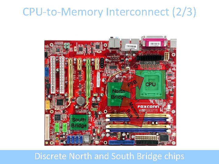
CPU-to-Memory Interconnect (2/3) B FS CPU North Bridge ry mo Me us B South Bridge Discrete North and South Bridge chips
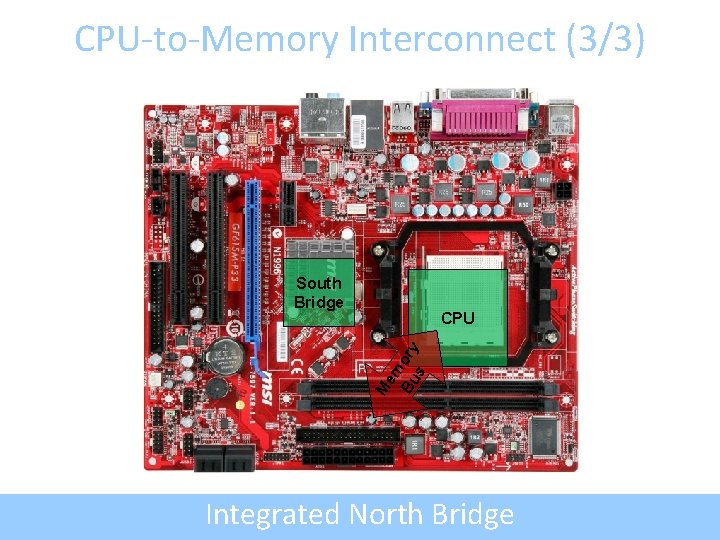
CPU-to-Memory Interconnect (3/3) South Bridge Me m Bu ory s CPU Integrated North Bridge
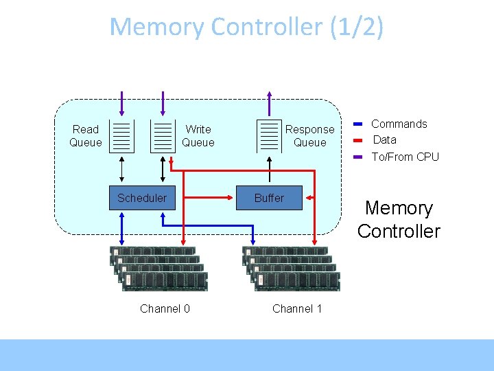
Memory Controller (1/2) Read Queue Write Queue Response Queue Commands Data To/From CPU Scheduler Channel 0 Buffer Channel 1 Memory Controller
Memory Controller (2/2) • Memory controller connects CPU and DRAM • Receives requests after cache misses in LLC – Possibly originating from multiple cores • Complicated piece of hardware, handles: – – DRAM Refresh Row-Buffer Management Policies Address Mapping Schemes Request Scheduling
Row-Buffer Management Policies • Open-page – After access, keep page in DRAM row buffer – Next access to same page lower latency – If access to different page, must close old one first • Good if lots of locality • Close-page – After access, immediately close page in DRAM row buffer – Next access to different page lower latency – If access to different page, old one already closed • Good if no locality (random access)
Request Scheduling (1/3) • Write buffering – Writes can wait until reads are done • Queue DRAM commands – Usually into per-bank queues – Allows easily reordering ops. meant for same bank • Common policies: – First-Come-First-Served (FCFS) – First-Ready—First-Come-First-Served (FR-FCFS)
Request Scheduling (2/3) • First-Come-First-Served – Oldest request first • First-Ready—First-Come-First-Served – – Prioritize column changes over row changes Skip over older conflicting requests Find row hits (on queued reqs. , even if close-page policy) Find oldest • If no conflicts with in-progress request good • Otherwise (if conflicts), try next oldest
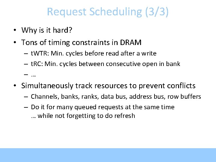
Request Scheduling (3/3) • Why is it hard? • Tons of timing constraints in DRAM – t. WTR: Min. cycles before read after a write – t. RC: Min. cycles between consecutive open in bank –… • Simultaneously track resources to prevent conflicts – Channels, banks, ranks, data bus, address bus, row buffers – Do it for many queued requests at the same time … while not forgetting to do refresh
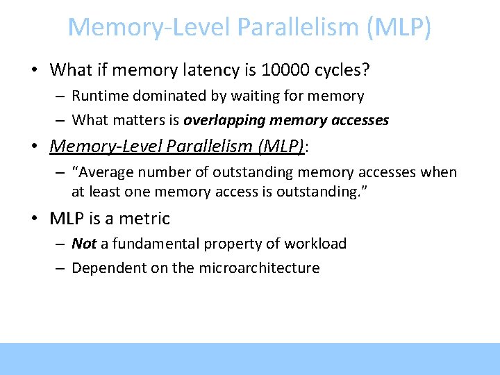
Memory-Level Parallelism (MLP) • What if memory latency is 10000 cycles? – Runtime dominated by waiting for memory – What matters is overlapping memory accesses • Memory-Level Parallelism (MLP): – “Average number of outstanding memory accesses when at least one memory access is outstanding. ” • MLP is a metric – Not a fundamental property of workload – Dependent on the microarchitecture
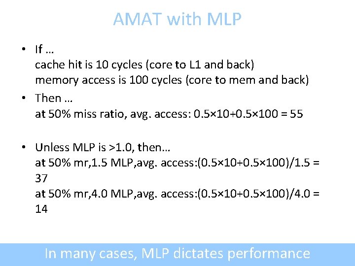
AMAT with MLP • If … cache hit is 10 cycles (core to L 1 and back) memory access is 100 cycles (core to mem and back) • Then … at 50% miss ratio, avg. access: 0. 5× 10+0. 5× 100 = 55 • Unless MLP is >1. 0, then… at 50% mr, 1. 5 MLP, avg. access: (0. 5× 10+0. 5× 100)/1. 5 = 37 at 50% mr, 4. 0 MLP, avg. access: (0. 5× 10+0. 5× 100)/4. 0 = 14 In many cases, MLP dictates performance
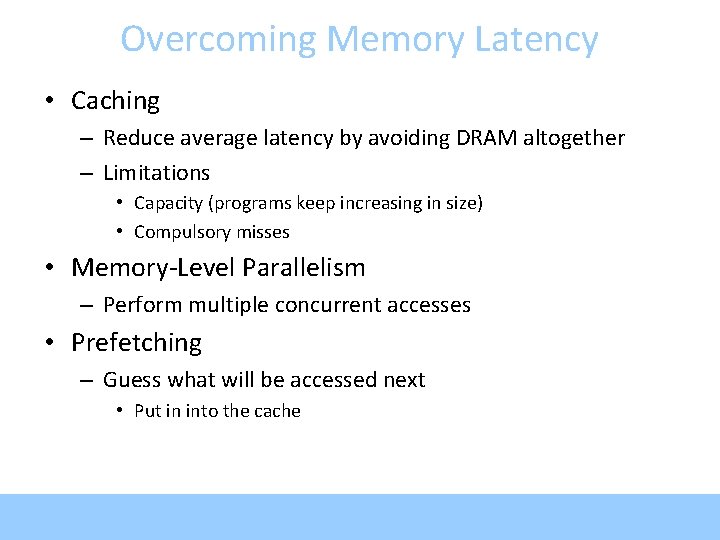
Overcoming Memory Latency • Caching – Reduce average latency by avoiding DRAM altogether – Limitations • Capacity (programs keep increasing in size) • Compulsory misses • Memory-Level Parallelism – Perform multiple concurrent accesses • Prefetching – Guess what will be accessed next • Put in into the cache