Communication system Source Channel Line encoding Modulation Channel


 n n two different voltages for 0 and 1 bits")


 n n If an octet of")
 n replaces strings of four zeros with sequences containing")


")

 for a")
")


")


")


- Slides: 61
Communication system Source Channel Line encoding Modulation Channel Receiver Source Channel Line decoding Demodulation
Digital Data, Digital Signal n Digital signal n n n discrete, discontinuous voltage pulses each pulse is a signal element binary data encoded into signal elements
Comparison of line coding Schemes n n n No DC component signal spectrum clocking error detection signal interference and noise immunity cost and complexity
Encoding Schemes
Nonreturn to Zero-Level (NRZ-L) n n two different voltages for 0 and 1 bits voltage constant during bit interval n no transition I. e. no return to zero voltage such as absence of voltage for zero, constant positive voltage for one more often, negative voltage for one value and positive for the other
Nonreturn to Zero Inverted n nonreturn to zero inverted on ones constant voltage pulse for duration of bit data encoded as presence or absence of signal transition at beginning of bit time n n n transition (low to high or high to low) denotes binary 1 no transition denotes binary 0 example of differential encoding since have n n n data represented by changes rather than levels more reliable detection of transition rather than level easy to lose sense of polarity
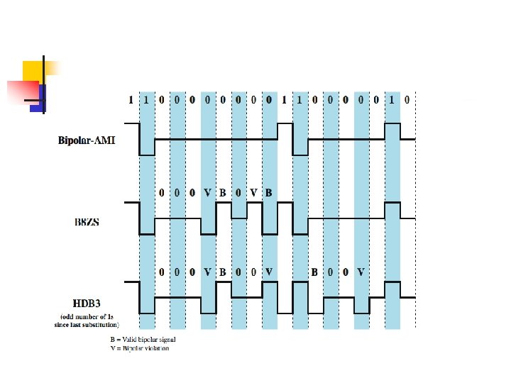
Multilevel Binary Bipolar-AMI n n Use more than two levels Bipolar-AMI n n n n zero represented by no line signal one represented by positive or negative pulse one pulses alternate in polarity no loss of sync if a long string of ones long runs of zeros still a problem no net dc component lower bandwidth easy error detection
Multilevel Binary Pseudoternary n n one represented by absence of line signal zero represented by alternating positive and negative no advantage or disadvantage over bipolar-AMI each used in some applications
Manchester Encoding n n n has transition in middle of each bit period transition serves as clock and data low to high represents one high to low represents zero used by IEEE 802.
Differential Manchester Encoding n n n midbit transition is clocking only transition at start of bit period representing 0 no transition at start of bit period representing 1 n n this is a differential encoding scheme used by IEEE 802. 5
Scrambling n n use scrambling to replace sequences that would produce constant voltage these filling sequences must n n produce enough transitions to sync be recognized by receiver & replaced with original be same length as original design goals n n have no dc component have no long sequences of zero level line signal have no reduction in data rate give error detection capability
bipolar with 8 -zeros substitution (B 8 ZS) n n If an octet of all zeros occurs and the last voltage pulse preceding this octet was positive, then the eight zeros of the octet are encoded as 000+– 0–+ If an octet of all zeros occurs and the last voltage pulse preceding this octet was negative, then the eight zeros of the octet are encoded as 000–+0+–
high-density bipolar-3 zeros (HDB 3) n replaces strings of four zeros with sequences containing one or two pulses If the number of marks is odd number, the format should be OOOV n If the number of marks is even number, the format should be BOOV n
Power spectrum of Unipolar binary RZ signal Bipolar signal
Communication system Source Channel Line encoding Modulation Channel Receiver Source Channel Line decoding Demodulation
Data transmission n Communication modes n n n Simplex Half-Duplex or Full-duplex
Transmission modes Asynchronous transmission n n Feature : unnecessary to perfectly synchronized Encoding Technique Used : NRZ Components : Start Bit (1 : transition from 1 to 0), Data (5 -8), stop bit(1, 1. 5, 2 : binary 1) Merit : Easy-to-build Demerit : High overhead e. g. start, stop bit 1 bit, data 8 bit -> overhead = 2/10 = 20 %
Transmission modes Synchronous Transmission n n n Feature : synchronized by sending timing information via separate clock line or embedding in data signal Line coding: Manchester, AMI Component : preamble (8 -bit flag), Control, Data, Control, postamble (8 -bit flag) Merit : Low overhead comparing to Asynchronous transmission. Example : preamble + control + postamble 48 bits data 1000 bits -> overhead = 48/1048 = 4. 6 % data 8000 bits -> overhead = 48/8048 = 0. 6 %
Transmission media n n n Transmission medium is the physical path between transmitter and receiver in a data transmission system. Guided vs unguided (wireless transmission) Characteristics and quality of data communication depend on characteristics of both media and signal. Key concern in design is data rate and distance.
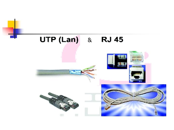
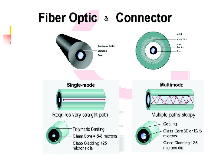
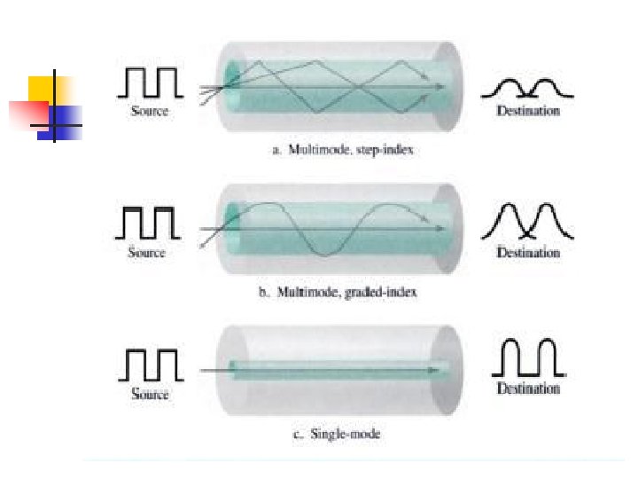
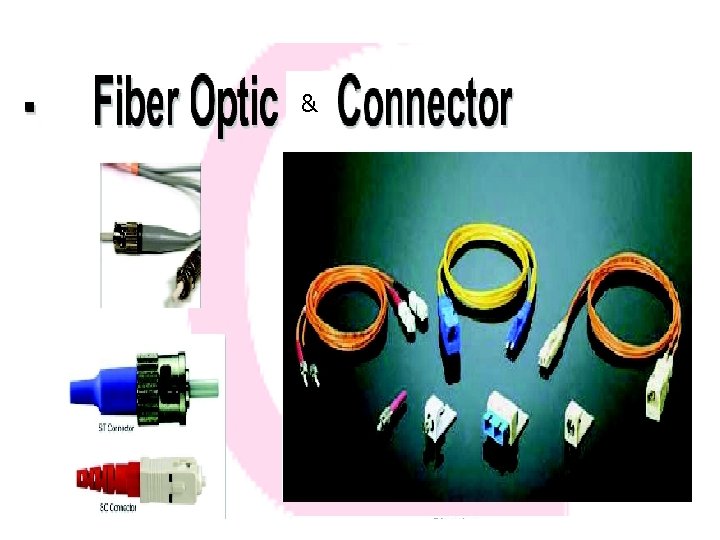
Guided Transmission media n n Two-wire open Twisted pair Coaxial cable Fiber optic
Twisted pair
Coaxial cable & connectors
Guided transmission media Data rate Distance Typical use Two-wire open 19. 2 kbps 50 m Telephone Twisted pair Category 1 -2 <2 Mbps 2 -3 miles Telephone Twisted pair Category 3 -6 200 Mbps 100 m LANs Coaxial cable, Thin 10 Mbps Baseband Single Ch. 100 m LANs Coaxial cable, Thick 10 Mbps Broadband Multi Ch. 2 -3 miles LANs, Cable TV Fiber optic 100 miles Data, video, LANs, WANs 10 Gbps
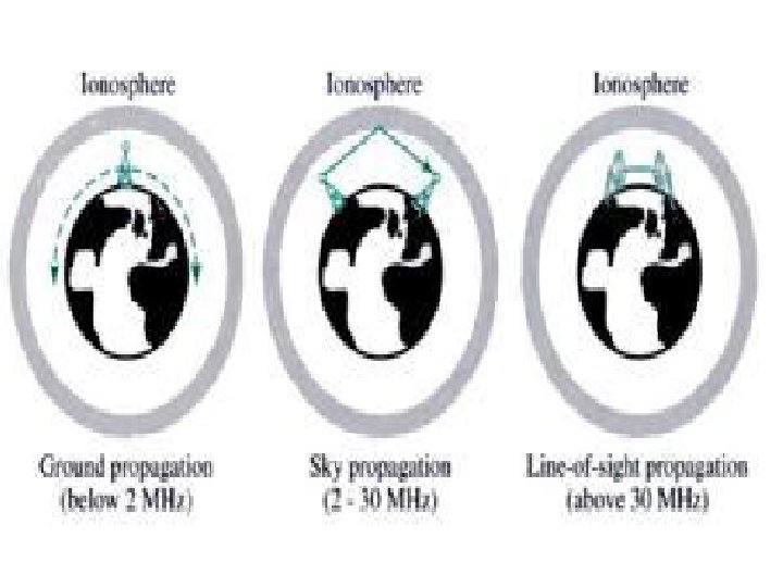
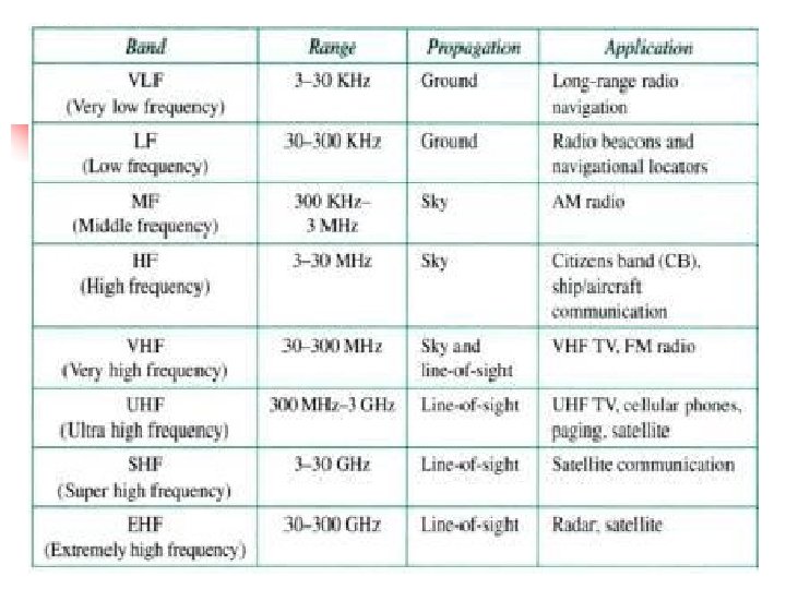
Unguided transmission media Transport electromagnetic waves without using a physical conductor
Geostationary satellites n n The satellite must move at the same speed as the earth so that it seems to be fixed above a certain spot. Orbital speed is based on distance from the planet. This orbit occurs at the equatorial plane and is approximately 22, 000 miles from the surface of the earth. At least 3 Satellite to cover all areas.
Satellite frequency bands Band C Downlink Sat. to earth 3. 7 -4. 2 GHz Uplink Earth to Sat. 5. 925 -6. 425 GHz Ku 11. 7 -12. 2 GHz 14 -14. 5 GHz Ka 17. 7 -21 GHz 27. 5 -31 GHz
Unguided transmission media Data rate Distance Typical use Microwave n-Gbps 20 -30 miles Building to building Satellite n-Gbps Worldwide Long distance Infrared 16 Mbps 1. 5 Miles Short distance
Modulations Amplitude Shift Keying ASK (OOK)
BW for ASK Nbaud is baud rate
n Ex. Given a BW of 10, 000 Hz (1, 00011, 000) for a full-duplex ASK. Find the carriers and the BW in each direction. Assume there is no gap between the bands in two directions. What is the maximum baud rate and bit rate?
Frequency Shift Keying (FSK)
BW for FSK
n EXample: Find the maximum bit rates for an FSK signal if the bandwidth of the medium is 12, 000 Hz, and the difference between the two carriers must be at least 2000 Hz. Transmission is in full-duplex mode.
Phase Shift Keying (PSK)
PSK Constellation diagram
4 -PSK
4 -PSK Constellation diagram
8 -PSK
BW for PSK n n The same as ASK Ex. Given a bandwidth of 5000 Hz for an 8 -PSK signal, what are the baud rate and bit rate?
n PSK is not susceptible to the noise degradation that affects ASK, nor the BW limitations of FSK.
Quadrature amplitude modulation (QAM)
BW for QAM n The same as ASK and PSK.
Multiplexing n n n multiple links on 1 physical line common on long-haul, high capacity, links have FDM and TDM alternatives
Frequency Division Multiplexing
FDM System Overview
FDM Voiceband Example
Wavelength Division Multiplexing n n FDM with multiple beams of light at different freq carried over optical fiber links
Synchronous Time Division Multiplexing
TDM System Overview
Communication system Source Channel Line encoding Modulation Channel Receiver Source Channel Line decoding Demodulation
Distortion n n Amplitude distortion Phase distortion
Amplitude response of a telephone channel n Insertion loss=10 log 10 P 0/P 2 P 2=Power delivered to a load by the channel P 0=Power delivered to the same load without channel
Envelope delay and Phase response of a telephone channel n Envelope delay is the derivative of the phase shift
Tx A Channel B Equalizer C Threshold Detector D E Retiming Circuit Clock Extraction F Tx Rx Equalizer Threshold detector Data Clock (Trig ������ )