Communication in Power System Introduction Central control and


 • Most operations in DNs lacks remote controls")


 1. 2. 3. 4. Data Engineering populates the")


 alert 2) fault location 3) supply restoration Trouble Calls Fault SCADA alarms 1")


- Slides: 29
Communication in Power System
Introduction • Central control and management is regarded as the nerve of any power network – Coordination of all operation strategies • The study discusses: – Elements of upper 3 control layers as they influence control and automation of distribution networks – It introduces areas where system design is crucial
Power system control • Why power system control? – Change in business process and environments compound the complexity of the network • Privatization, deregulation – consumers’ free choice of companies • Increase in public awareness - quantifying cost and quality of power • Better performance of core business functions – How can utilities meet this increase in complexity ? • Real-time and IT systems • Right sizing of their operation activities
Power System Operation • It requires the balanced to be maintain between security, economy and quality while delivering Energy from the source to the consumption points. • Power balance includes: – Types & size of generator, Network structure & condition, Demand characteristics of end user. – New business environment includes the following to power balance • Balancing the rules of regulation and a free market • SCADA systems have simplified operation functions for operators • Increased level of automation in decision making
Operation functions Operation Actions Instantaneous operation Real-time monitoring of system demand loads, power generation, network power flow, voltage level control Operation planning Short (a few hours) and Long (a few months) planning, i. e load forecasting Operation reporting Keeps statistics on performance, disturbance, loading as input into planning & accounting functions
Operations Environment of Distributions Networks (DNs) • Most operations in DNs lacks remote controls & real-time monitoring – Not more than 10% of switches are SCADA operated – DNs require manual intervention for decision making and restoration • Responsibilities of control personnel – Normal conditions operation: meeting unplanned situation – Emergency condition operation: restoring network as quick as possible – Administration : daily tasks of logging events, report, asset management • In DMS, the support systems outside SCADA – Operating diagram and geographical maps of network and devices – Repair truck inventory of network spares – Trouble calls from customer to identify trouble location of faults – Mobile communication and data interaction between control centre and field
Evolution of Distribution Management Systems
Typical DMS Evolution Paths Integrated DMSs ? – to share data models & interface different data sources to form integrated source that serve the need of the operator The evolution of started from different paths Current DMSs have now converged to a common functionality
A Full DMS • • Horizontal- provides corporate asset data to support a full DMS Vertical- gives the domain of operation’s organization of the utility
Basic DMS Functions (for Modern DMS) 1. 2. 3. 4. Data Engineering populates the required data into the DMS CROM (umbrella function) – Control room graphics – Interface to SCADA – Switching job SCADA – Monitoring and control of Distr. Sys in real-time Advanced Application – Real-time evaluation and study of loading & load flow before switching sequence Outage Management – Process of making a customer's call – Diagnosing the fault location – Crew management – Job management – Report and statistics
Operation of real-time and manual controlled portion of the Network of a full DMS – SCADA – Crew and job management – Switching scheduling and planning – Operating diagram maintenance and dressing (note and tagging) – Economic deployment of network resources – Temporary and permanent change to the network – Introduction of new asset and plant on the network – Data sources outside the control room such as GIS, trouble calls and soon. – Asset management systems – Common data engineering for all portion and components of the network within the DMS – Timely synchronisation of asoperated and as-built network facility databases
Basic of a REAL-TIME Control System SCADA Supervisory Control And Data Acquisition Uses: • monitoring and controlling SCADA System consists of: Ø Human-Machine interface Ø supervisory (computer) system (SS) Ø Remote Terminal Units (RTUs) Ø Programmable Logic Controller (PLCs) Ø Communication connects SS & RTU
Control System SCADA
Functions of SCADA: Data acquisition Monitoring and event processing Control Scada Central Control Units Application-specific decisions support Data storage archieving and analysis Reporting
Functions of Scada Monitoring and event processing Data acquisition Status inductions Measured values Energy values Status monitoring Limits values monitoring
Limit values Upper metering limit Upper alarm zone Lower alarm zone Zone for normal operation Lower warning limit Lower alarm limit Lower warning zone Lower alarm zone Lower metering limit Zero value Outside zero-zone Upper Warning limit
Postmortem review Individual device control Control Messages to Regulating equip, ment Control functions Automatic control Sequential control Data storage archieving and analysis Server
Outage Management Involves three discrete phases: • Outage alert • Fault location • Fault isolation and supply restoration
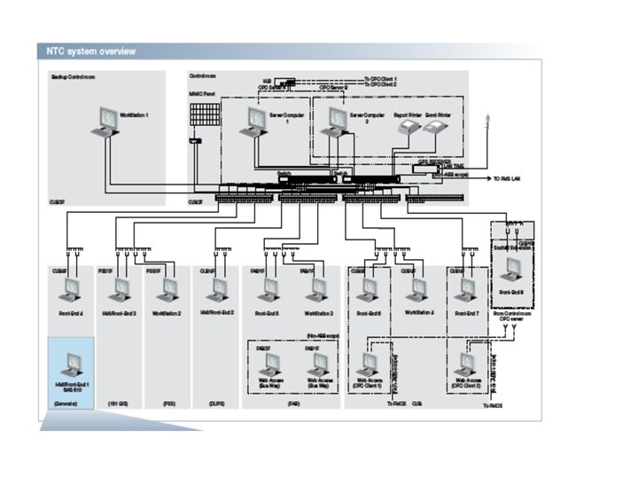
A modern overall concept for the control and monitoring of the six substations
1) alert 2) fault location 3) supply restoration Trouble Calls Fault SCADA alarms 1 Substation feeders • Operation/protection circuit breaker Automated feeder switching devices • Fault passage indicator (FPI) Occurs 1 Network connectivity model Portable state (2) ØEstimation of faults ØFault location ØRepair plans Verified state (2) Confirmation of: ØFault location ØOutage extent ØSwitching plan ØRestoration plan 1 • Loss of supply • Observation of damage Switching plan execution (3) ØFault isolation ØPartial supply restoration ØRepairs ØFinal restoration Outage engine 1 Monitoring devices • PMU • Meter-initiated report
Trouble Call-Based Advanced Application. Based Outage Management Designed to extract maximum information: Triggered by real time information from Scada which in turn: (FLIR) • to determine fault location • to provide up to date • Fault localisation (FL) information on outage • progress restoration monitoring • Fault isolation (I) • and finally to maintain statistics • Service restoration (SR) Two approaches to trouble call outage management system Ø GIS-Centric Ø SCADA-Centric
Decision Support Tools • • 1. 2. 3. Real-time environment Triggered: Manually – on operator demand Cyclically Event driven – network configuration change • • • Operation load flow Fault Calculation Loss Minimization VAR Control Volt Control Data Dependency
Operator Load flow Steady-state solution of power network 2 1 ØStatic load calibration e. g. load profiles, number of supplied customers and Seasons. ØStatic results of active and real power. topology load calibration Uses: Østatic results of power consumption, Ølatest measurement values Øand current topology of network üDetermine dynamic values of active and reactive power consumption 3 final step: Ø Adjuncts non-measured values and missing values ØTo represent state of network loading with losses included
Loss Minimization Fault Calculation Two categories: Ø Balanced and symmetrical Ø Three phase faults and asymmetric faults Investigate reduction of radial distribution network Ø Ø Identify switching changes Reduce distributions loses Verify operating limits Restrict optimazition to reuse remotely controlled switches
VAR Control MV capacitor banks at HV/MV Substations and MV feeders Step 1: Determine service area operating state Ø Normal state Ø VAR compensation Ø Over-VAR compensation state Use when demand exceeds supply Or restrict power Ø Target Voltage Reduction Ø Target Load Reduction
Subsystems Substation Automation Substation Local Automation Scada as the main system • Involves: Ø Ø Ø RTU-Based Designs Proprietary Designs UNIX/PLC Designs PC/PLC Designs Black Box Design Most common architecture used today • Local system sends: • Control commands • Device setting and parameter data • Time synchronization messages Functions include: Ø Relay settings Ø Automatic load disconnection and reconnection Ø Event reporting and control Ø Substation level and feeder level conection Ø etc
Hybrid Network Architecture for Substation Automation Applications
Thank You