Commissioning and Performance of the CMS Silicon Pixel


- Slides: 24

Commissioning and Performance of the CMS Silicon Pixel Tracker Detector Gavril Giurgiu, Johns Hopkins University on behalf of CMS collaboration RD 09 30 September - 2 October 2009, Florence, Italy G. Giurgiu, CMS Pixel Detector, RD 09

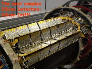
CMS and LHC - LHC plan to start at the end of 2009 - beam energy of 450 Ge. V – 5 Te. V - integrate 200 pb-1 in first one year run - CMS – general purpose detector with precision silicon tracker: - inner silicon pixel detector - silicon strip detector G. Giurgiu, CMS Pixel Detector, RD 09 2

CMS Pixel Detector - CMS pixel detector provides precise tracking close to interaction point - Important for identification of long lived B hadron decays (b tagging) - B tagging crucial in many measurements from top quark to Higgs and searches for exotic physics - Two components: - barrel (BPIX) - forward or endcap (FPIX) G. Giurgiu, CMS Pixel Detector, RD 09 3

CMS Pixel Detector - Barrel Pixel Detector (BPIX): - 3 layers at radii of 4. 3, 7. 2 and 11. 0 cm - 11520 Read Out Chips (ROCs) with 52 × 80 = 4160 pixels per ROC → 48 M pixels - Forward Pixel Detector (FPIX): - 2 disks on each side at 34. 5 and 46. 5 cm from IP - blades 20° tilted to enhance charge sharing - 4320 ROCs → 18 M pixels - Pixel size : 100 mm × 150 mm - Automatic zero-suppression - Each sensor pixel bump bonded to ROC - Each pixel has an adjustable threshold G. Giurgiu, CMS Pixel Detector, RD 09 4

Pixel Detector Status - Most of pixel detector is operational. Very few faulty components: only 0. 9% (108 out of 11520) barrel ROCs and only 3. 1% (135 out of 4320) endcap ROCs are not operational - Overall 239 out of 15840 (1. 5%) ROCs have problems - Number or dead pixels on working ROCs ~ 0. 01% - Very few noisy pixels (rate > 0. 001): - few of hundreds out of 66 M pixels → ~0. 0005% ! - Noisy pixels monitored by Data Quality Monitoring System and masked in DAQ chain G. Giurgiu, CMS Pixel Detector, RD 09 5

Pixel Thresholds - Pixel threshold is the charge above which the pixel is read out - pixel thresholds impact pixel hit resolution - Noise is 100 -200 electrons - small compared to 22000 edeposited by MIP in ~280 mm silicon layer Efficiency - Thresholds measured using “S-curve” scan: efficiency vs injected charge - injected charge controlled by “VCAL” parameter - on average, injected charge (in electrons) = VCAL × 65. 5 – 414 electrons - above parameters determined from x-ray tests suffer from large pixel to pixel variations (± 8. 9, ± 574) noise 50% efficiency - VCAL variations degrade pixel hit resolution by up to 20% in certain cases - plan to calibrate VCAL with collision tracks and gain up to 20% in hit resolution G. Giurgiu, CMS Pixel Detector, RD 09 Atypical 2008 example - high threshold - high noise threshold 6 Charge (≈65 electrons/unit)

Pixel Thresholds from 2008 to 2009 - Thresholds greatly improved (lowered) between 08 and 09 cosmic data taking - Minimized for each ROC - In barrel (BPix) about 33% of ROCs are set at higher thresholds (can be improved) - Barrel: mean = 2737 e- Forward: mean = 2481 e rms = 223 e- rms = 164 e- G. Giurgiu, CMS Pixel Detector, RD 09 7

ADC to Electron Charge Calibration - Pixel charge is digitized and read out in ADC counts - Transform charge back into electrons using “gain/pedestal” calibration - Inject different known charges (set by VCAL) in determine ADC vs VCAL curve Saturation at ~2 MIPs (~45 ke) Example gain curve - Determine slope (gain) and offset (pedestal) from fit to ADC vs VCAL curve for each pixel VCAL units - Charge in ADC counts = gain × VCAL + pedestal - Charge in electrons = 65. 5 × VCAL – 414 = = 65. 5 × [(measured charge in ADC counts) – pedestal] / gain - 414 G. Giurgiu, CMS Pixel Detector, RD 09 8

Charge Calibration (cont) - Dedicated charge calibration runs determine gain/pedestal for each pixel - Negative pedestals due to not fully optimized ROC parameters - will be corrected before LHC start G. Giurgiu, CMS Pixel Detector, RD 09 9

Commissioning with Cosmic Rays - Barrel and Endcaps installed in July 2008 - Two cosmic ray data taking periods: - October – November 2008 (CRAFT 08) - initial alignment and first measurements of: - hit efficiency - resolution - Lorentz angle… - July – August 2009 (CRAFT 09) - detector moved to recover channels and improve cooling - repeat alignment and measurements - Data taken with magnetic field in both zero and 3. 8 Tesla configuration (CRUZET, CRAFT) - Recorded ~300 M (~200 M) in 08 (09) of cosmic muon tracks with B field on - Only ~3% of all tracks pass through the pixel detector - ~85, 000 tracks in pixel detector in CRAFT 2008 and >65, 000 in CRAFT 2009 - average of 3 pixel hits per track → hundreds of thousand of pixel hits to study from cosmics G. Giurgiu, CMS Pixel Detector, RD 09 10

Commissioning with Cosmic Rays G. Giurgiu, CMS Pixel Detector, RD 09 11

Cosmic Rays through the CMS Tracker Cosmic muon through CMS Cosmic muon through pixel detector G. Giurgiu, CMS Pixel Detector, RD 09 12

Pixel Detector Hit Map from Cosmics G. Giurgiu, CMS Pixel Detector, RD 09 13

Pixel Cluster Charge - Select clusters produced in conditions similar to collision tracks: - incidence angle within to 90° ± 12° - PT > 4 Ge. V - only clusters with at least 2 pixels - Charge corrected to normal incidence - Charge distribution in data agrees well with CMS simulation - Landau peak at ~22 ke as expected from ~280 mm silicon layer threshold ~ 2700 e- - Tracking particle passing through pixel layer deposits charge in few pixels and produces a pixel cluster - Pixel noise (~100 e-) and thresholds (~2700 e-) are much lower than cluster charge G. Giurgiu, CMS Pixel Detector, RD 09 14

Lorentz Angle - Cluster shapes are affected by Lorentz drift of electrons in 3. 8 Tesla magnetic field - Lorentz drift enhances charge sharing between pixels which improves hit resolution E - Important to account for Lorentz drift when reconstructing hit position - Lorentz angle determined using cluster size which is minimum for tracks passing through sensor along Lorentz drift direction: amin = q. Lorentz + 90° Barrel: q. Lorentz ≈ 22° Endcap: q. Lorentz ≈ 5° - Very good agreement between data: cot(amin) = -0. 405± 0. 003 and simulation: cot(amin) = -0. 397± 0. 003 cosmic simulation data G. Giurgiu, CMS Pixel Detector, RD 09 15

Pixel Hit Efficiency - Efficiency defined as number of observed hits divided by total number of expected hits (observed hits and missing hits) - Missing hits are intersections of tracks with pixel layers where no hits are observed - Efficiency ≈ 99% - Known bad modules (no HV, readout problems) are excluded G. Giurgiu, CMS Pixel Detector, RD 09 16

Pixel Hit Resolution - Use tracks passing through two modules in same layer (>30 tracks / overlap) - difference between hit and predicted positions on overlap modules Δxhit = xhit 1 - xhit 2, Δxpred = xpred 1 - xpred 2 - For each overlap site, width of double difference is determined: width 2 - σ(Δxpred)2 = σ(Δxhit)2 X resolution: 19 ± 2 μm Y resolution: 31 ± 3 μm - Measured resolution in agreement with simulation G. Giurgiu, CMS Pixel Detector, RD 09 17

Pixel Alignment (see talk by Jula Draeger for details) - Alignment performed first in 2008 and repeated in 2009 with 2. 3 M tracks - Pixel detector moved between the two alignment procedures - Compare Distribution of Median Residuals (DMR) of all modules using old 08 alignment constants and updated 09 constants - Achieve DMR of 3 -4 mm for barrel and 13 -14 mm for endcaps - Obtain similar results with different alignment algorithms G. Giurgiu, CMS Pixel Detector, RD 09 18

Conclusions - The CMS Pixel detector installed, working well with ~99% of channels operational and very few noisy or dead pixels - Pixel hit efficiency ≈ 99% - Established calibration procedures - Lorentz angle, gain/pedestal, … - Measured pixel hit resolution and found agreement with simulation - Aligned pixel detector to ~4 mm in barrel and ~15 mm in endcaps - Looking forward for taking collision data G. Giurgiu, CMS Pixel Detector, RD 09 19

Backup G. Giurgiu, CMS Pixel Detector, RD 09 20

G. Giurgiu, CMS Pixel Detector, RD 09 21

G. Giurgiu, CMS Pixel Detector, RD 09 22

G. Giurgiu, CMS Pixel Detector, RD 09 23

Read Out Chip (ROC) G. Giurgiu, CMS Pixel Detector, RD 09 24
 Performance pixel
 Integrated commissioning and progress system
 Commissioning cycle
 Aecp prerequisites
 Steps
Steps Ecs commissioning
 Fortis furnace commissioning sheet
 Scientist project
 Commissioning management systems
 Commissioning cycle
 Value based commissioning
 Vacuum systems commissioning
 Power system commissioning
 Central commissioning facility research management system
 Dominik sikora
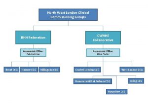
 Brent clinical commissioning group
 Commissioning
 Aabc commissioning group
 Lidl stores with ev charging
 Croydon clinical commissioning group
 Ecs commissioning
 Neighbors of a pixel
 4-neighbors and 8 neighbors of a pixel example
 Diode germanium vs silicon
 Oxygen and silicon
