Columns Review Short Columns Axial load Moment Usually

 Usually moment is represented by axial")


")
 Restrained at both ends b) One hinged end Non-sway")


 divide By 7. 0 and")


: 1. 2 D +1. 6 L Case (2): 1. 2 D +")


- Slides: 47
Columns
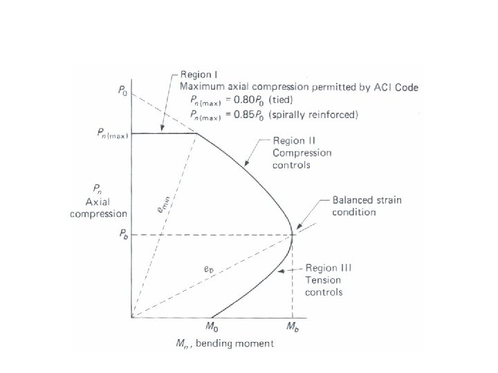
Review Short Columns (Axial load + Moment ) Usually moment is represented by axial load times eccentricity, i. e.
Behavior under Combined Bending and Axial Loads Interaction Diagram Between Axial Load and Moment ( Failure Envelope ) Concrete crushes before steel yields Steel yields before concrete crushes Note: Any combination of P and M outside the envelope will cause
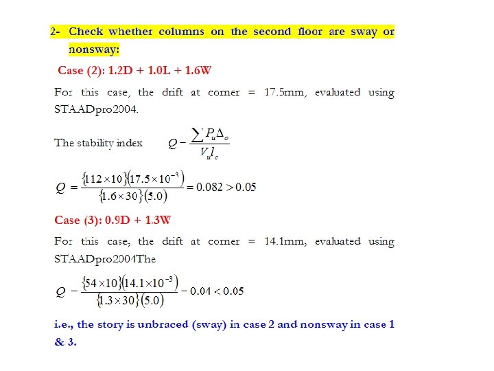
Define Sway & non- sway frame Stability index
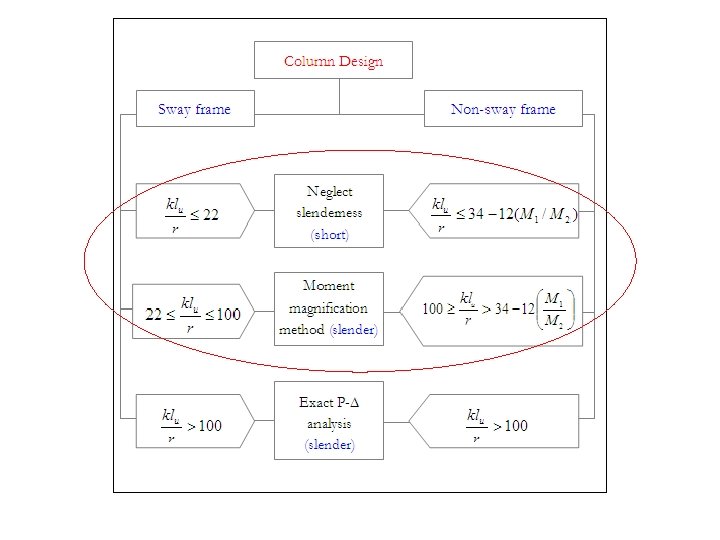
The ACI Procedure for Classifying Short and Slender Column
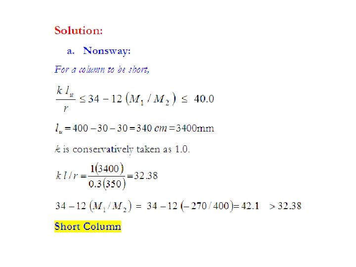
= unsupported length of member, defined in ACI Code 10. 11. 3 as clear distance between floor slabs, beams, or other members capable of providing lateral support, as shown = radius of gyration associated with axis about which bending is occurring. For rectangular cross sections r = 0. 30 h, and for circular sections, r = 0. 25 h as specified by ACI Code 10. 11. 2.
M 1/M 2 = Ratio of moments at two column ends, where M 2 > M 1 (-1 to 1 range) singular curvature double curvature
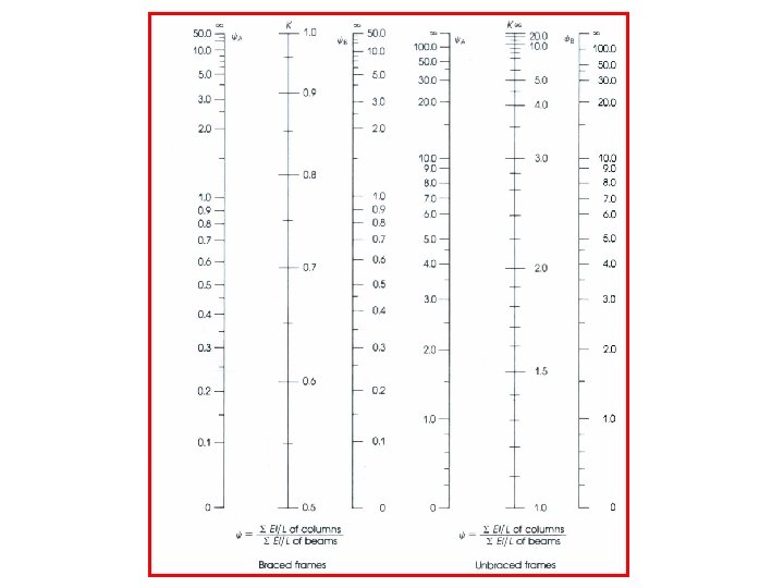
K –Factor = effective length factor
Slenderness Ratio for columns in frames
K –Factor calculatoin For a Braced Frame: (Non-sway)
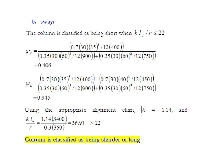
For a Sway Frame: a) Restrained at both ends b) One hinged end Non-sway frames: Sway frames:
Example 1 The frame shown in Figure s consisting of members with rectangular cross sections, made of the same strength concrete. Considering buckling in the plane of the figure, categorize column FE as long or short if the frame is: Nonsway Sway 270 KN. m 400 KN. m
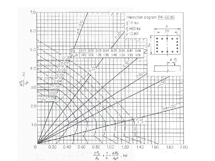
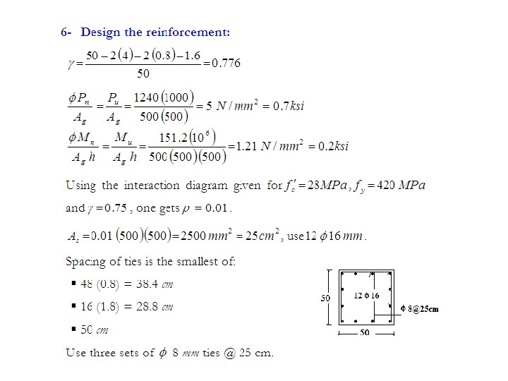
Example 2 Design reinforcement for a 400 mm x 500 mm tied column. The column, which is part of a braced frame, has an unsupported length of 3. 0 m. It is subjected to a factored axial load of 2400 k. N in addition to a factored bending moment as shown. 500 KN. m 250 KN. m
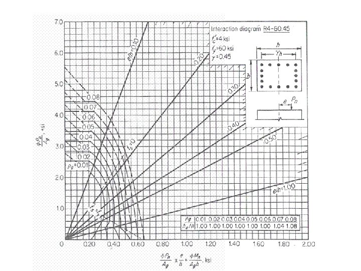
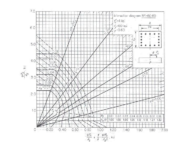
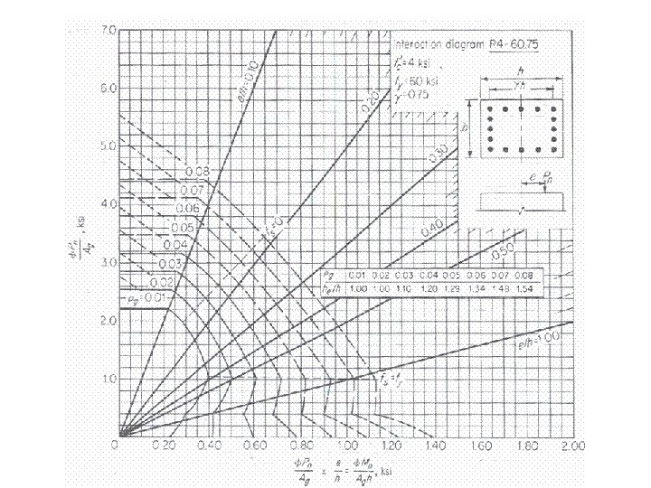
Note to use the last Instruction diagrams (English units) divide By 7. 0 and
Long Columns
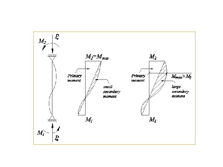
Moment Magnification in Non-sway Frames If the slenderness effects need to be considered. The non-sway magnification factor, dns, will cause an increase in the magnitude of the design moment. where
Moment Magnification in Non-sway Frames The components of the equation for an Euler bucking load for pin-end column and the stiffness, EI is taken as
Moment Magnification in Non-sway Frames A coefficient factor relating the actual moment diagram to the equivalent uniform moment diagram. For members without transverse loads For other conditions, such as members with transverse loads between supports, Cm = 1. 0
Moment Magnification in Non-sway Frames The minimum allowable value of M 2 is In mm The sway frame uses a similar technique, see the text on the components.
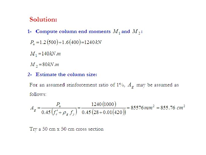
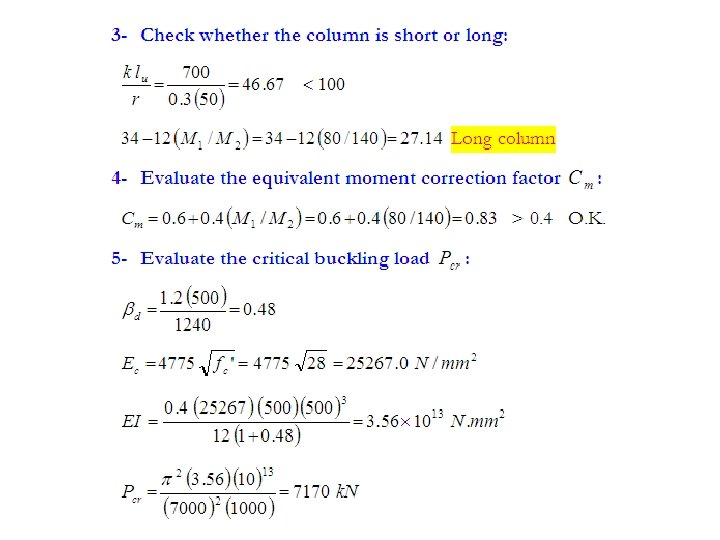
Example 1 Design a 7. 0 m-tall column that carries a service dead load of 500 k. N, and a service live load of 400 k. N, shown in Figure elow 140 KN. m 80 KN. m
Moment Magnification in sway Frames
Example 2
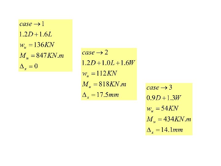
1. 2 D +1. 6 L
1. 2 D +1. 0 L+1. 6 W
0. 9 D +1. 3 W
Lu=500 -30=470 cm Hinged end
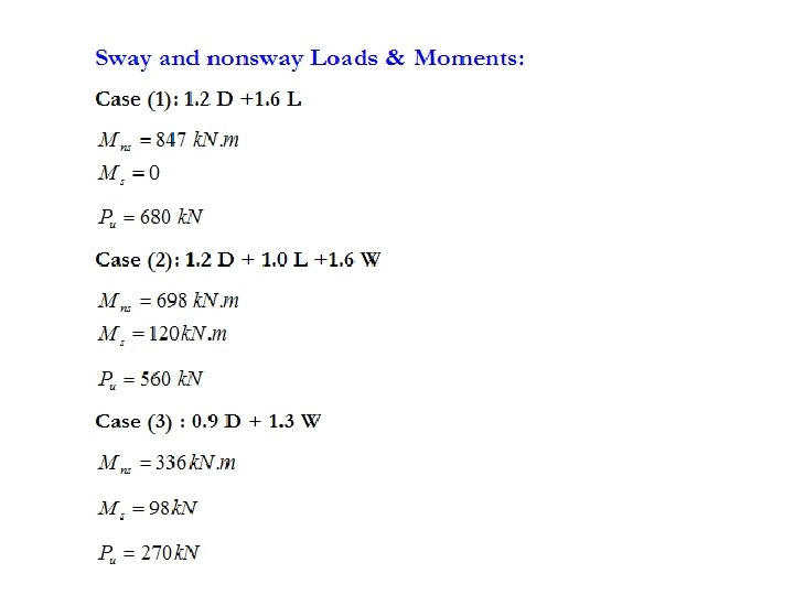
Case (1): 1. 2 D +1. 6 L Case (2): 1. 2 D + 1. 0 L +1. 6 W Case (3) : 0. 9 D + 1. 3 W
Case 1
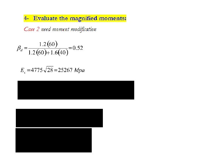
Case 2