
Color Television Receive Multichannel Broadcast Frequency Spectrum Channel

Color Television - Receive Multi-channel Broadcast Frequency Spectrum Channel 1 Channel 2 Channel 3 8 MHz Luminance Tuner Chrominance Sound
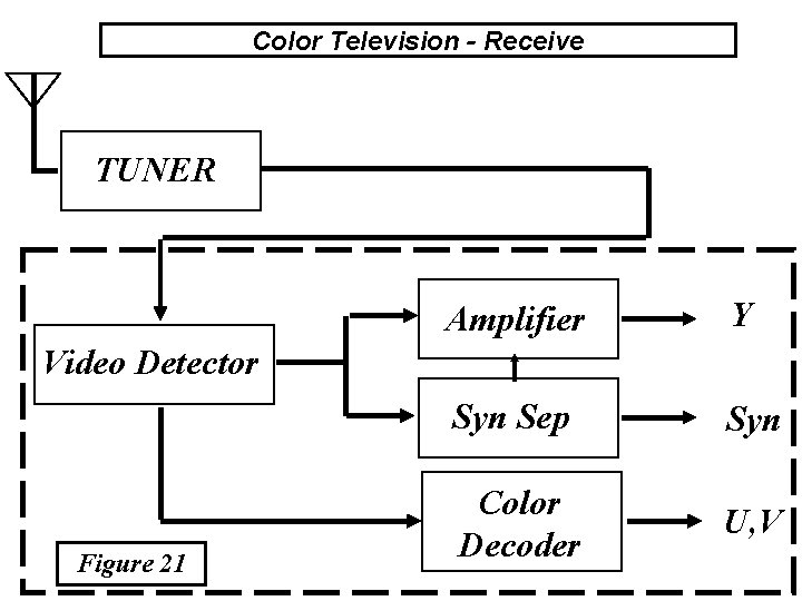
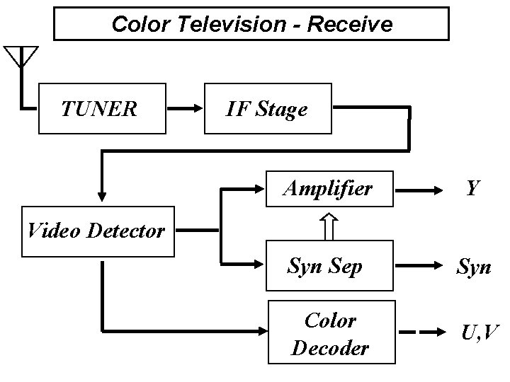
Color Television - Receive TUNER Amplifier Y Syn Sep Syn Color Decoder U, V Video Detector Figure 21
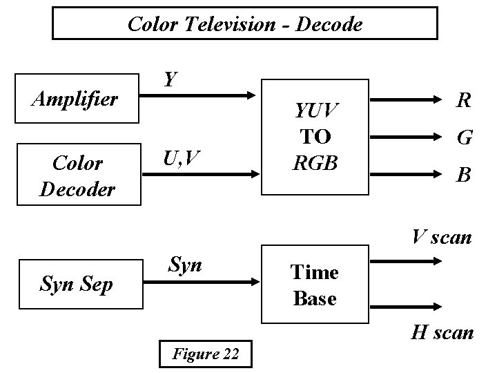
Color Television - Decode Amplifier Color Decoder Y U, V YUV TO RGB R G B V scan Syn Sep Syn Time Base H scan Figure 22
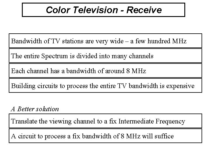
Color Television - Receive Bandwidth of TV stations are very wide – a few hundred MHz The entire Spectrum is divided into many channels Each channel has a bandwidth of around 8 MHz Building circuits to process the entire TV bandwidth is expensive A Better solution Translate the viewing channel to a fix Intermediate Frequency A circuit to process a fix bandwidth of 8 MHz will suffice
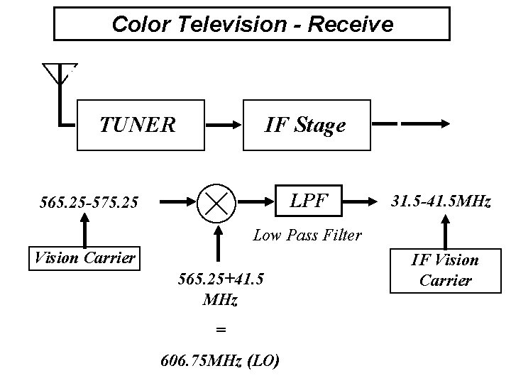
Color Television - Receive TUNER IF Stage LPF 565. 25 -575. 25 31. 5 -41. 5 MHz Low Pass Filter Vision Carrier 565. 25+41. 5 MHz = 606. 75 MHz (LO) IF Vision Carrier
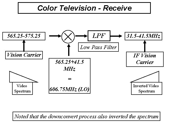
Color Television - Receive LPF 565. 25 -575. 25 31. 5 -41. 5 MHz Low Pass Filter Vision Carrier 565. 25+41. 5 MHz IF Vision Carrier = Video Spectrum 606. 75 MHz (LO) Inverted Video Spectrum Noted that the downconvert process also inverted the spectrum
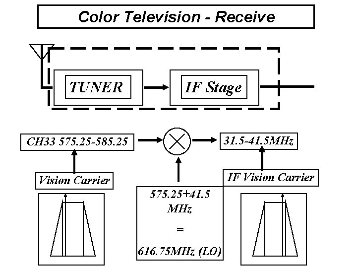
Color Television - Receive TUNER IF Stage 31. 5 -41. 5 MHz CH 33 575. 25 -585. 25 IF Vision Carrier 575. 25+41. 5 MHz = 616. 75 MHz (LO)
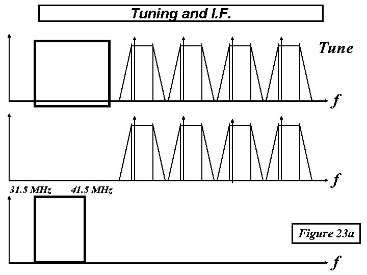
Tuning and I. F. Tune f 31. 5 MHz 41. 5 MHz f Figure 23 a f
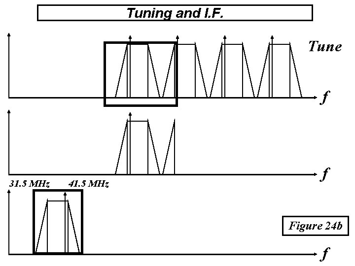
Tuning and I. F. Tune f 31. 5 MHz 41. 5 MHz f Figure 24 b f
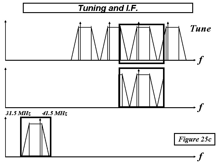
Tuning and I. F. Tune f 31. 5 MHz 41. 5 MHz f Figure 25 c f
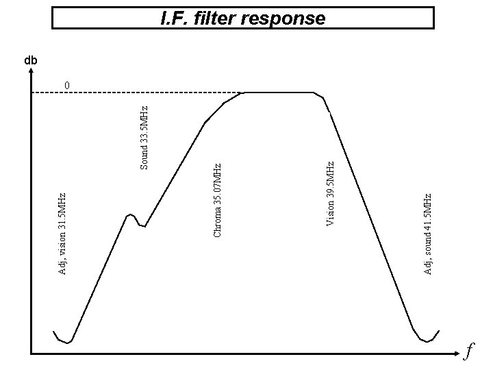
Sound 33. 5 MHz Adj, sound 41. 5 MHz Vision 39. 5 MHz Chroma 35. 07 MHz Adj, vision 31. 5 MHz I. F. filter response db 0 f
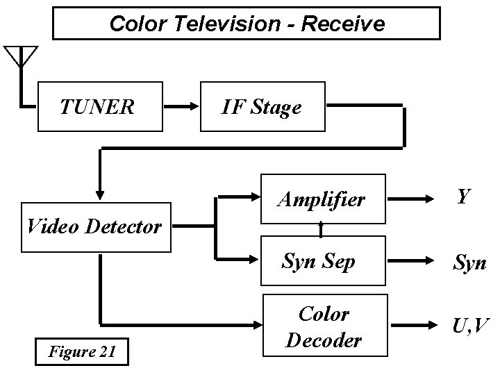
Color Television - Receive TUNER IF Stage Amplifier Y Syn Sep Syn Color Decoder U, V Video Detector Figure 21
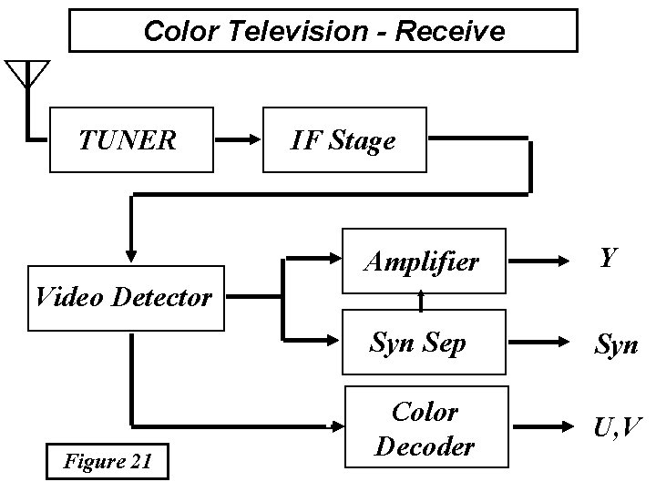
Color Television - Receive TUNER IF Stage Amplifier Y Syn Sep Syn Color Decoder U, V Video Detector Figure 21
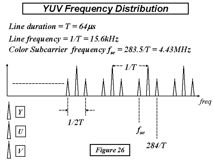
YUV Frequency Distribution Line duration = T = 64 s Line frequency = 1/T = 15. 6 k. Hz Color Subcarrier frequency fsc = 283. 5/T = 4. 43 MHz 1/T freq Y 1/2 T fsc U V Figure 26 284/T
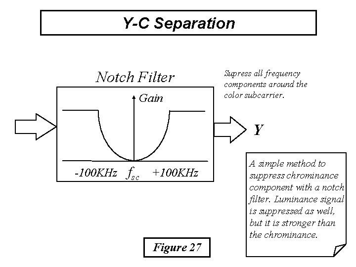
Y-C Separation Notch Filter Gain Supress all frequency components around the color subcarrier. Y -100 KHz fsc +100 KHz Figure 27 A simple method to suppress chrominance component with a notch filter. Luminance signal is suppressed as well, but it is stronger than the chrominance.
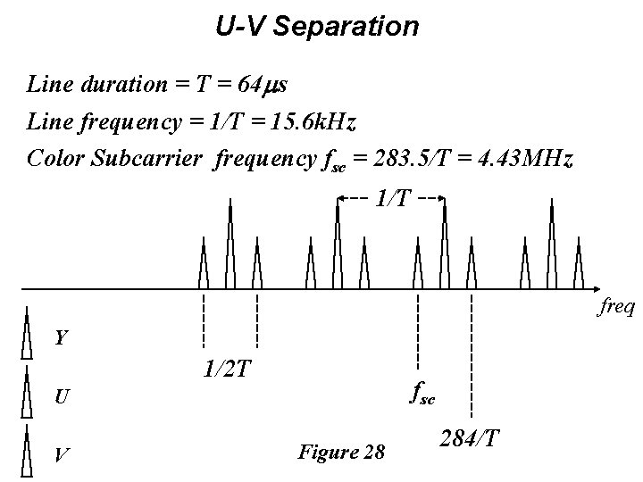
U-V Separation Line duration = T = 64 s Line frequency = 1/T = 15. 6 k. Hz Color Subcarrier frequency fsc = 283. 5/T = 4. 43 MHz 1/T freq Y 1/2 T fsc U V Figure 28 284/T
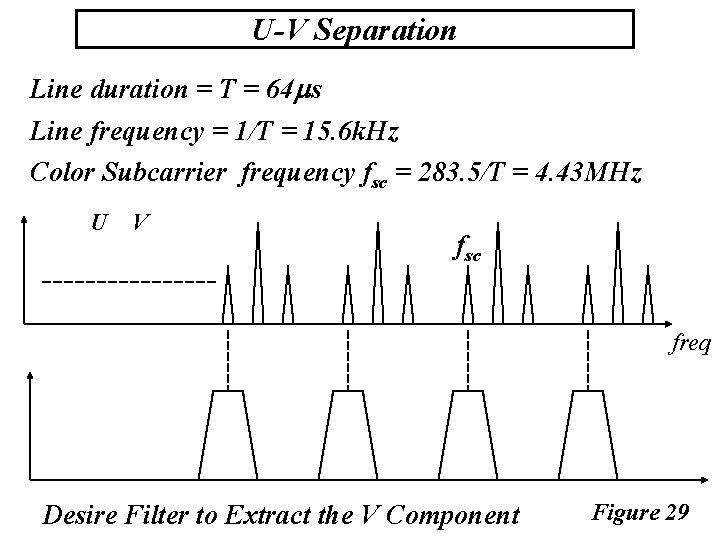
U-V Separation Line duration = T = 64 s Line frequency = 1/T = 15. 6 k. Hz Color Subcarrier frequency fsc = 283. 5/T = 4. 43 MHz U V fsc freq Desire Filter to Extract the V Component Figure 29

U-V Separation Line duration = T = 64 s Line frequency = 1/T = 15. 6 k. Hz Color Subcarrier frequency fsc = 283. 5/T = 4. 43 MHz U V fsc freq Desire Filter to Extract the U Component Figure 30
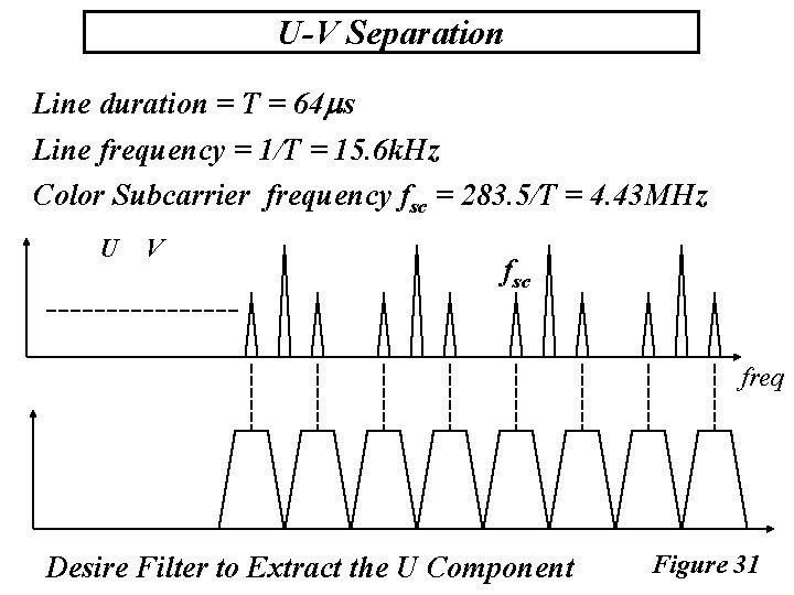
U-V Separation Line duration = T = 64 s Line frequency = 1/T = 15. 6 k. Hz Color Subcarrier frequency fsc = 283. 5/T = 4. 43 MHz U V fsc freq Desire Filter to Extract the U Component Figure 31
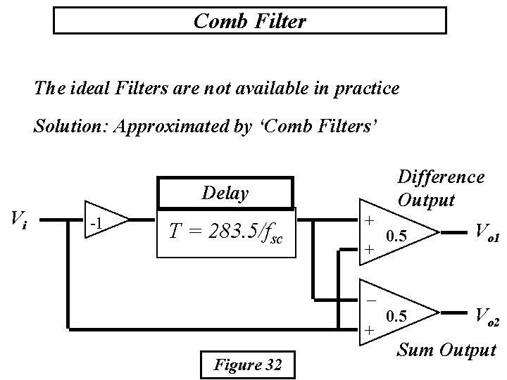
Comb Filter The ideal Filters are not available in practice Solution: Approximated by ‘Comb Filters’ Difference Output Delay Vi -1 T = 283. 5/fsc + + 0. 5 Vo 1 0. 5 Vo 2 _ + Figure 32 Sum Output
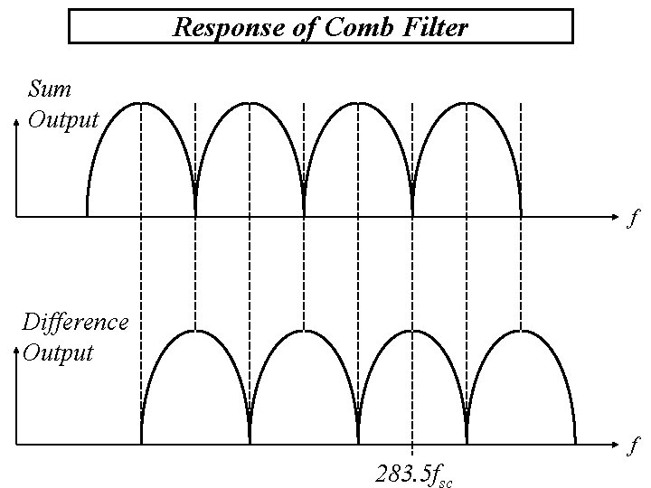
Response of Comb Filter Sum Output f Difference Output f 283. 5 f
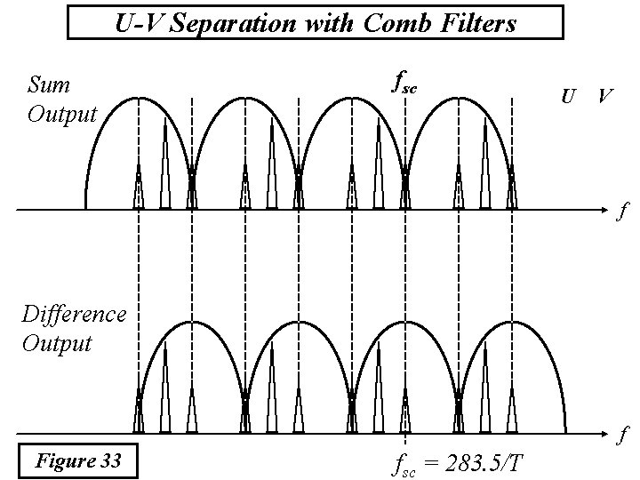
U-V Separation with Comb Filters Sum Output fsc U V f Difference Output f Figure 33 fsc = 283. 5/T
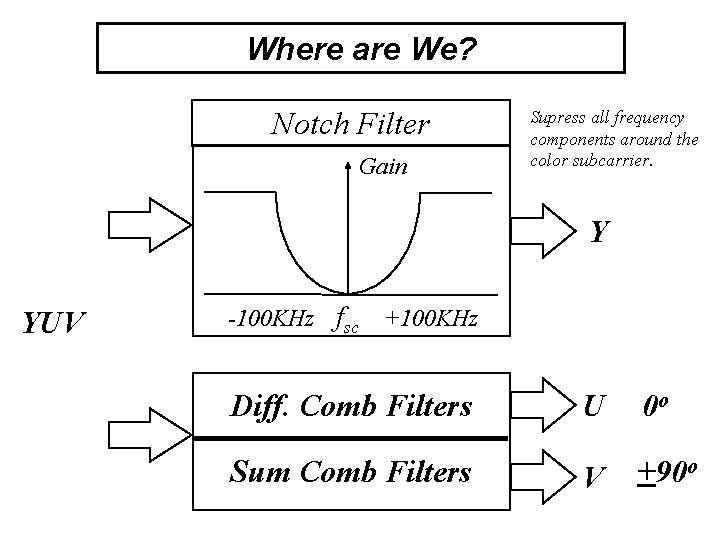
Where are We? Notch Filter Gain Supress all frequency components around the color subcarrier. Y YUV -100 KHz fsc +100 KHz Diff. Comb Filters Sum Comb Filters U 0 o V +90 o

Color Television - Receive TUNER IF Stage Amplifier Y Syn Sep Syn Color Decoder U, V Video Detector
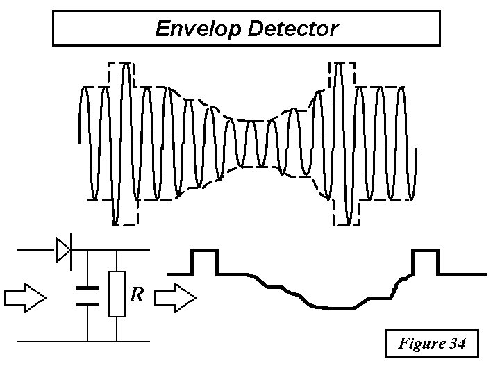
Envelop Detector R Figure 34
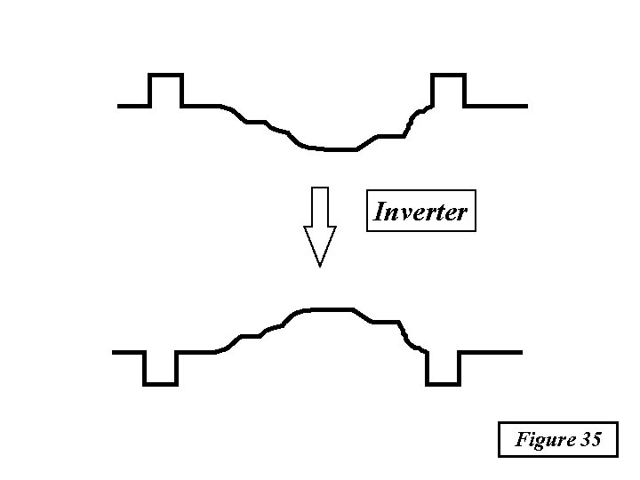
Inverter Figure 35
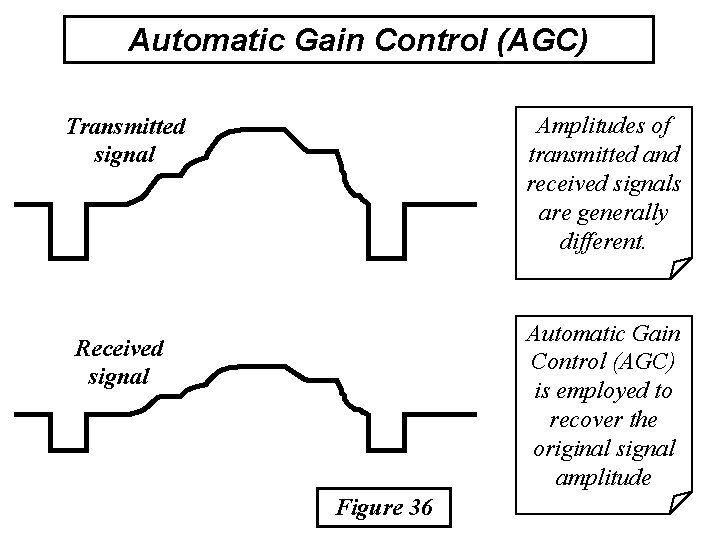
Automatic Gain Control (AGC) Amplitudes of transmitted and received signals are generally different. Transmitted signal Automatic Gain Control (AGC) is employed to recover the original signal amplitude Received signal Figure 36
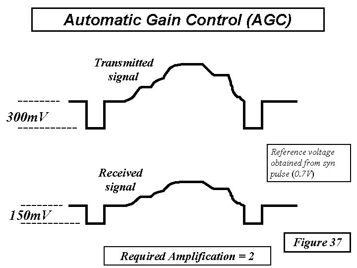
Automatic Gain Control (AGC) Transmitted signal 300 m. V Received signal Reference voltage obtained from syn pulse (0. 7 V) 150 m. V Figure 37 Required Amplification = 2
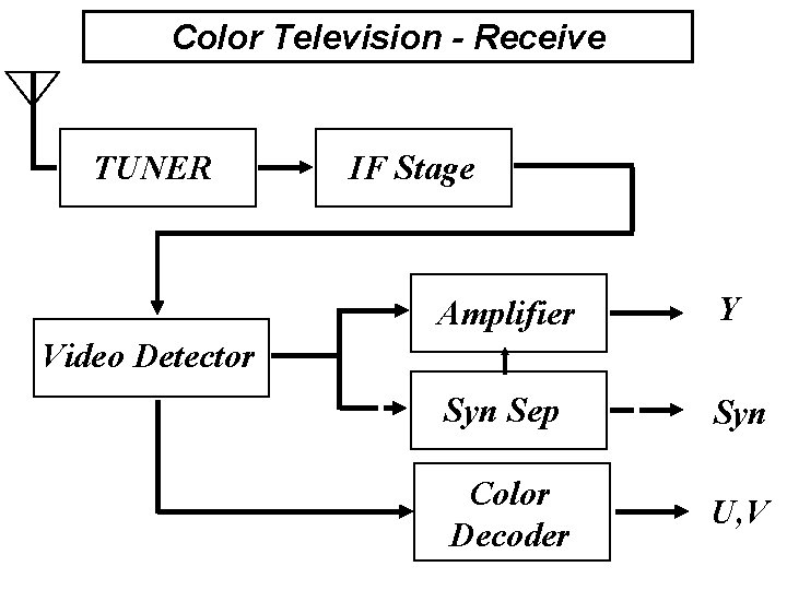
Color Television - Receive TUNER IF Stage Amplifier Y Syn Sep Syn Color Decoder U, V Video Detector
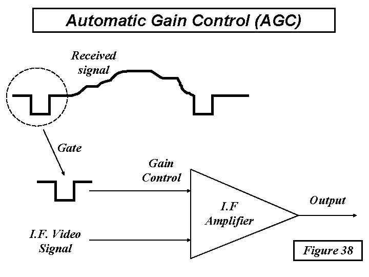
Automatic Gain Control (AGC) Received signal Gate Gain Control I. F. Video Signal I. F Amplifier Output Figure 38
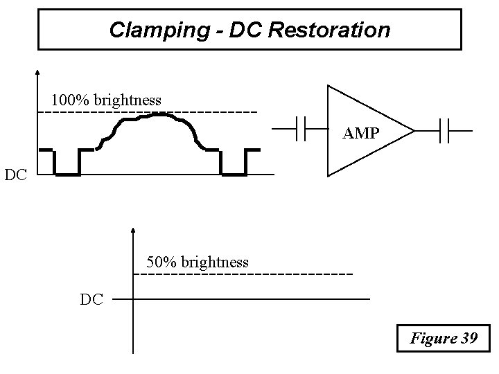
Clamping - DC Restoration 100% brightness AMP DC 50% brightness DC Figure 39
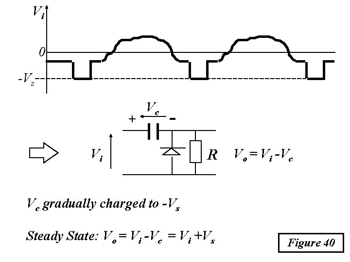
Vi 0 -Vs + Vc - Vi R Vo = Vi -Vc Vc gradually charged to -Vs Steady State: Vo = Vi -Vc = Vi +Vs Figure 40
Color Television - Receive TUNER IF Stage Amplifier Y Syn Sep Syn Color Decoder U, V Video Detector
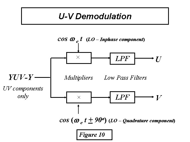
U-V Demodulation cos c t (LO – Inphase component) ´ YUV-Y UV components only Multipliers LPF U Low Pass Filters ´ LPF V cos ( c t + 90 o) (LO – Quadrature component) Figure 10
Problems in U-V Demodulation • The frequency and phase of the Local Oscillators (LO) has to be identical to that in modulation • The LO and its quadrature component are not fully sent to the receiver • Only a few cycles of the LO (color burst) is included at the start of each video line
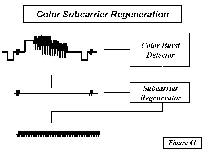
Color Subcarrier Regeneration Color Burst Detector Subcarrier Regenerator Figure 41
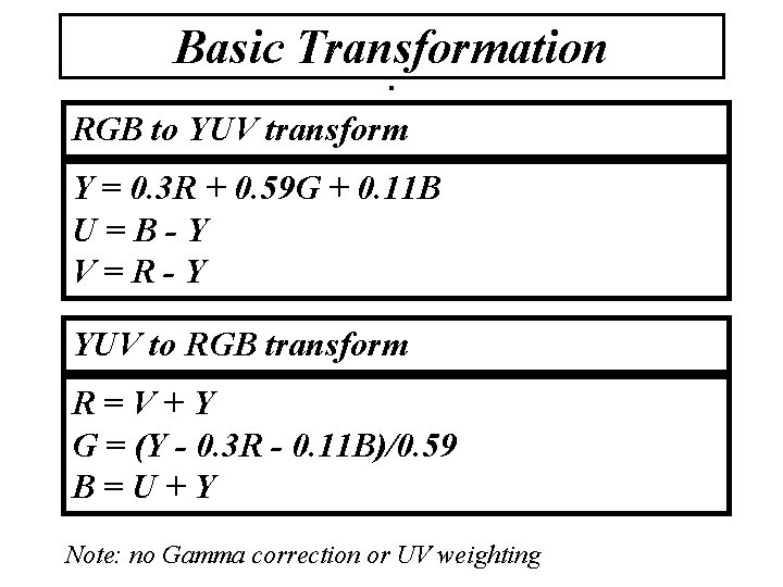
Basic Transformation. RGB to YUV transform Y = 0. 3 R + 0. 59 G + 0. 11 B U=B-Y V=R-Y YUV to RGB transform R=V+Y G = (Y - 0. 3 R - 0. 11 B)/0. 59 B=U+Y Note: no Gamma correction or UV weighting
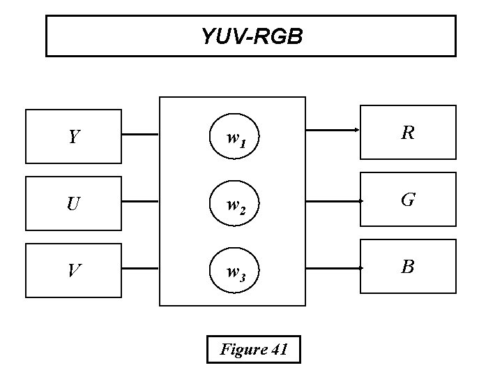
YUV-RGB Y w 1 R U w 2 G V w 3 B Figure 41
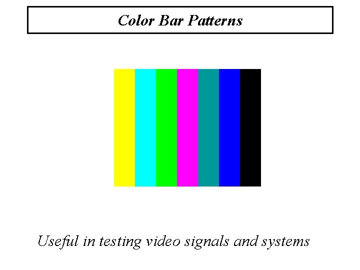
Color Bar Patterns Useful in testing video signals and systems
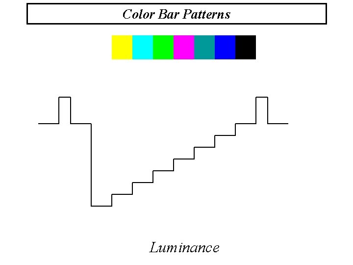
Color Bar Patterns Luminance
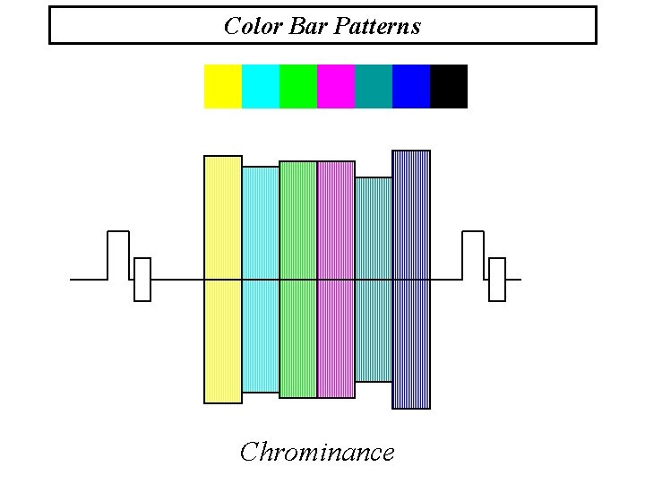
Color Bar Patterns Chrominance
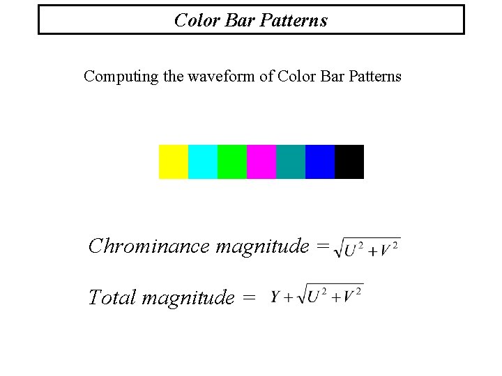
Color Bar Patterns Computing the waveform of Color Bar Patterns Chrominance magnitude = Total magnitude =
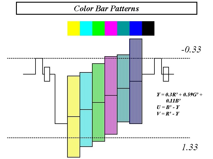
Color Bar Patterns -0. 33 Y = 0. 3 R’ + 0. 59 G’ + 0. 11 B’ U = B’ - Y V = R’ - Y 1. 33

Actual Transformation RGB to YUV transform Y = 0. 3 R’ + 0. 59 G’ + 0. 11 B’ U = 0. 493(B’ - Y) V = 0. 877(R’ - Y) R’, G’ and B’: Gamma corrected color components
- Slides: 44