
Collimation Valery Kapin Workshop on Booster Performance and
Collimation Valery Kapin Workshop on Booster Performance and Enhancements 23 -24 November 2015
Activities & acknowlegments to people involved 1) Booster Collimator Hardware & Control (motion tests): Charles Briegel, Salah Chaurize, Mike Coburn, Vladimir Sidorov, Matt Slabaugh, Todd Sullivan, Rick Tesarek 2) Support for Beam Dynamics Simulations: Valeri Lebedev, Nikolai Mokhov, Igor Rakhno, Sergei Striganov, Igor Tropin 3) Support for task managments: Bill Pellico and Cheng-Yang Tan
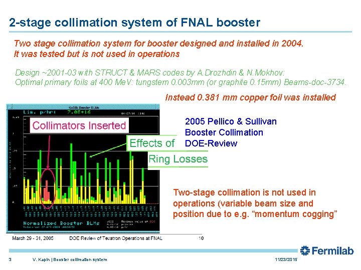
2 -stage collimation system of FNAL booster Two stage collimation system for booster designed and installed in 2004. It was tested but is not used in operations Design ~2001 -03 with STRUCT & MARS codes by A. Drozhdin & N. Mokhov: Optimal primary foils at 400 Me. V: tungstem 0. 003 mm (or graphite 0. 15 mm) Beams-doc-3734. Instead 0. 381 mm copper foil was installed 2005 Pellico & Sullivan Booster Collimation DOE-Review Two-stage collimation is not used in operations (variable beam size and position due to e. g. “momentum cogging” 3 V. Kapin | Booster collimation system 11/23/2015
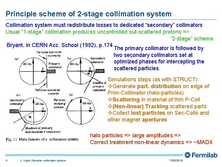
Principle scheme of 2 -stage collimation system Collimation system must redistribute losses to dedicated “secondary” collimators Usual “ 1 -stage” collimation produces uncontrolled out-scattered protons => “ 2 -stage” scheme Bryant, in CERN Acc. School (1992), p. 174 The primary collimator is followed by two secondary collimators set at optimized phases for intercepting the scattered particles. Simulations steps (as with STRUCT): v. Generate part. distribution on edge of Prim-Collimator (halo-particles) v. Scattering in material of thin P-Coll v(Non-linear) Tracking scattered parts v. Collect lost particles on Sec-Colls and other magnet apertures halo particles => large amplitudes => Correct treatment non-linear dynamics => ~MADX 4 V. Kapin | Booster collimation system 11/23/2015
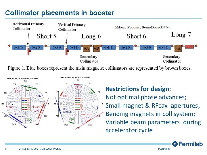
Collimator placements in booster Restrictions for design: Not optimal phase advances; Small magnet & RFcav apertures; Bending magnets in coll system; Variable beam parameters during accelerator cycle 5 V. Kapin | Booster collimation system 11/23/2015
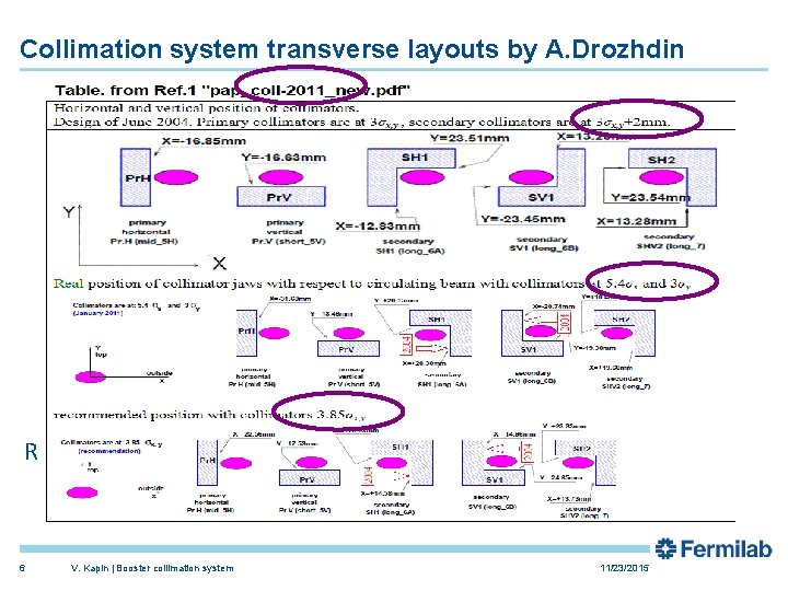
Collimation system transverse layouts by A. Drozhdin RMS scattering angle 6 V. Kapin | Booster collimation system 11/23/2015
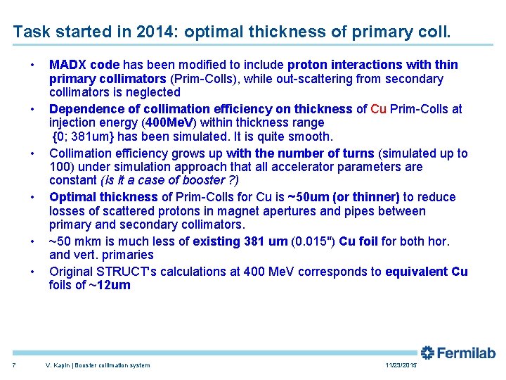
Task started in 2014: optimal thickness of primary coll. • • • 7 MADX code has been modified to include proton interactions with thin primary collimators (Prim-Colls), while out-scattering from secondary collimators is neglected Dependence of collimation efficiency on thickness of Cu Prim-Colls at injection energy (400 Me. V) within thickness range {0; 381 um} has been simulated. It is quite smooth. Collimation efficiency grows up with the number of turns (simulated up to 100) under simulation approach that all accelerator parameters are constant (is it a case of booster ? ) Optimal thickness of Prim-Colls for Cu is ~50 um (or thinner) to reduce losses of scattered protons in magnet apertures and pipes between primary and secondary collimators. ~50 mkm is much less of existing 381 um (0. 015") Cu foil for both hor. and vert. primaries Original STRUCT's calculations at 400 Me. V corresponds to equivalent Cu foils of ~12 um V. Kapin | Booster collimation system 11/23/2015
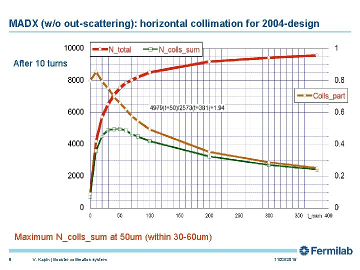
MADX (w/o out-scattering): horizontal collimation for 2004 -design After 10 turns Maximum N_colls_sum at 50 um (within 30 -60 um) 8 V. Kapin | Booster collimation system 11/23/2015
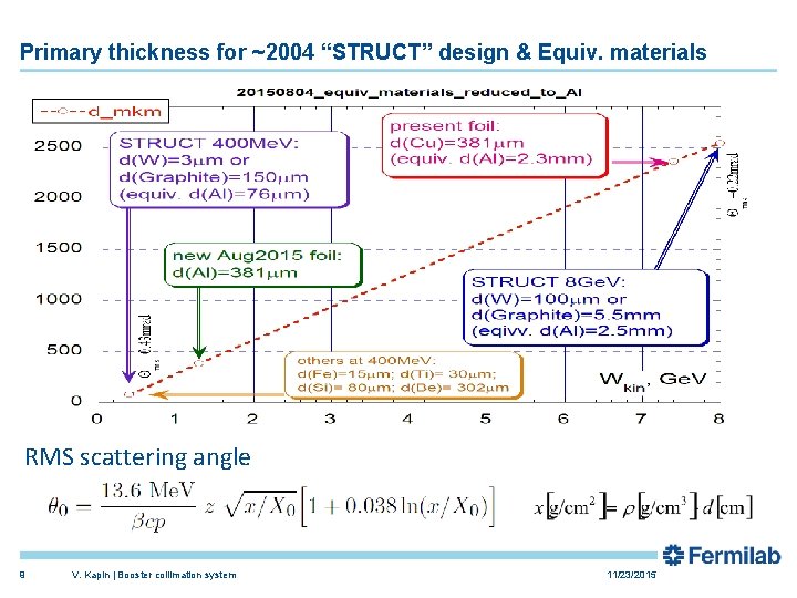
Primary thickness for ~2004 “STRUCT” design & Equiv. materials RMS scattering angle 9 V. Kapin | Booster collimation system 11/23/2015
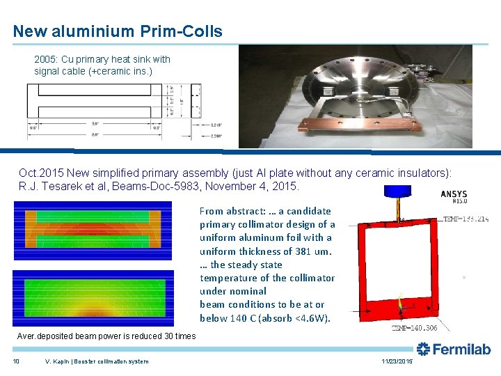
New aluminium Prim-Colls 2005: Cu primary heat sink with signal cable (+ceramic ins. ) Oct. 2015 New simplified primary assembly (just Al plate without any ceramic insulators): R. J. Tesarek et al, Beams-Doc-5983, November 4, 2015. From abstract: … a candidate primary collimator design of a uniform aluminum foil with a uniform thickness of 381 um. … the steady state temperature of the collimator under nominal beam conditions to be at or below 140 C (absorb <4. 6 W). Aver. deposited beam power is reduced 30 times 10 V. Kapin | Booster collimation system 11/23/2015
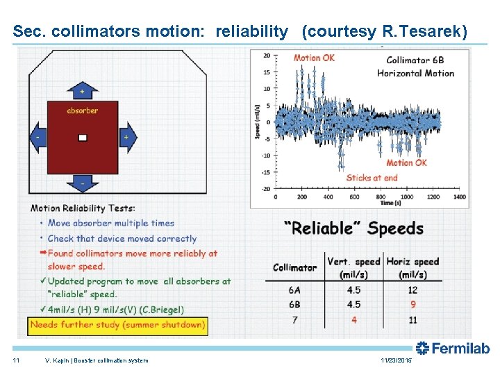
Sec. collimators motion: reliability (courtesy R. Tesarek) 11 V. Kapin | Booster collimation system 11/23/2015
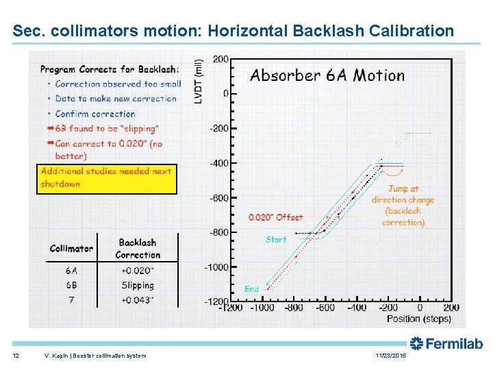
Sec. collimators motion: Horizontal Backlash Calibration 12 V. Kapin | Booster collimation system 11/23/2015
New simulations: upgraded model ØGeneral idea by Lebedev & Mokhov Ø A new simulation approach including out-scattering in Sec-Colls is under development for a correct comparison of two-stage and one-stage collimation in the booster. ØThe proton interactions with Sec-Colls are simulated by MARS (Mokhov's group) and used by MADX tracker as black-boxes. ØCalulations for different collimator layouts (2004 -design; 2011 Drozhdin “real” configuration; and find optimal one) Ø Plans: simulations for different beam sigma and halo sizes ØOptional: Optimizations for existing single-stage scheme 13 V. Kapin | Booster collimation system 11/23/2015
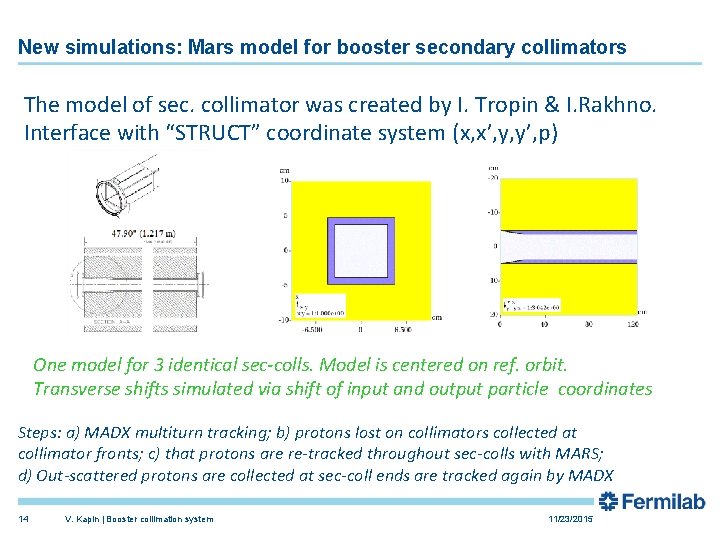
New simulations: Mars model for booster secondary collimators The model of sec. collimator was created by I. Tropin & I. Rakhno. Interface with “STRUCT” coordinate system (x, x’, y, y’, p) One model for 3 identical sec-colls. Model is centered on ref. orbit. Transverse shifts simulated via shift of input and output particle coordinates Steps: a) MADX multiturn tracking; b) protons lost on collimators collected at collimator fronts; c) that protons are re-tracked throughout sec-colls with MARS; d) Out-scattered protons are collected at sec-coll ends are tracked again by MADX 14 V. Kapin | Booster collimation system 11/23/2015

Example of 1 stage horizontal collimation on COL 1 15 V. Kapin | Booster collimation system 11/23/2015
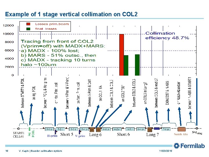
Example of 1 stage vertical collimation on COL 2 16 V. Kapin | Booster collimation system 11/23/2015
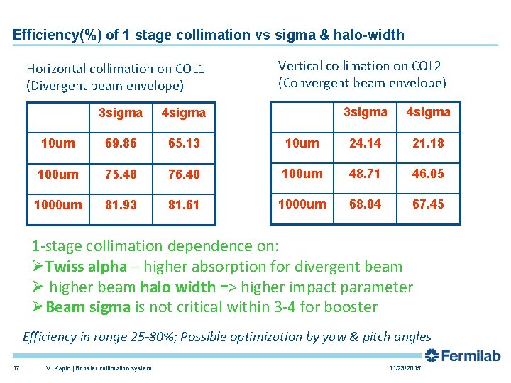
Efficiency(%) of 1 stage collimation vs sigma & halo-width Horizontal collimation on COL 1 (Divergent beam envelope) Vertical collimation on COL 2 (Convergent beam envelope) 3 sigma 4 sigma 10 um 24. 14 21. 18 76. 40 100 um 48. 71 46. 05 81. 61 1000 um 68. 04 67. 45 3 sigma 4 sigma 10 um 69. 86 65. 13 100 um 75. 48 1000 um 81. 93 1 -stage collimation dependence on: ØTwiss alpha – higher absorption for divergent beam Ø higher beam halo width => higher impact parameter ØBeam sigma is not critical within 3 -4 for booster Efficiency in range 25 -80%; Possible optimization by yaw & pitch angles 17 V. Kapin | Booster collimation system 11/23/2015
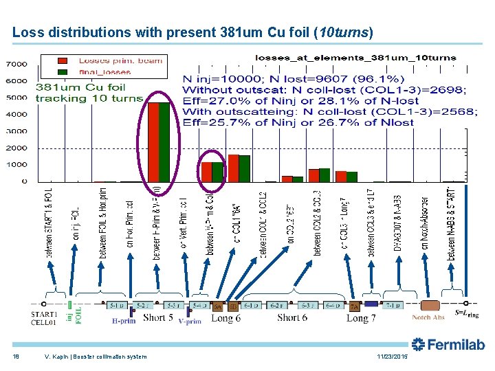
Loss distributions with present 381 um Cu foil (10 turns) 18 V. Kapin | Booster collimation system 11/23/2015
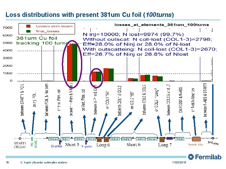
Loss distributions with present 381 um Cu foil (100 turns) 19 V. Kapin | Booster collimation system 11/23/2015
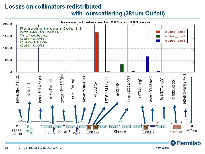
Losses on collimators redistributed with outscattering (381 um Cu foil) 20 V. Kapin | Booster collimation system 11/23/2015

Loss distributions with new 381 um Al “ 50 um Cu” foil (10 turns) 21 V. Kapin | Booster collimation system 11/23/2015
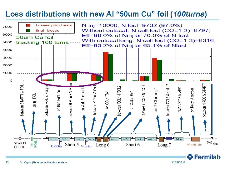
Loss distributions with new Al “ 50 um Cu” foil (100 turns) 22 V. Kapin | Booster collimation system 11/23/2015
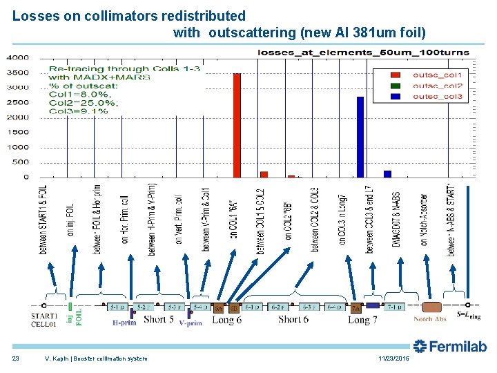
Losses on collimators redistributed with outscattering (new Al 381 um foil) 23 V. Kapin | Booster collimation system 11/23/2015
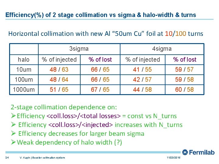
Efficiency(%) of 2 stage collimation vs sigma & halo-width & turns Horizontal collimation with new Al “ 50 um Cu” foil at 10/100 turns 3 sigma 4 sigma halo % of injected % of lost 10 um 48 / 63 66 / 65 41 / 55 59 / 57 100 um 48 / 64 66 / 65 42 / 57 59 / 58 1000 um 51 / 65 67 / 65 44 / 58 60 / 58 2 -stage collimation dependence on: ØEfficiency <coll. loss>/<total losses> = const vs N_turns Ø Efficiency <coll. loss>/<injected> increases with N_turns Ø Efficiency decreases for larger beam sigma ØWeak dependency of halo width (? ) 24 V. Kapin | Booster collimation system 11/23/2015
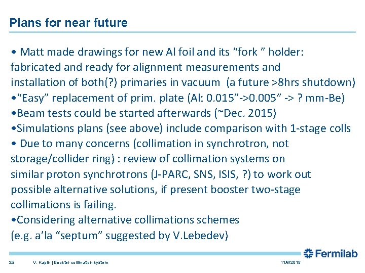
Plans for near future • Matt made drawings for new Al foil and its “fork ” holder: fabricated and ready for alignment measurements and installation of both(? ) primaries in vacuum (a future >8 hrs shutdown) • “Easy” replacement of prim. plate (Al: 0. 015”->0. 005” -> ? mm-Be) • Beam tests could be started afterwards (~Dec. 2015) • Simulations plans (see above) include comparison with 1 -stage colls • Due to many concerns (collimation in synchrotron, not storage/collider ring) : review of collimation systems on similar proton synchrotrons (J-PARC, SNS, ISIS, ? ) to work out possible alternative solutions, if present booster two-stage collimations is failing. • Considering alternative collimations schemes (e. g. a’la “septum” suggested by V. Lebedev) 25 V. Kapin | Booster collimation system 11/9/2015
Supporting slide

Sec. collimators motion: 6 B Horizontal motion 27 V. Kapin | Booster collimation system 11/23/2015
- Slides: 27