Coherence Spatial Temporal Interference Youngs Double Slit Experiment

Coherence: Spatial, Temporal Interference: Young’s Double Slit Experiment Fringes of Equal Inclination Fringes of Equal Thickness 1

Coherence 2

Concept of coherence is related to stability or predictability of phase Spatial coherence describes the correlation between signals at different points in space. Temporal coherence describes the correlation between signals at different moments of time. 3

Electric field distribution around the focus of a laser beam with perfect spatial and temporal coherence. A laser beam with high spatial coherence, but poor temporal coherence. A laser beam with poor spatial coherence, but high temporal coherence. 4 4

Quantifying Coherence Physically, monochromatic sources are fictitious. Band of frequencies = Wave train Many sinusoidal nearby frequencies are needed to construct the above 5
 = [Sin t + Sin(1. 01 t) + Sin (1. 02 t) +")
y(t) = [Sin t + Sin(1. 01 t) + Sin (1. 02 t) + Sin(1. 03 t) + Sin (1. 04 t) + Sin (1. 05 t) + Sin (1. 06 t) + Sin (1. 07 t) + Sin (1. 08 t)]/9 0 < t < 800 6

Quantifying Coherence Temporal coherence: Coherence time: The coherence time is the time over which a propagating wave may be considered coherent. In other words, it is the time interval within which its phase is, on average, predictable. : Spectral width of the source in units of frequency. Coherence length: The coherence length is the coherence times the vacuum velocity of light, and thus also characterizes the temporal (not spatial!) coherence via the propagation length (and thus propagation time) over which coherence is lost. 7

Red Cadmium = 10 9 Hz, Yellow Sodium 10 = 10 Hz, He-Ne Laser = 10 6 = 6438 Å 30 cm = 5893 Å 3 cm = 6328 Å Hz, 300 m 8

A plane wave with an infinite coherence length. Since there are two transverse dimensions, we can define a coherence area (Ac). 9
 and infinite coherence length. 10")
A wave with a varying profile (wavefront) and infinite coherence length. 10

A wave with a varying profile and finite coherence length. The spatial coherence depends on the emitter size and its distance. where d is the diameter of the light source and D is the distance. 11

The wave with finite coherence length is passed through a pinhole. The emerging wave has infinite coherence area. The coherence length (or coherence time) are unchanged by the pinhole. 12

Interference of water waves Interference is the effect produced by the superposition of waves from two coherent sources passing through the same region.

Interference of water waves Two wave sources are said to be coherent: - if the phase difference between the sources is constant, - if they have same frequency, - if the two waves have comparable amplitudes. The interference pattern produced in a ripple tank using two sources of circular waves which are in phase with each other.

Constructive & destructive interference The two sources S 1 and S 2 are in phase and coherent. Therefore, the wavelengths of waves from S 1 and S 2 are the same, say λ.

Conditions of Interference 16

Coherent Sources Constant phase difference Such sources may or may not be in step but are always marching together 17

Temporal coherence The interval over which the light wave resembles a sinusoid is the measure of its temporal coherence. Coherence Time of Radiation The average time interval during which the light wave oscillates in a predictable way is known as coherence time of radiation. 18

Spatial extent over which the light wave oscillates in a regular predictable way is the coherent length 19

Temporal Coherence 20

Spatial Coherence 21

Interference of light from two bulbs? 22

White Light Interference 23
 interfere to form a pulse if they")
Waves of different frequencies (i. e. colors) interfere to form a pulse if they are coherent. 24

Spectrally incoherent light interferes to form continuous light with a randomly varying phase and amplitude 25

Optical Interference Optical interference corresponds to the interaction of two or more light waves yielding a resultant irradiance that deviates from the sum of component irradiance. • Wavefront splitting • Amplitude splitting Wavefront Division: Involves taking one wavefront and dividing it up into more than one wave. Eg: Young’s double slit interference; Diffraction grating Amplitude Division: Involves splitting a light beam into two beams at a surface of two media of different refractive index. 26 Eg: Michelson interferometer

• Light waves interfere with each other much like mechanical waves do. • All interference associated with light waves arises when the electromagnetic fields that constitute the individual waves combine • LINEAR SUPERPOSITION! 27

Resultant 28

Interference Animation http: //www. acs. psu. edu/drussell/demos/superposition. html The angular spacing of the fringes, θf, is given by: where d is the separation between slits 29

30

Irradiance Strictly speaking irradiance is power/area. And intensity is power/solid angle. 31

32

Interference term 33

34

Time average gives: The interference term The phase difference arising from a combined path length and initial phase difference. 35

36

37

For maximum irradiance 1 Total constructive interference 38

For minimum irradiance 1 Total destructive interference 39

Components out of phase Constructive Interference 40

Components 90 o out of phase 41

Destructive Interference 42

Twin Source Interference Pattern For I 1=I 2 43

For the spherical wave emitted by two sources, in-phase at the emitter 44

45

Photo shows an interference pattern by two holes 46

Interference by two plane polarized light wave For constructive interference For destructive interference 47

Wavefront splitting Interferometer Young’s Double Slit Experiment 48

Wavefront splitting interferometer Young’s Double Slit Diffraction Grating Amplitude splitting interferometer Fringes of equal inclination Fringes of equal thickness 49

Young’s Double Slit Experiment 50

Young’s double slit 51

Path difference: 52

D 53

Path difference: For a bright fringe, m: any integer http: //www. acs. psu. edu/drussell/demo s/superposition. html For a dark fringe, 54

Destructive interference 55

Constructive Interference 56

Double slit: A closer look Curves of equal-path difference are Hyperboloids of revolution

http: //fp. optics. arizona. edu/milster/505%20 Lecture/Lecture%20 Notes%20 and%20 Slides/Chapter%204%20 Basic%20 Interference/OLD%20 NOTES/Basic%20 Interference%20 -%20 Part%20 B%20. pdf

Transverse Section: Straight fringes

Longitudinal section: Circular fringes

Transverse section –Straight fringes P S x q q d O N S D 62

Path difference The distance of mth bright fringe from central maxima Fringe separation/ Fringe width 63

Interference Animation The angular spacing of the fringes, θf, is given by: where d is the separation between slits 64
 65")
For two beams of equal irradiance (I 0) 65
 Maximum and adjacent minimum of the fringe system 66")
Visibility of the fringes (V) Maximum and adjacent minimum of the fringe system 66

Photograph of real fringe pattern for Young’s double slit 67

The two waves travel the same distance – Therefore, they arrive in phase S' S 68

• The upper wave travels one wavelength farther –Therefore, the waves arrive in phase S' S 69

• The upper wave travels one-half of a wavelength farther than the lower wave. This is destructive interference S' S 70

Uses for Young’s Double Slit Experiment • Young’s Double Slit Experiment provides a method for measuring wavelength of the light • This experiment gave the wave model of light a great deal of credibility. 71

Longitudinal section –Circular fringes P rn N O q S S d D 72

P rn N S q d O S D At the central spot, Path difference = d For central bright fringe: d = mo λ 73

P rn N For small m S q d O S D Radius of nth bright ring 74

Pohl’s fringes Longitudinal Section Thin mica plate

Fresnel double mirror P 1 P 2 76

Fresnel biprism 77

Lloyd’s mirror 78

Billet’s split lens 79

Wavefront splitting interferometers • Young’s double slit • Fresnel double mirror • Fresnel double prism • Lloyd’s mirror 80

For a bright fringe, For a dark fringe, Extra phase difference ±p in Lloyd’s mirror 81

1. Optics Author: Eugene Hecht Class no. 535 HEC/O Central library IIT KGP 82

Division of Amplitude 83

Thin Film Interference n 2 nf n 1 C C t t D D i t A d B A B

Optical path difference for the first two reflected beams C i D i A t t t B AC = 2 d tan t

Path Difference

Consider a soap film: n 1 = n 2 = n Phase shift (in the case of external reflection) For n 1 > nf > n 2, or n 1 < nf < n 2, the ±π phase shift will not be present
 Condition for minima( = (2 m+1)π) Note: Odd")
Condition for maxima( = 2 mπ) Condition for minima( = (2 m+1)π) Note: Odd and even multiple of ( f /4)

-Since d is constant, the locus of each interference fringe is determined by a constant value of which depends on a constant angle i. -This gives circular fringe around the centre point. -An extended source produces a range of constant values at one viewing position so the complete pattern is obviously a set of concentric fringes formed at infinity. -These are fringes of equal inclination and are called Haidinger fringes.

Fringes of equal inclination

Haidinger’s Bands: Fringes of equal inclination n 1 Beam splitter d n 2 P x f Focal plane Extended source PI P 2 Dielectric slab

Fringes of equal thickness - Fringes observed when optical thickness nfd is dominant rather than i. - Ex: Oil slicks - Each fringe is the locus of all points in the film for which the optical thickness is a constant. - In general nf does not vary, so the fringes correspond to regions of constant film thickness. - When the thickness d is not constant and the faces of the slab form a wedge. The interfering rays are not parallel but meet at points (real or virtual) near the wedge. - The resulting interference fringes are localized near the wedge.

Fizeau Fringes Beam splitter n Extended source d =x : Wedge angle n 2 x n

Wedge between two plates 1 2 glass t D air x Path difference = 2 t Phase difference = 2 kt - Maxima 2 t = (m + ½) o/n Minima 2 t = m o/n (phase change for 2, but not for 1)
")
Fizeau Fringes: fringes of equal thickness Conditions for maximum (For small values of i) d is the thickness at a particular point d =x These are termed Fizeau fringes.

Consecutive fringes are separated by

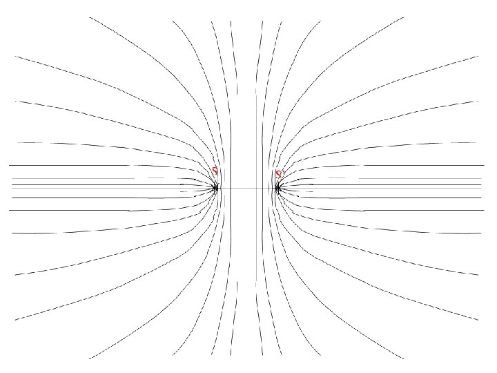
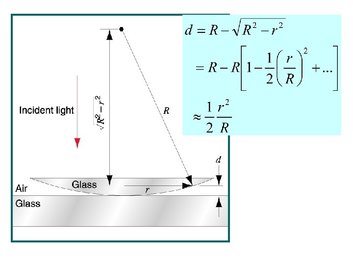
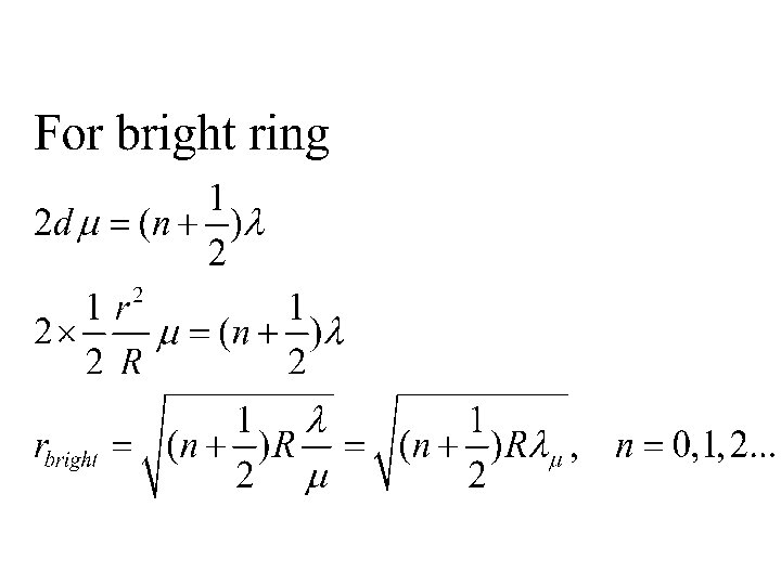
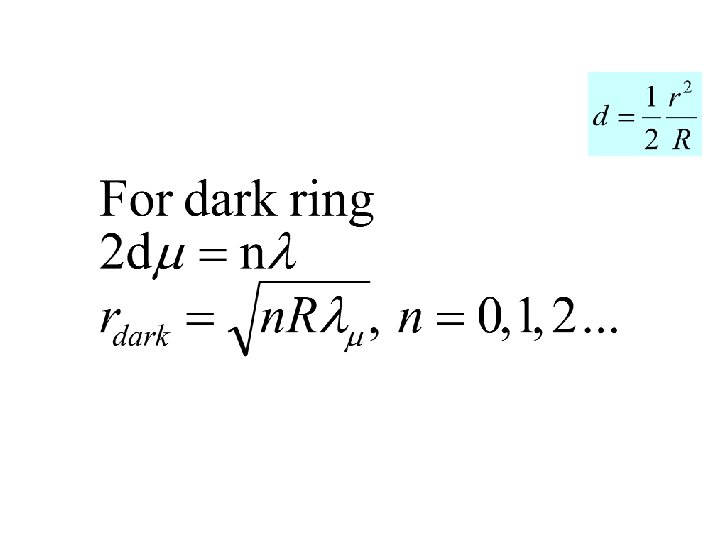
Newton’s Ring Ray 1 undergoes a phase change of 180 on reflection, whereas ray 2 undergoes no phase change R = radius of curvature of lens x = radius of Newton’s ring

Reflected Newton’s Ring

Thin Wedge

Enlarged wedge

Colour of thin oil films

Thin oil film
 Michelson, Fabry-Perot. (Thickness is constant, but")
Fringe system of constant inclination (Haidinger Fringe Pattern) Michelson, Fabry-Perot. (Thickness is constant, but variation of angles gives fringes of different order (m)). Fringe system of constant thickness (Fizeau Fringe pattern) Newton’s ring, Thin wedge film, Uneven thin oil film. (Variation of thickness gives fringes of different order). Order of Fringe Haidinger Pattern: (Ex: Fabry-Perot Interferometer) Central region corresponds to maximum value of m. Fizeau Pattern: (Ex: Newton’s rings) Central region corresponds to minimum value of m.
- Slides: 107