CMPE 252 A Computer Networks Chen Qian Computer


 v Each vertex has the same")
 : : RRG(n, r) q Procedure to modify RRG(n-1, r) to")


 Small World 2 D")


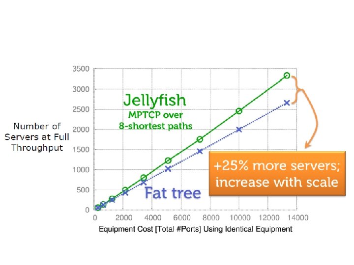
 highest throughput q Jellyfish is only little bit worse.")


: SAB 1 C 1 DT, SAB")

 http: //blogs. citrix. com/2013/ 08/23/networking-beyondtcp-the-mptcp-way/")


 • How to build a flexible data")


- Slides: 73
CMPE 252 A : Computer Networks Chen Qian Computer Engineering UCSC Baskin Engineering Lecture 12 1
Jellyfish: Networking Data Centers Randomly Paper by Ankit Singla, et. al. NDSI 2012. Some figures are from slides presented by Chi-Yao Hong, UIUC.
q Facebook v ‘Add capacity On a DAILY BASIS’ q Amazon http: //news. netcraft. com/archives/2013/05/20/ amazon-web-services-growthunrelenting. html
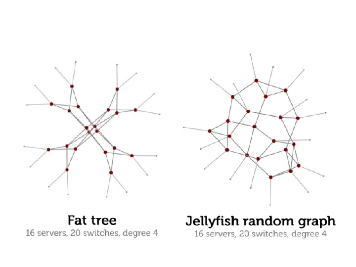
Fat-Tree Topology l a t n e m e r ? c ? n h I t w o gr
Structured networks
Fat tree: Structure VS Limit q N_switches: • 3 -level Fat tree : 5 k 2/4 q for fat tree using k-port switches v 24 -port 3456 hosts v 32 -port 8192 hosts v 48 -port 27648 hosts q What for 10000 hosts? q Over utilize? Leave unused ports?
Goals q Bandwidth & Capacity v Better VM Placement Reduce Traffic v Better Topology Avoid Bottleneck v Robustness Failure resistance q Flexbility: Incremental Expansion v Easy to add VM v Easy to remove VM
Jellyfish : no structure
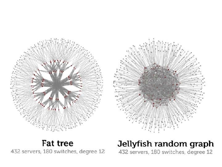
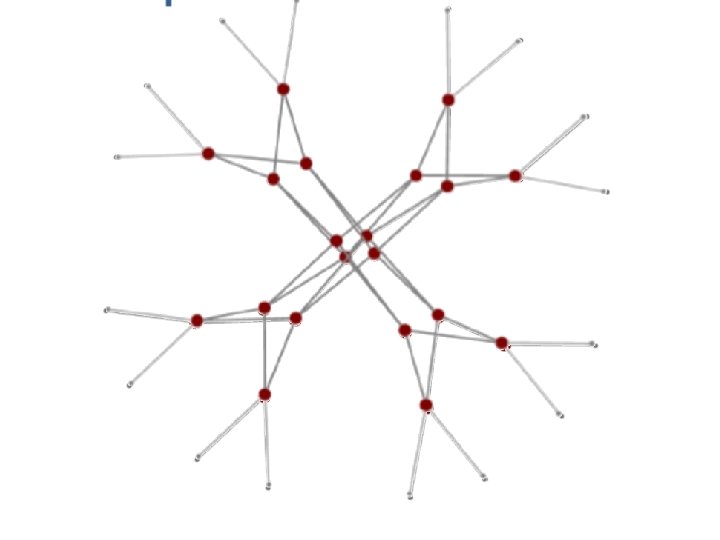
q Topology of jellyfish networks for 432 severs, 180 switches, degree = 12
Random graph q Regular Graph v RG(n, r) v Each vertex has the same degree r q Random Regular Graph v Random sampled from all RG(n, r) v Hard to generate • Question: How to generate?
Not-so-uniform Random-RG(n, r) : : RRG(n, r) q Procedure to modify RRG(n-1, r) to RRG(n, r) q r=3 q RRG(4, 3) q RRG(5, 3)
Goals q Bandwidth & Capacity v Better VM Placement Reduce Traffic v Better Topology Avoid Bottleneck q Incremental Expansion v Easy to add VM v Easy to remove VM
About the Evaluation q bisection bandwidth: Theoretical calculation for RRG, v Bollobas’ theoretical lower bounds q Throughput: random permutation traffic v Each host choose one to send (at full speed)
Jellyfish VS LEGUP
Vs. Fat. Tree Bisection bandwidth Jellyfish: larger B-bandwidth using same # switches & servers Jellyfish: more servers under the same B-bandwidth and # switches
Lower cost
Better failure resilience
Larger Throughput
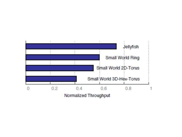
Jellyfish vs. Small World Ring (2 reg + 4 rand) Small World 2 D Torus (4 reg + 2 rand) q Smallworld: grid + random Small World 3 D Hexagon Torus (5 reg + 1 rand)
Reason of better performance q
Better than jellyfish ? ? ? q More hosts using same # of switches? q Connecting more switches , each of which has same # ports, (limit the diameter) q How many switches can be connected , with 3 switch-to-switch ports , and switch-toswitch path length <= 2? q Petersen Graph
Degree-diameter-graph
q Degree-Diameter Graph have (nearly) highest throughput q Jellyfish is only little bit worse.
But… q Practical constraint: v Routing / Congestion Control v Cable
Routing & Congestion Control , d e tiliz q Utilize capacity without structure ully u f s i ity c q no layers! a p a c e l b a il a v a l l a If q Routing : v ECMP: fail to provide large path diversity v K shortest path: q Congestion Control v TCP/ multipath TCP
K-shortest path q Different Path v S-e 1 -e 2 -e 3 -…ex. . . -en-T v S-e 1 -e 2 -e 3 -…ey…-em-T q Algorithm to find 2 nd-shortest path: v Find a shortest path P from S to T in G v For each e in P v …Remove e from G v …Calculate shortest path on G , namely SP(e) v …add e back to Graph v Return 2 min(SP(e)) O(k N*Shortest. Path(N))
K-shortest path forwarding q Shortest Paths (S, T): SAB 1 C 1 DT, SAB 2 C 2 DT, SAB 3 C 2 DT, S (S, T) A A A (A, T) B 1 B 2 B 3 B A C D T (B 1, T) C 1 A A (B 4, T) C 2 A A
Inter-switch link’s path count in ECMP and k-shortestpath routing for random permutation traffic at the server-level on a typical Jellyfish of 686 servers. For each link, we count the number of distinct paths it is on.
Multi Path TCP (MPTCP) http: //blogs. citrix. com/2013/ 08/23/networking-beyondtcp-the-mptcp-way/
q Packet simulation results for different routing and congestion control protocols
cabling q Jellyfish uses 20% less # cables ,
Cabling in large data centers q Topology generated automatically, q Cables connected manually. . ( 10% of cost) q Error detect : link-layer discovery protocol.
Jellyfish of Jellyfish q Restrict some connections in pod q Result: 2 -layered random Graph
Jellyfish of Jellyfish q Restrict some connections in pod q Result: 2 -layered random Graph
Cables between pods can be aggregated
Conclusion q Bandwidth & Capacity q Incremental Expansion q Lower Cost q Limitation: slow to compute forwarding paths. Large forwarding tables.
Space Shuffle: A Scalable, Flexible, and High-Bandwidth Data Center Network Ye Yu and Chen Qian
Motivation: Goals of Data Center Design High-bandwidth • Data center applications generates high internal & external communication Flexibility • Adding servers and expanding network bandwidth incrementally. Scalability • Routing and Forwarding should rely on small forwarding state.
Motivation: Existing Data Center Architectures Network Bandwidth Fat. Tree No shortest paths. Good [SIGCOMM’ 08] Does not support multipath well. SWDC Fair [SOCC’ 11] Jellyfish [NSDI’ 12] Incremental Growth (Flexible) Forwarding State per switch (Scalability) No Fixed Greedy Routing Yes Constant Better than Large and grows Random Interconnection Yes Fat. Tree & SWDC fast K-shortest path routing is inefficient. Big forwarding state.
Motivation: Goal of Space Shuffle (S 2) • How to build a flexible data center architecture that achieves high-throughput and scalability ? • Approach: Greedy routing on random interconnection. • Challenges: • How to build a random interconnection that enables greedy routing? • How does the greedy routing protocol achieve high-throughput and near-optimal path length?
Outline • Motivation • Space Shuffle Data Center Topology • The Routing Protocol in Space Shuffle Data Center • Discussion & Evaluation
S 2 Topology Construction -Assign Servers • Servers and Top-Of-Rack switches. • Uniformly assign servers to switches. • Connect servers to switches. • The rest ports are used for inter-switch connections.
S 2 Topology Construction: -Virtual Coordinates •
S 2 Topology Construction: -Virtual Spaces • Switch ID Coor. 1 A B C D E F G H I 0. 05 0. 13 0. 23 0. 36 0. 42 0. 51 0. 63 0. 78 0. 91 Coor. 2 0. 17 0. 62 0. 91 0. 42 0. 53 0. 58 0. 73 0. 26 0. 97 0 0 A I H C G Space 1 G F C B E D I A Space 2 B F E D H
S 2 Topology Construction: -Connect the switches C I A G H B F E D I A I B H A B C I C A • A switch is physically H connected to switches C G Space 1 Space 2 DH that are adjacent to itself G in at least one space G B D F D E E F F E
S 2 Topology Construction: -Connect the switches • A I B H C D G F E
S 2 Topology Construction: -Deploy-as-a-whole Construction • Assign Step 1 hosts / switches • Generate coordinates Step 2 (randomly) • Wire the network according to the Step 3 coordinates.
S 2 Topology Construction: -Incremental Construction • Add a new switch T into existing S 2 network • Assign coordinate for T. • For each space: • Place T on the circle • Find the switch SL and SR on the left/right side of T • Disconnect SL, SR SR • Connect T, SL; Connect T, SR SL T
Outline • Motivation • Space Shuffle Data Center Topology • The Routing Protocol in Space Shuffle Data Center • Discussion & Evaluation
Routing Protocol in S 2: -Routable Address • Step 1 Step 2 • •
Routing Protocol in S 2 -Definition of Distance • Switch Coor. 1 Coor. 2 A C 0. 05 0. 23 0. 17 0. 91 CD(0. 05, 0. 23) = |0. 23 -0. 05| = 0. 18 CD(0. 17, 0. 91) = 0. 17+(1 -0. 91) = 0. 28 MCD 2(A, C) = min(0. 18, 0. 28)= 0. 18 0 0 A C C A
Routing Protocol in S 2 -Forwarding Decision using MCD • Switch MCD to the destination The switch with minimum H 0. 35 MCD to the destination gets the pac A 0. 18 D 0. 13 Minimum of Minimum CD: Greediest G 0. 19 I 0. 06
Routing Protocol in S 2 -Multipath • Next-hop candidates: all neighbor switch with smaller MCD to the destination than current. Switch MCD to the destination Current 0. 3 Neighbor 1 0. 5 Neighbor 2 the packet goes to the 0. 1 destination Neighbor 3 0. 2 as long as MCD decreases Neighbor 4 0. 4 • It provides enough path diversity by doing such selection only on the first switch of the path.
Routing Protocol in S 2: -Balanced Random Coordinates More traffic on links with small end-to-end MCD values. Uniformly distributed coordinates improves load balancing.
Outline • Motivation • Space Shuffle Data Center Topology • The Routing Protocol in Space Shuffle Data Center • Discussion & Evaluation
Evaluation • Topology property • Routing efficiency • Practical throughput
Evaluation -Topology Property Bisection bandwidth S 2 and Jellyfish: Flexible Fat. Tree: Fixed # of switches S 2 & Jellyfish topologies share similar theoretical throughput, better than Fat. Tree.
Evaluation -Routing Table Length • 10 inter-switch ports
Evaluation -Routing Path Length SWDC: long routing paths, lower throughput. S 2: near-optimal routing paths Jellyfish: optimal paths , expensive 12 inter-switch ports
Evaluation -Practical Throughput Greedy routing of S 2 exploits the path diversity. S 2 achieves near-Jellyfish S 2 & Jellyfish throughput. both outperform SWDC 250 -switch 500 -host network
Comparing S 2 with Jellyfish Construction Routing S 2 Coordinates Ring Topology Greediest Jellyfish Generate ‘Almost’ Random Regular Graph K-shortest path Hard to fit a Jellyfish topology into a routable coordinate space
Key-based Routing: -Definition • Key-value stores • https: //www. facebook. com/photo. php? fbid= 677700648959984 • Key-based Routing: route to the destination using the key of the content. (Not necessarily to know the IP) • IP-based Routing: IP of the destination.
Key-based Routing: -Delivery Guarantee • For any destination coordinate X, greediest routing will route the packet to a switch S, • S is closest to X in at least one space. • Solution: Keep one replica in each of fist r spaces and route using MCDr , r <=L • For data a with key Ka, use global hash function H to calculate the destination coordinate X=H(Ka) • In each of the r spaces, the access switch of the server for a is selected using global hash function H(Ka)
S 2 Topology Construction-Overview • H servers and N Top-Of-Rack switches. • Uniformly assign switches to servers. • Generate Virtual Coordinates of switches. • Connect the switches according to the coordinates, using the rest ports. (x 1, x 2, … ) The rest ports are used for inter-switch connections
Summary High-bandwidth • S 2 demonstrate high-bandwidth and high network throughput. Flexibility • S 2 supports incremental construction. Scalability • Greedy routing in S 2 only requires constant size of routing state.
Thank you!