CMI Tiny Tech Meeting Meeting Agenda CMI Project


- Slides: 43

CMI Tiny Tech Meeting

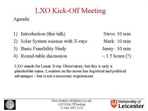
Meeting Agenda:

CMI Project Review: Project Name: MEMS Research: Materials Design and Processing for MMAs Number: P/059 Report Period 05/2004 -10/2004 1 Page 1 3

MEMS Research: Materials Design and Processing for MMAs Cambridge PI’s: Prof. Bill Milne, Prof. Norman Fleck, CU Engineering Dept. MIT PI: Prof. Duane Boning, EECS (replaces Prof. Spearing) Co-investigators: Flewitt, Moore, Seshia, Schmidt, Sutcliffe, Thompson, Wardle, Williams • Objective: To establish an intellectual community at Cambridge, focused on the development of Micro. Electro. Mechanical Systems (MEMS), introducing new materials, processes and design methods. • Intended Outcomes: Establishment of intellectual community at Cambridge, linked to MIT, built upon existing strengths at CUED. Generation of research results, and IP in areas of new materials, processes, material/process/sensor/actuator selection, actuator/sensor optimization, test methods for MEMS/MMA’s Page 2

Progress In Past Six Months (beyond technical) • Important activities, collaborations: – Collaborations • Mark Spearing has visited CUED several times during this period and has now moved to Southampton University • Carl Thompson has visited CUED during this period • Weekly MEMS meetings continuing at CUED and MIT • Discussions with Richard Syms I. C, Paul Kirby Cranfield, Julian Gardner Warwick University re interactions • Hayden Taylor (CU@MIT exchange ’ 02 -03) completed MEng at CU (’ 04) with D. Moore, has started Ph. D. at MIT in Fall ‘ 04 – Several papers published or in preparation with joint authorship between CUED and MIT – Web Site has been set up www-g. eng. cam. ac. uk/edm Page 4

Progress In Past 6 Months (technical) • • • Sutcliffe et al working on CMP. Luo, Flewitt, Milne and Chua have continued work on DLC MEMS growth, material development and device design and fabrication. Also the DLC work has been further extended by Luo et al to optimise the Ni/DLC bimorph actuated normally closed microgrippers- modified for Bio applications Flewitt and Moore worked on Micro-test system development. Tribological behaviour of MEMS materials by K S Faszer and John Williams. Chua, Milne et al investigated DLC for SAW devices. Fleck , Chua et al worked on microshear testing facility- new Flewitt and Ahsan worked on deployable locks based on a variety of material systems. Seshia continued work on MEMS devices specifically, micromechanical resonator oscillators for wireless transceiver and sensor applications, micromechanical biosensors, and inertial sensors Published guidelines/protocols for direct wafer bonding (K. Turner Ph. D. May ‘ 04) Boning continued work on DRIE wafer-level and pattern-dependent models Wardle joined effort and worked on piezoelectric vibrational energy harvesters- new Page 5

New Material Development - DLC Devices Luo, Milne, Flewitt, Spearing and Fleck Pages 14 & 15 • Creation of bimorph structures to create normally closed grippers • Combination of DLC and electrolytic Ni • Thermal actuation by resistance heating • Builds on earlier work on electro-deposition, DLC, micromechanical testing and modeling • Potential applications for bio-MEMS cell capture

Bio-compatible structure_1 DLC/Ni: 100/500 nm Polymer: 100 nm Stress: 6 GPa A thin polymer on a bimorph structure does not change the displacement of the device, but acts as a coating layer

Variable capacitor with DLC insulator Page 17 DLC as insulator (c) (e) (d) Cantilever type (f) Bridge type

Micro Piezoelectric Vibration Energy Harvester (MPVEH) Brian Wardle, MIT Aero/Astro • Objectives – Power for wireless sensor node applications such as infrastructure & structural health monitoring (SHM), RFID tags, homeland security, etc. – MEMS fabrication development – Low-level ambient sources targeted – Predictive design tools • Needs – Pervasive power from pervasive ambient sources – Wireless sensor’s power trending down, currently in 10 -100 s of W range – Voltage levels on order of Volts (3 V std. )

Other Items • Developments worth publicizing: Nano/MEMS M. Phil now up and running. • Modifications to statement of work and/or funding: essentially unchanged from original proposal. • Expected financial profile: near constant spend rate to end of project. All staff now in place.

Plans For Next Six Months • • Expected activities, collaborations: – Continued interchange of personnel, ideas – Increased interaction with industry as project thrusts yield results (wafer bonding/CMP, DRIE, materials selection) – Increased focus on devices in research • Integration of thermal grippers into practical devices - need to discuss further with Ted Acworth Expected milestones/deliverables: – Publish guidelines/protocols for DRIE (MIT) – Challenges and/or Issues To Address • • • Problem/Concern: – Continuation of MEMS activity beyond CMI funding (one year to go) Plan for resolution: – CU side actively looking for other funding sources for CU MEMS activities, some EU and EPSRC funding obtained, other sources sought – Funding for MEMS at CUED is continuing to increase How CMI can help – KIC -Tinytech? Page 22

Project 1/97 slides

CMI Project Review: Optical Properties of Nanoscale Arrays CMI-001 Fabricate Voltage-Tunable Photonic Devices Filled with Ferroelectrics P/097 May – Nov 2004

Optical Properties of Nanoscale Arrays Voltage-Tunable Photonic Devices Cambridge PI : Prof. James F. Scott, Earth Science Dept. MIT PI : Prof. Keith A Nelson, Chemistry Dept. • Brief Description of Project: Fabricate micron- or submicron-arrays of voltage-tunable ferroelectric devices consisting of two-dimensional patterns of high refractive index rods Characterize GHz-THz dielectric responses through "polaritonics" measurements w/ micron spatial resolution • Summary of Intended Outcomes: Delivery and test of a small number of prototype devices Prototype apparatus for GHz-THz dielectric metrology

Progress In Past Six Months • Important activities, collaborations: • Investigation of Pd-acetate based precursors for electroding • Continued collaboration with Finlay Morrison (Royal Soc. URF) • Continued discussions with Company X – exploratory pro bono experiments underway for microfluidics (ink-jet printers) • Contractual discussions with Company Y – drug delivery systems (monodisperse inhalers) • Contractual discussions with Company Z – venture capital company offering an initial £ 100, 000. • Fabrication of 10 -20 micron polaritonics structural elements • Direct imaging of polariton fields in 10 -20 micron structures • FDTD simulations of polariton propagation in small structures • Study of candidate materials for smaller polaritonics length scales • Basis of ~ 50 k. V/cm THz electric fields established

THz polaritonic bandgap materials fabricated in FE films by fs laser machining Can control THz polariton wave propagation, focusing Will reach 1 -5 m feature sizes • Milestones achieved: Polariton bandgap movie • Alternate electrode material (Ru) sourced : DER (2, 4 Dimethylpentadienyl)(ethylcyclopentadienal)ruthenium • Nanotubes fabricated using both Trento and KTH substrates • Deliverables completed: • Nanotube arrays from Trento and KTH substrates • Thin film polaritonics paper submitted for publication

Plans For Next Six Months • Expected activities, collaborations : • • Use of ruthenium for electroding (DER from Tosoh Corp) Receive delivery of Rapid Thermal Processor Continuation toward smaller length scales, higher THz fields Renewed attempt at THz polaritonics in FE nanotubes • Expected milestones: • • • Nanotubes with concentric electrode structure (Pd/SBT/Ru) Investigate electrical properties of single electroded nanotube Addressable array of electroded nanotubes 1 -5 micron polaritonics length scales 50 k. V/cm THz fields • Expected deliverables: • Fabrication of single electroded nanotube and evaluate piezoelectric response • Fabricate a small (4 x 4, 16 bit) array of addressable nanotubes • Publications on simulations & THz measurements in small structures

Other Items • Modifications to statement of work and/or funding: • Expected financial profile: • MIT is out of funds! • Anything else: • PDRA Dr Veronika Kugler successfully attained permanent post in UK industry (Carl Zeiss SMT Ltd) • JFS has given 5 invited talks in the last 6 months: MAGEL (La Rochelle, July), Eur. Physical Soc (Prague, Aug), Int. Conf. On Domains (Tsukuba, Aug), Eur. Conf on Appl of Polar Dielectrics (Liberec, Sept), NATO Adv Research Workshop (Lvov, Oct).

PR / Communications / Events • Any previous press interest in your project? By whom? What media? • Cambridge Univ. Research Services expects a press release by March or April. • Upcoming events, major publications, noteworthy dates in the next six months: • No publications on Cambridge work due to proprietary/patent reasons. • Publications on simulations & THz measurements in small structures • Do you need any help with your PR / communications / event planning?

Challenges And/or Issues To Address • Problem/Concern: • The deposition of Pd electrodes has turned out to be a complex materials science problem. Although Pd-acetate is a confirmed methodology (Steinhart, 2003), the processing does not normally produce an atomically flat, uniform sheet of metallic Pd as the electrode; rather, it yields crystals (see attached figures). Although these do conduct, in our judgment they are not suitable for commercial devices. Figure. Pd particles formed by thermal decomposition of a Pd-acetate thin film 1. 0 μm 0. 5 μm

Challenges And/or Issues To Address • Plan for resolution: • Ongoing investigation of incorporation of co-polymer (e. g. polyethylene glycol) to improve Pd microstructure • We have already taken delivery of a new Ru precursor chemical [Ruthenium-DER] from Tosoh (Tokyo) which has been shown in an unpublished Samsung-Tokyo collaboration to produce superior electrodes in DRAM trenches, compared with Pd. • How CMI can help: • This electroding problem has caused a 3 -month delay and associated unbudgeted costs.

Project 61 slides

Magnetoelectronic Devices Cambridge PI: Prof. J. Anthony C. Bland, Cavendish Lab. MIT PI: Prof. Caroline A. Ross, Materials Science and Engineering Department MIT Co-PI: Dr. Jagadeesh S. Moodera, Francis Bitter Magnet Laboratory Brief Description of Project: To develop the technology of magnetoelectronic devices. This will be achieved by work on two specific devices : an MRAM (magnetic random access memory) and a spin-diode. To select at least one of these devices for prototyping. To interact with potential manufacturers in the UK to bring a magnetoelectronic device to market.

MRAM prototypes based on Elliptical Ring cells F. J. Castaño, C. A. Ross Top: Made using evaporation: Co/Cu/Ni. Fe ring, Au/Ti metal Bottom: Made using sputtering: 20 nm Ni. Fe ring, Ta/Cu/Ta metal 2 um 500 nm 2 um

20 nm Ni. Fe/10 nm Fe. Mn rings of different widths: note exchange bias

Determination of vortex state circulation in a single ring during one applied field cycle O-V V-O T. J. Hayward, T. A. Moore, CU Hc 1 + Two major switching routes Hc 2 • Vortex state has same circulation (+ or -) on both downward and upward field sweeps + Focused Kerr microscopy V-O O-V Incident beam Ni. Fe ring dout = 5 m din = 3 m Sinusoidal field Observed transitions: O-V = onion-vortex, V-O = vortex-onion Hc 2 Hc 1 -

Design for a ring sensor element Applied field Bead GMR ring stack T. J. Hayward, J. Llandro Fixed layer: onion state Free layer: has vortex state at remanence • Bead absent: free layer oscillates between onion and remanent vortex state • Bead present: switching to onion state is suppressed • Measured as a change in the MR Resistance vs. current contact position External field distn: bead on nottop present of ring Ring d = 2 m Bead d = 2 m Max separation Mbead = 3 Hext Sensor • Signal amplitudes up to ~1 m. V

Spin-injection into Silicon by spin filtering using Eu. O allows efficient spin injection spin-injector spin-detector 2 nm Si spin diffusion channel 2 m x 10 m, SOI wafer, photolith. & RIE Ag or Y Eu. O Si Spin-injector, detector, contacts by e-beam lithography

Future possibilities for Tiny. Tech KIC A Tiny. Tech KIC could be focussed towards developing hybrid nanoscale devices - those incorporating electronic, magnetic and/or optical materials, allowing a range of new functionalities. The group might select several examples for collaborative development. Examples: Magnetoelectronic memory, or Sensor for biofunctionalized beads, based on magnetic rings; Spin transistor; Optically addressed ferromagnet/semiconductor memory element or processor; CNT-based transistor …

Project 38 slides

Carbon Nanotube Enabled Materials: CMI Program Summary, Nov. 2004 Synthesis Patterned arrays and vertically aligned CNT coatings Properties of directly spun CNT fibre Modeling Deformation Effects on Electrical Conductivity Equivalent Orthotropic Model of MWNT Properties of Vertically Aligned CNT Coatings Nanoindent and Nanoscratch Behavior Wetting Behavior Heat Transfer Behavior CNT Polymer Nanocomposites Stable suspension of SWCNTs Rheology of tube-filled melts and suspensions Mechanical behavior of thermoplastic composites M. C. Boyce, R. E. Cohen, J. Robertson, A. H. Windle, K. K. Gleason, G. Mc. Kinley, D. M. Parks M. Hamm, Q. Li, M. Motta, A. Pantano, M. Garg, K. Lau, C. He, B. J. Bico, V. Arnim, Kleinsorge, S Hofmann, K Teo, M Cantoro

Plasma Enhanced Chemical Vapour Deposition • • Large area, selective growth. Not bulk growth Ni catalyst. DC plasma C 2 H 2: NH 3 1: 3, 60 mbar pressure Bias voltage aligns CNTs (600 V) Selective growth. Nanotubes only grow where there is catalyst (Ni) NH 3 etches away unwanted a-C

Patterned Growth • Patterned catalyst gives selective growth • Shadow mask or • Lithography • Side view

Prior Work on CMI Project: Nanoindentation on Vertically Aligned Carbon Nanotube (VACNT) Forests Ø Produced by PECVD method Ø Dimensions can be better controlled Ø Applications: field emission devices, hydrophobic coatings, composite materials Typical indentation force-penetration curve from nanoindentation tests

Continuous wind up Feedstock Wind-up “Vertical” HOT ZONE Feedstock Wind-up “Horizontal” Ethanol* Thiophene Ferrocene 1100 to 1200 °C H 2 carrier gas

Multi wall CNTs: Microstructure of the fibre products 50 m Image analysis 1 m Fibre diameter of 20 to 50 m

Mechanical Properties The range of diameters along a fibre occurs due to differences in the local packing density of nanotubes and/or instabilities in the gasphase reaction. 1. 0 s 100 m t GPa 1 2 0 0 0 2 4 6 8 10 12 i Strain % 14 16 18 20

Nematic Dispersion 50 m Optical micrographs of carbon nanotube dispersions, imaged in reflected light with crossed polars. Song, W. Kinloch, I. A. and Windle, A. H. Science, 302, 1277 (2003)

– 1/2 Disclination Scanning electron micrograph showing details of orientation around a disclination of strength – 1/2.

New UK Collaborations arising: Synthesis and processing of CNT (i) “Canape” EU funded 8 M Euros Cambridge University + 14 partners in France, Germany, Belgium, Switzerland Italy (ii) DTI Consortium £ 3 M (Fibre process) Boeing Hexcel Thomas Swan Inst. of Occupational Medicine (iii) New Company “CUFLO” To bridge the University/industrial divide in UK (iv) Tiny. Tech KIC ?

The CMI Mission To enhance the competitiveness, productivity and entrepreneurship of the UK economy… By improving the effectiveness of knowledge exchange between university and industry, educating leaders, creating new ideas and developing programmes for change in universities, industry and government … Using an enduring partnership of Cambridge and MIT, and an extended network of participants.

CMI: Defining a space for knowledge exchange across research, education and industry Research Education KE Industry
 Kick off meeting agenda for construction project
 Low tech assistive technology definition
 Agenda sistemica y agenda institucional
 Rup sdlc
 Preseason coaches meeting agenda
 Background color
 Football meeting agenda
 Cft meeting in company
 Proposal kickoff meeting agenda
 Graduation meeting agenda
 Iep meeting agenda
 Close out meeting agenda
 Channel partner meeting agenda
 Architecture meeting agenda
 Circle k #45067
 Meeting agenda welcome and introductions
 Math department meeting agenda
 Iep meeting agenda
 The agenda communicates important information such as:
 Manifestation meeting for 504
 Troop committee meeting agenda
 Steering committee meeting agenda sample
 Pre construction meeting agenda example
 Architecture meeting agenda
 American legion meeting protocol
 Accounting meeting agenda
 Transition meeting agenda
 Uat kick off meeting presentation
 Coach parent meeting agenda
 Football coaches meeting agenda
 Parent meeting agenda for basketball
 Meeting agenda welcome and introductions
 Meeting agenda welcome and introductions
 Meeting agenda introduction
 Proposal kickoff meeting agenda
 Kanban replenishment meeting agenda
 Patty farris
 Hopkins baseball association
 Graduation meeting agenda
 Chs lancers
 Breakfast meeting agenda
 Technical meeting agenda
 Agenda for parents meeting
 Basketball coaches meeting agenda
