CLOUD TECHNOLOGY UNIT 3 Cloud Platforms Architecture Data


 • Resource Provisioning")


- Slides: 49
CLOUD TECHNOLOGY UNIT 3 Cloud Platforms Architecture
Data Center Design and Interconnection of networks
• A data center is often built with a large number of servers through a huge interconnection network. • In this section, we will study the design of largescale data centers and small modular data centers that can be housed in a 40 -ft truck container. • Then we will take a look at interconnection of modular data centers and their management issues and solutions.
Warehouse-Scale Data-Center Design
• Figure 4. 8 shows a data center that is as large as a shopping mall (11 times the size of a football field) under one roof. Such a data center can house 400, 000 to 1 million servers. • The data centers are built economics of scale— meaning lower unit cost for larger data centers. • A small data center could have 1, 000 servers. • The larger the data center, the lower the operational cost. The approximate monthly cost to operate a huge 400 -server data center is estimated by network cost $13/Mbps; storage cost $0. 4/GB; and administration costs. • These unit costs are greater than those of a 1, 000 server data center. The network cost to operate a small data center is about seven times greater and the storage cost is 5. 7 times greater. • Microsoft has about 100 data centers, large or small, which are distributed around the globe.
Data-Center Construction Requirements: • Most data centers are built with commercially available components. • An off-the-shelf server consists of a number of processor sockets, each with a multicore CPU and its internal cache hierarchy, local shared and coherent DRAM, and a number of directly attached disk drives. • The DRAM and disk resources within the rack are accessible through first-level rack switches and all resources in all racks are accessible via a cluster-level switch. • Consider a data center built with 2, 000 servers, each with 8 GB of DRAM and four 1 TB disk drives. • Each group of 40 servers is connected through a 1 Gbps link to a rack-level switch that has an additional eight 1 Gbps ports used for connecting the rack to the clusterlevel switch.
• Cooling System of a Data-Center Room
• Figure 4. 9 shows the layout and cooling facility of a warehouse in a data center. • The data-center room has raised floors for hiding cables, power lines, and cooling supplies. The cooling system is somewhat simpler than the power system. • The raised floor has a steel grid resting on stanchions about 2– 4 ft above the concrete floor. • The under-floor area is often used to route power cables to racks, but its primary use is to distribute cool air to the server rack. • The CRAC (computer room air conditioning) unit pressurizes the raised floor plenum by blowing cold air into the plenum.
Data-Center Interconnection Networks • A critical core design of a data center is the interconnection network among all servers in the datacenter cluster. • This network design must meet five special requirements: low latency, high bandwidth, low cost, message-passing interface (MPI) communication support, and fault tolerance. • The design of an inter-server network must satisfy both point-to-point and collective communication patterns among all server nodes. • Specific design considerations are given in the following sections.
Application Traffic Support • The network topology should support all MPI communication patterns. Both point-to-point and collective • MPI communications must be supported. • The network should have high bisection bandwidth to meet this requirement. • For example, one-to-many communications are used for supporting distributed file access.
Fault Tolerance and Graceful Degradation • The interconnection network should provide some mechanism to tolerate link or switch failures. • In addition, multiple paths should be established between any two server nodes in a data center. • Fault tolerance of servers is achieved by replicating data and computing among redundant servers. • Similar redundancy technology should apply to the network structure. • Both software and hardware network redundancy apply to cope with potential failures. • One the software side, the software layer should be aware of network failures. • Packet forwarding should avoid using broken links. • The network support software drivers should handle this transparently without affecting cloud operations.
Switch-centric Data-Center Design • There are two approaches to building data-center -scale networks: • One is switchcentric and the other is servercentric. • In a switch-centric network, the switches are used to connect the server nodes. The switchcentric design does not affect the server side. No modifications to the servers are needed. • The server-centric design does modify the operating system running on the servers. Special drivers are designed for relaying the traffic. Switches still have to be organized to achieve the connections.
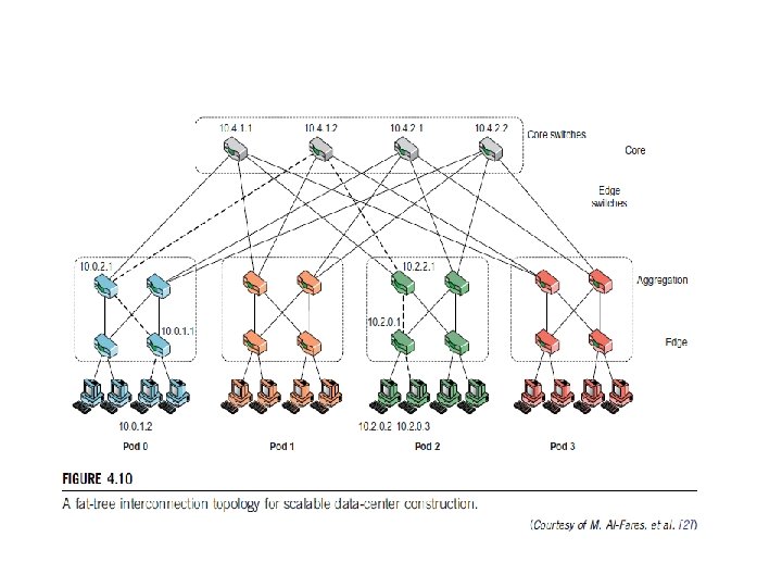
• Figure 4. 10 shows a fat-tree switch network design for data -center construction. The fat-tree topology is applied to interconnect the server nodes. • The topology is organized into two layers. Server nodes are in the bottom layer, and edge switches are used to connect the nodes in the bottom layer. • The upper layer aggregates the lower-layer edge switches. A group of aggregation switches, edge switches, and their leaf nodes form a pod. • Core switches provide paths among different pods. The fattree structure provides multiple paths between any two server nodes. • This provides fault-tolerant capability with an alternate path in case of some isolated link failures.
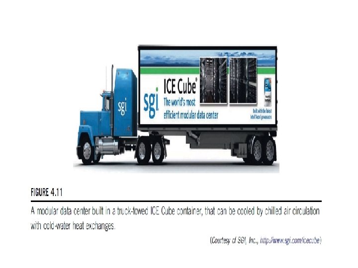
Modular Data Center in Shipping Containers • A modern data center is structured as a shipyard of server clusters housed in truck- towed containers. • Figure 4. 11 shows the housing of multiple sever racks in a truck-towed container in the SGI ICE Cube modular data center. • Inside the container, hundreds of blade servers are housed in racks surrounding the container walls. • An array of fans forces the heated air generated by the server racks to go through a heat exchanger, which cools the air for the next rack (detail in callout) on a continuous loop. • The SGI ICE Cube container can house 46, 080 processing cores or 30 PB of storage per container.
Container Data-Center Construction: • The data-center module is housed in a truck-towable container. • The modular container design includes the network, computer, storage, and cooling gear. One needs to increase cooling efficiency by varying the water and airflow with better air flow management. • Another concern is to meet seasonal load requirements. • The construction of a container-based data center may start with one system (server), then move to a rack system design, and finally to a container system. • This staged development may take different amounts of time and demand increasing costs. • Building a rack of 40 servers may take half a day. • Extending this to a whole container system with multiple racks for 1, 000 servers requires the layout of the floor space with power, networking, cooling, and complete testing.
Interconnection of Modular Data Centers: • Container-based data-center modules are meant for construction of even larger data centers using a farm of container modules. • Their interconnections are shown for building scalable data centers. • The following example is a server-centric design of the datacenter module.
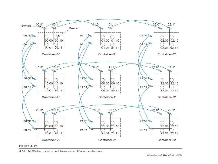
Inter-Module Connection Networks • The BCube is commonly used inside a server container. The containers are considered the building blocks for data centers. • Thus, despite the design of the inner container network, one needs another level of networking among multiple containers. • The proposed network was named MDCube (for Modularized Datacenter Cube). • This network connects multiple BCube containers by using high-speed switches in the BCube. Similarly, the MDCube is constructed by shuffling networks with multiple containers. • Figure 4. 13 shows how a 2 D MDCube is constructed from nine BCube 1 containers.
Data-Center Management Issues • Making common users happy The data center should be designed to provide quality service to the majority of users for at least 30 years. • Controlled information flow Information flow should be streamlined. Sustained services and high availability (HA) are the primary goals. • Multiuser manageability The system must be managed to support all functions of a data center, including traffic flow, database updating, and server maintenance. • Scalability to prepare for database growth The system should allow growth as workload increases. The storage, processing, I/O, power, and cooling subsystems should be scalable. • Reliability in virtualized infrastructure Failover, fault tolerance, and VM live migration should be integrated to enable recovery of critical applications from failures or disasters.
• Low cost to both users and providers The cost to users and providers of the cloud system built over the data centers should be reduced, including all operational costs. • Security enforcement and data protection Data privacy and security defense mechanisms must be deployed to protect the data center against network attacks and system interrupts and to maintain data integrity from user abuses or network attacks. • Green information technology Saving power consumption and upgrading energy efficiency are in high demand when designing and operating current and future data centers.
ARCHITECTURAL DESIGN OF COMPUTE AND STORAGE CLOUDS
A Generic Cloud Architecture Design • An Internet cloud is envisioned as a public cluster of servers provisioned on demand to perform collective web services or distributed applications using data-center resources. In this section, • We will discuss cloud design objectives and then present a basic cloud architecture design.
Cloud Platform Design Goals • Scalability, virtualization, efficiency, and reliability are four major design goals of a cloud computing platform. • Clouds support Web 2. 0 applications. Cloud management receives the user request, finds the correct resources, and then calls the provisioning services which invoke theresources in the cloud.
Enabling Technologies for Clouds
A Generic Cloud Architecture
Layered Cloud Architectural Development
Market-Oriented Cloud Architecture
• market-oriented resource management is necessary to regulate the supply and demand of cloud resources to achieve market equilibrium between supply and demand.
Quality of Service Factors • The data center comprises multiple computing servers that provide resources to meet service demands. • In the case of a cloud as a commercial offering to enable crucial business operations of companies, there are critical Qo. S parameters to consider in a service request, such as time, cost, reliability, and trust/security.
Virtualization Support and Disaster Recovery • • • Hardware Virtualization Support in Public Clouds Storage Virtualization for Green Data Centers Virtualization for Iaa. S VM Cloning for Disaster Recovery
Architectural Design Challenges • Challenge 1—Service Availability and Data Lock-in Problem • Challenge 2—Data Privacy and Security Concerns • Challenge 3—Unpredictable Performance and Bottlenecks • Challenge 4—Distributed Storage and Widespread Software Bugs • Challenge 5—Cloud Scalability, Interoperability, and Standardization • Challenge 6—Software Licensing and Reputation Sharing
INTER-CLOUD RESOURCE MANAGEMENT
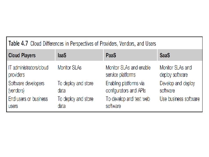
Extended Cloud Computing Services
• Cloud Service Tasks and Trends • Software Stack for Cloud Computing • Runtime Support Services
Resource Provisioning and Platform Deployment • Provisioning of Compute Resources (VMs) • Resource Provisioning Methods
• Demand-Driven Resource Provisioning
• Event-Driven Resource Provisioning
• Popularity-Driven Resource Provisioning
• Dynamic Resource Deployment
• Provisioning of Storage Resources
Virtual Machine Creation and Management
• • • Independent Service Management Running Third-Party Applications Virtual Machine Manager Virtual Machine Templates Distributed VM Management
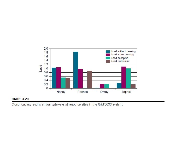
Example 4. 6 Experiments on an Inter. Grid Test Bed over the Grid’ 5000
Global Exchange of Cloud Resources