
CLOSE CONTROL UNIT By Olivier Lenglet RANGE DESCRIPTION
CLOSE CONTROL UNIT By Olivier Lenglet
RANGE DESCRIPTION 2
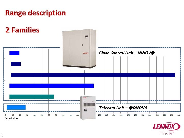
Range description 2 Families Close Control Unit – INNOV@ Telecom Unit – @DNOVA Capacity k. W 3
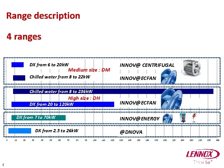
Range description 4 ranges DX from 6 to 20 k. W INNOV@ CENTRIFUGAL Chilled water from 8 to 22 k. W INNOV@ECFAN Medium size : DM Chilled water from 8 to 236 k. W High size : DH DX from 20 to 120 k. W DX from 7 to 70 k. W DX from 2. 5 to 26 k. W 4 INNOV@ECFAN INNOV@ENERGY @DNOVA
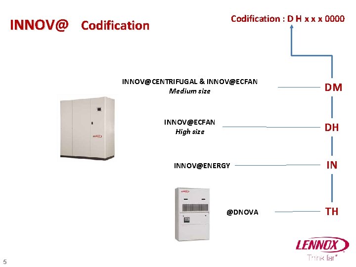
Codification : D H x x x 0000 INNOV@ Codification INNOV@CENTRIFUGAL & INNOV@ECFAN Medium size DM INNOV@ECFAN High size DH INNOV@ENERGY @DNOVA 5 IN TH
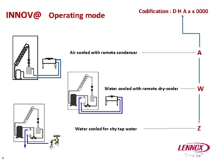
INNOV@ Operating mode Codification : D H A x x 0000 Air cooled with remote condenser Water cooled with remote dry-cooler Water cooled for city tap water 6 A W Z
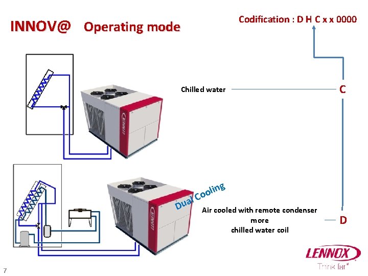
Codification : D H C x x 0000 INNOV@ Operating mode Chilled water C g in l o l Co Dua 7 Air cooled with remote condenser more chilled water coil D
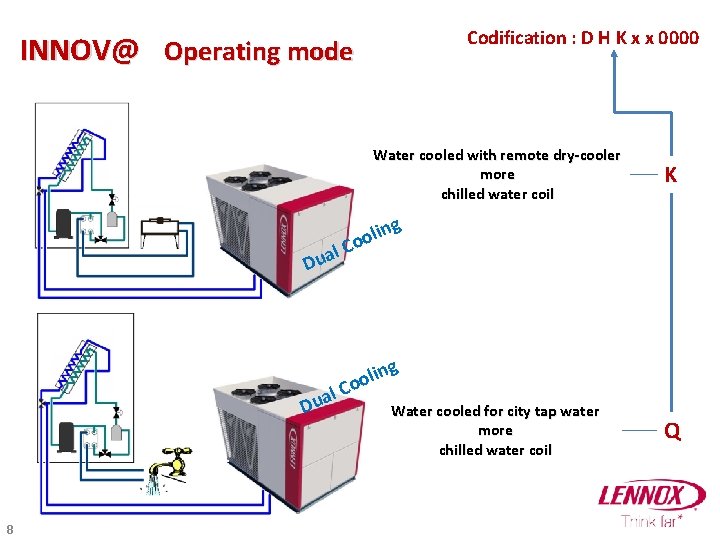
Codification : D H K x x 0000 INNOV@ Operating mode Water cooled with remote dry-cooler more chilled water coil K g n i l oo C l a Du g lin o o l. C Dua 8 Water cooled for city tap water more chilled water coil Q
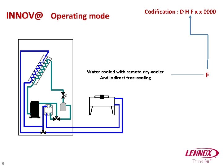
INNOV@ Operating mode Codification : D H F x x 0000 Water cooled with remote dry-cooler And indirect free-cooling 9 F
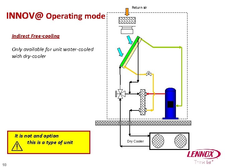
INNOV@ Operating mode Return air Indirect Free-cooling Only available for unit water-cooled with dry-cooler It is not and option this is a type of unit 10 Dry Cooler
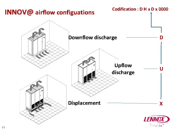
INNOV@ airflow configuations Codification : D H x D x 0000 Downflow discharge Upflow discharge Displacement 11 D U X
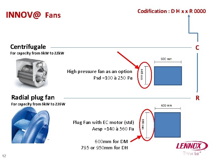
Codification : D H x x R 0000 INNOV@ Fans Centrifugale C For capacity from 6 k. W to 22 k. W High pressure fan as an option Psd =100 à 250 Pa Radial plug fan R For capacity from 6 k. W to 236 W Plug Fan with EC motor (std) Aesp =140 à 560 Pa 600 mm for DM 795 or 950 mm for DH 12
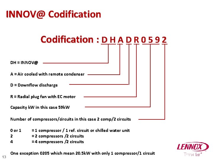
INNOV@ Codification : D H A D R 0 5 9 2 DH = INNOV@ A = Air cooled with remote condenser D = Downflow discharge R = Radial plug fan with EC motor Capacity k. W in this case 59 k. W Number of compressors/circuits in this case 2 comp/2 circuits 0 or 1 2 4 13 = 1 compressor / 1 ref. circuit or chilled water unit = 2 compressors /2 circuits = 4 compressors /2 circuits One exception 0205 which mean 20. 5 k. W with only 1 compressor/1 circuit
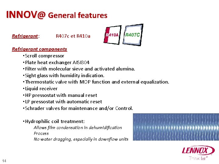
INNOV@ General features Refrigerant: R 407 c et R 410 a Refrigerant components • Scroll compressor • Plate heat exchanger AISI 304 • Filter with molecular sieve and activated alumina. • Sight glass with humidity indication. • Thermostatic valve with MOP function and external equalization. • Liquid receiver • HP pressostat with manual reset • LP pressostat with automatic reset • Schrader valves for maintenance and/or Control. • Hydrophilic coil treatment: Allows film condensation in dehumidification Process No water dragging, especially in downflow units 14
RANGE DESCRIPTION DM • 6 - 21 k. W direct expansion • 8 - 23 k. W chilled water 15
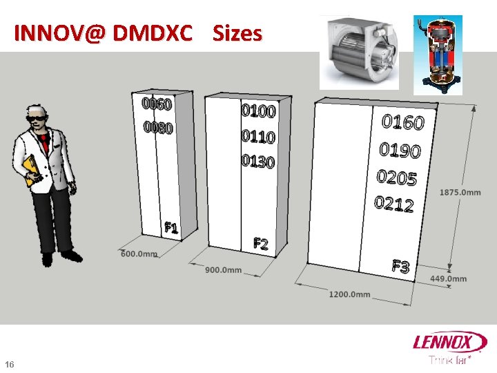
INNOV@ DMDXC Sizes 16
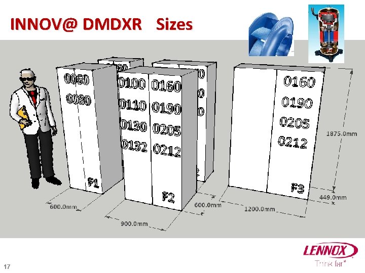
INNOV@ DMDXR Sizes 17
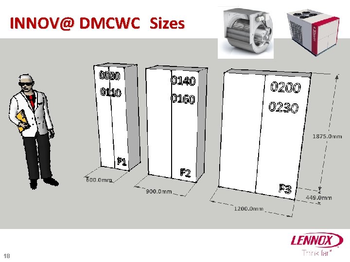
INNOV@ DMCWC Sizes 18
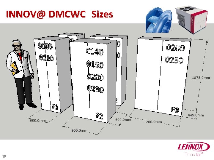
INNOV@ DMCWC Sizes 19
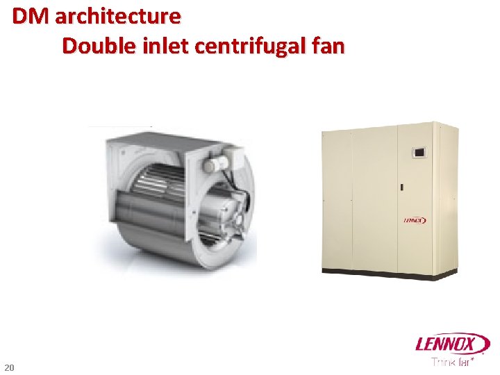
DM architecture Double inlet centrifugal fan 20
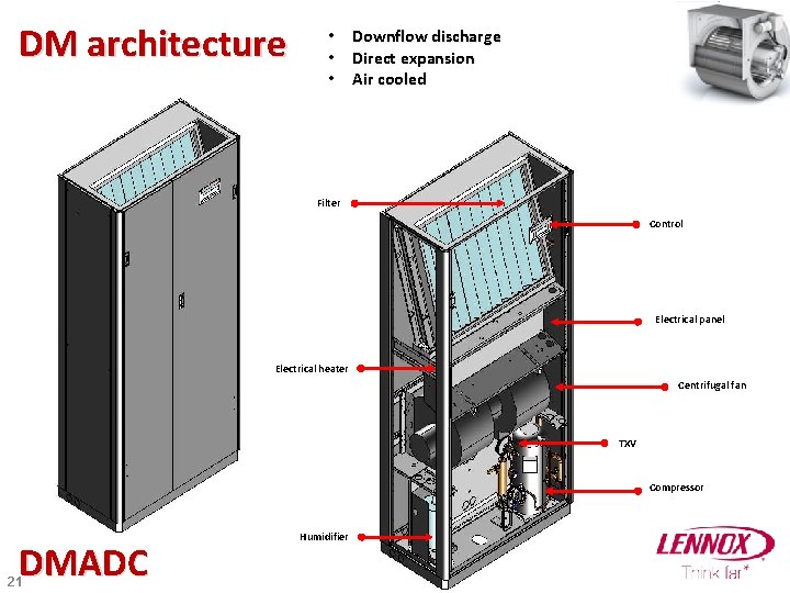
DM architecture • Downflow discharge • Direct expansion • Air cooled Filter Control Electrical panel Electrical heater Centrifugal fan TXV Compressor DMADC 21 Humidifier
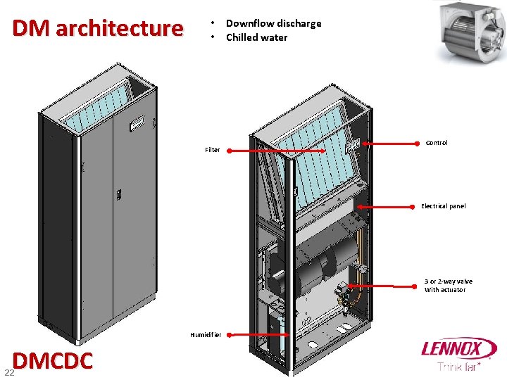
DM architecture • Downflow discharge • Chilled water Filter Control Electrical panel 3 or 2 -way valve With actuator Humidifier DMCDC 22
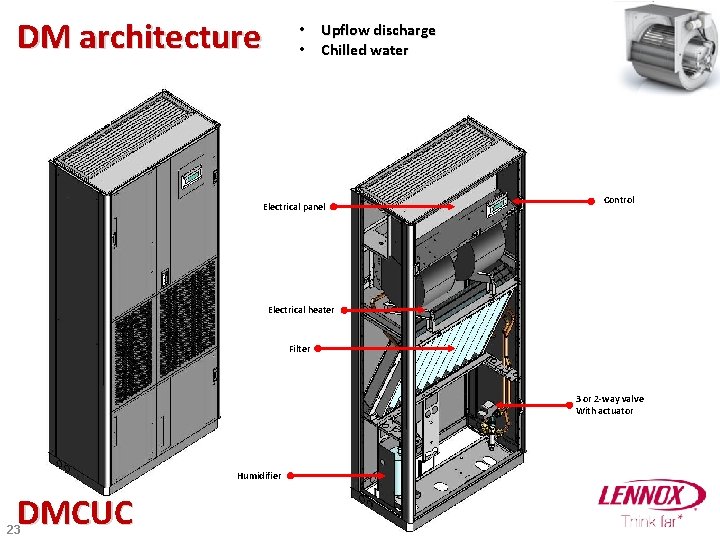
DM architecture • Upflow discharge • Chilled water Electrical panel Control Electrical heater Filter 3 or 2 -way valve With actuator Humidifier DMCUC 23
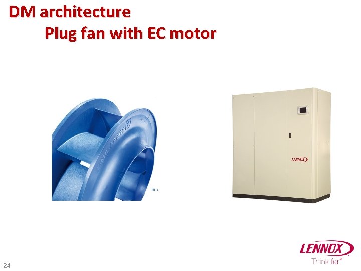
DM architecture Plug fan with EC motor 24
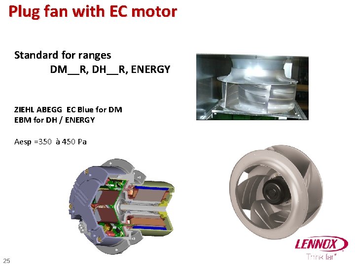
Plug fan with EC motor Standard for ranges DM__R, DH__R, ENERGY ZIEHL ABEGG EC Blue for DM EBM for DH / ENERGY Aesp =350 à 450 Pa 25
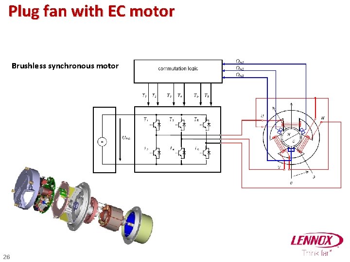
Plug fan with EC motor Brushless synchronous motor 26
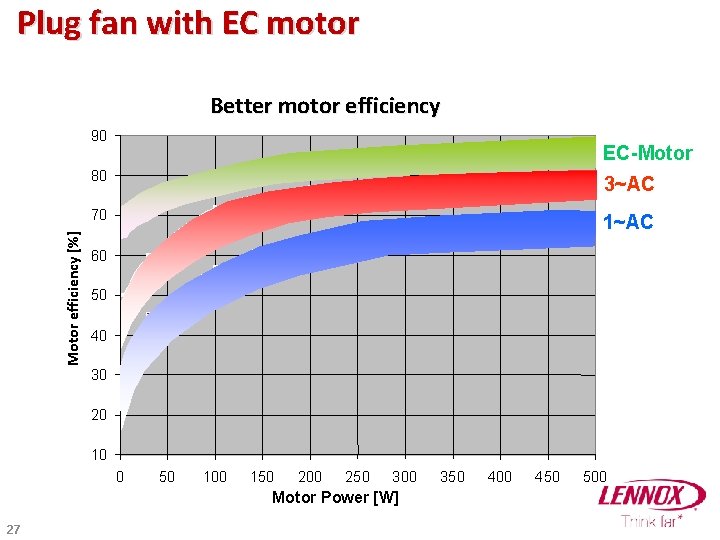
Plug fan with EC motor Better motor efficiency Motor efficiency [%] 90 EC-Motor 80 3~AC 70 1~AC 60 50 40 30 20 10 0 50 100 150 200 250 300 Motor Power [W] 27 350 400 450 500
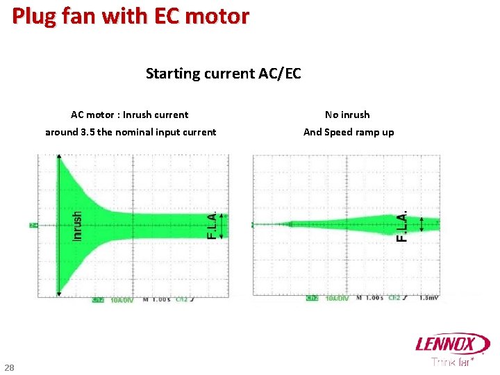
Plug fan with EC motor Starting current AC/EC 28 AC motor : Inrush current No inrush around 3. 5 the nominal input current And Speed ramp up
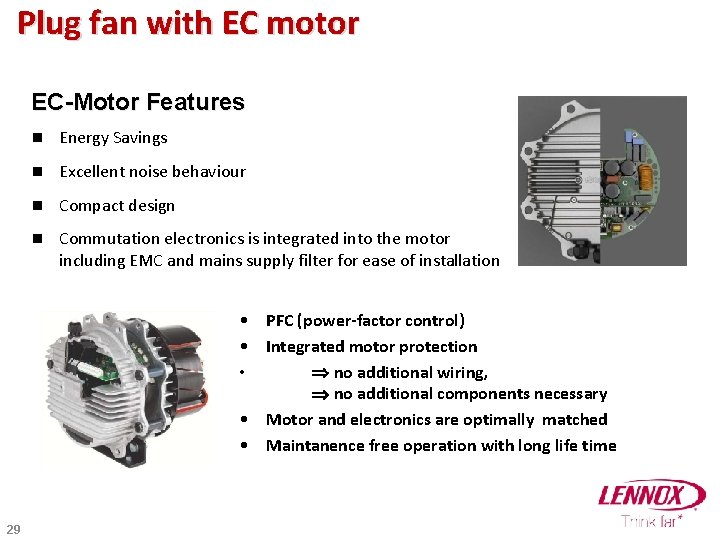
Plug fan with EC motor EC-Motor Features n Energy Savings n Excellent noise behaviour n Compact design n Commutation electronics is integrated into the motor including EMC and mains supply filter for ease of installation • PFC (power-factor control) • Integrated motor protection • no additional wiring, no additional components necessary • Motor and electronics are optimally matched • Maintanence free operation with long life time 29
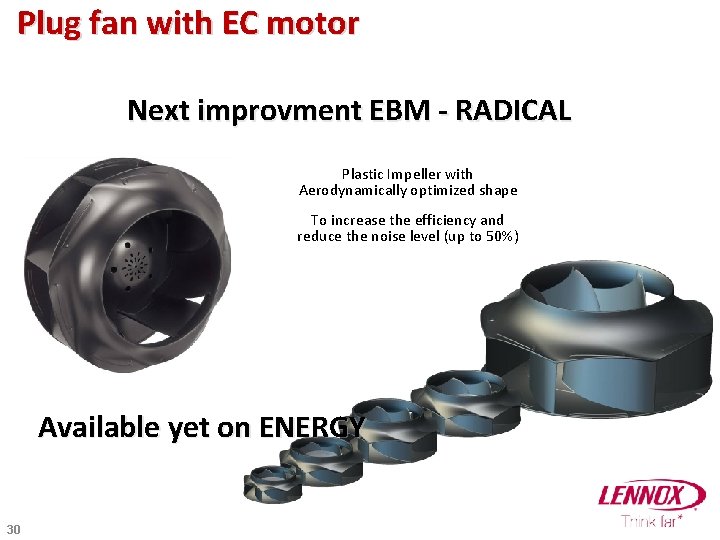
Plug fan with EC motor Next improvment EBM - RADICAL Plastic Impeller with Aerodynamically optimized shape To increase the efficiency and reduce the noise level (up to 50%) Available yet on ENERGY 30
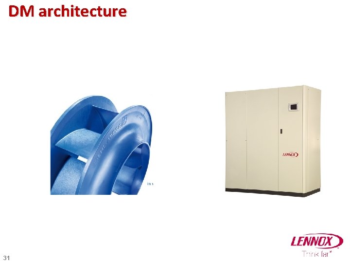
DM architecture 31
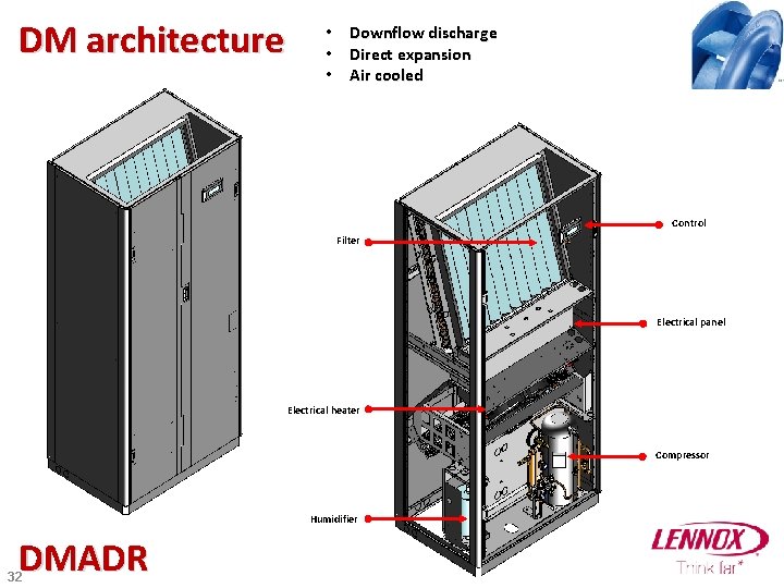
DM architecture • Downflow discharge • Direct expansion • Air cooled Control Filter Electrical panel Electrical heater Compressor Humidifier DMADR 32
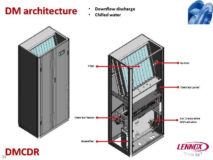
DM architecture • Downflow discharge • Chilled water Filter Control Electrical panel Electrical heater Humidifier DMCDR 33 3 or 2 -way valve With actuator
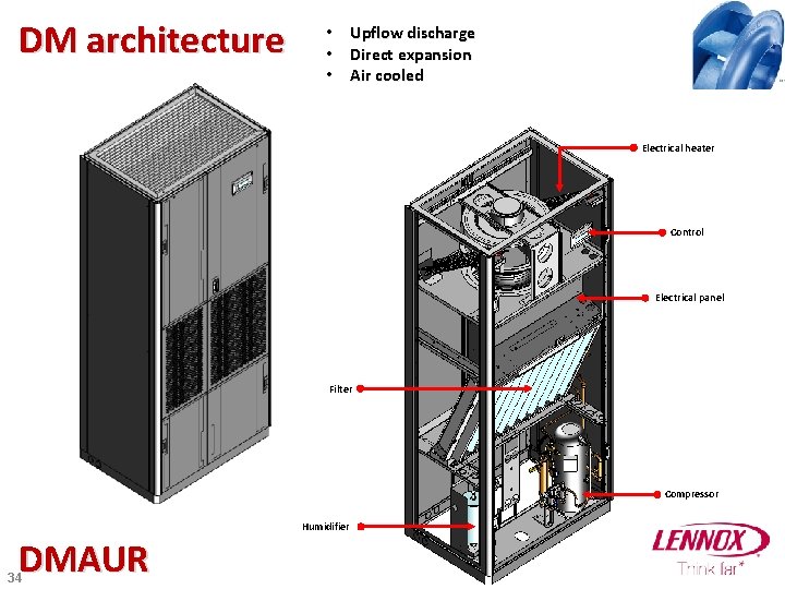
DM architecture • Upflow discharge • Direct expansion • Air cooled Electrical heater Control Electrical panel Filter Compressor Humidifier DMAUR 34
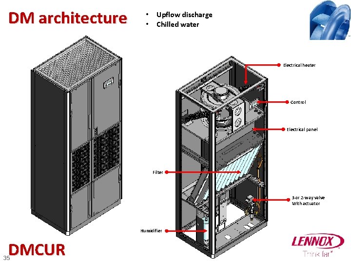
DM architecture • Upflow discharge • Chilled water Electrical heater Control Electrical panel Filter 3 or 2 -way valve With actuator Humidifier DMCUR 35
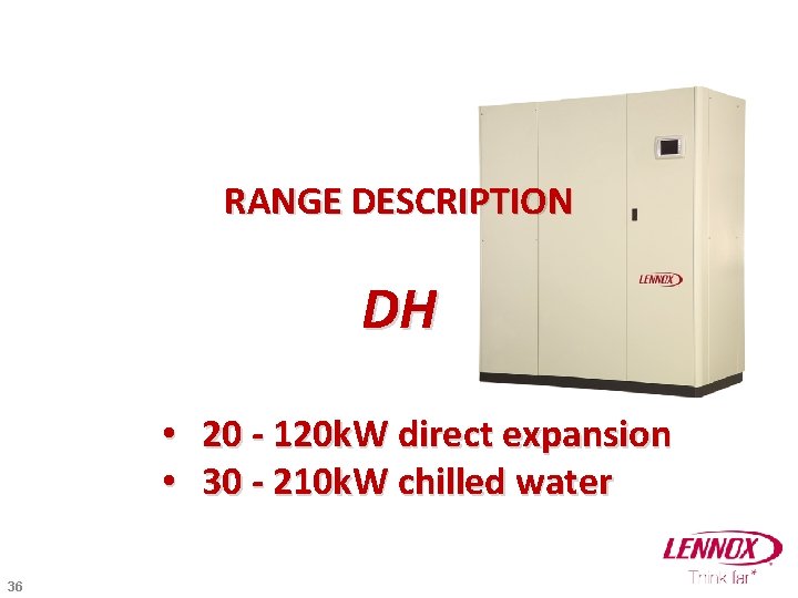
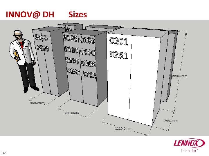
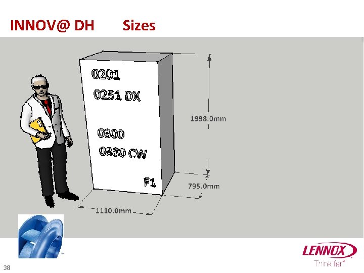
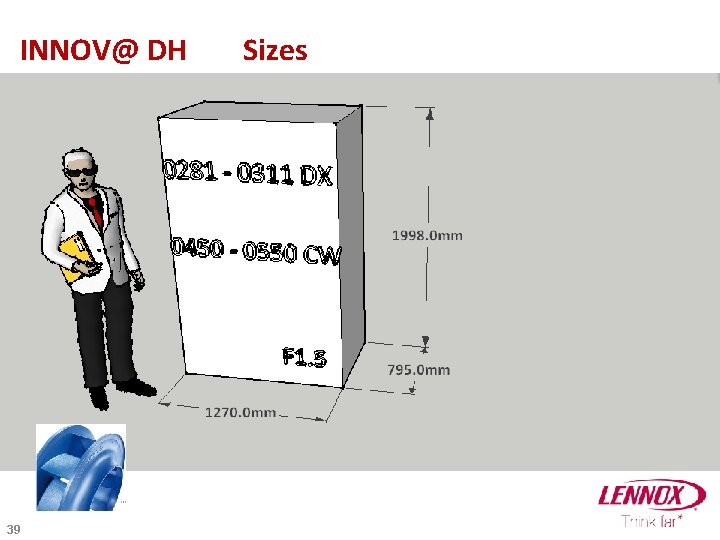
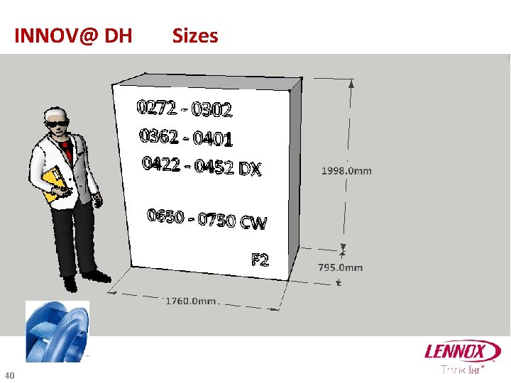
RANGE DESCRIPTION DH • 20 - 120 k. W direct expansion • 30 - 210 k. W chilled water 36
INNOV@ DH 37 Sizes
INNOV@ DH 38 Sizes
INNOV@ DH 39 Sizes
INNOV@ DH 40 Sizes
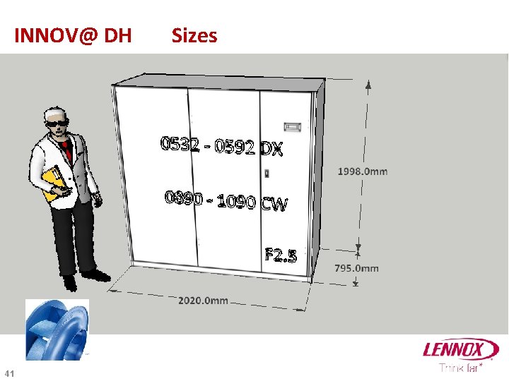
INNOV@ DH 41 Sizes
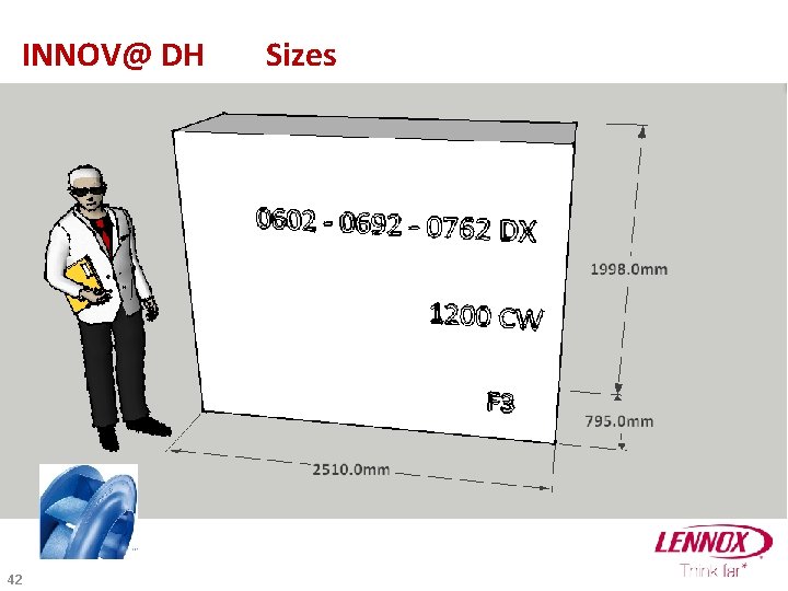
INNOV@ DH 42 Sizes
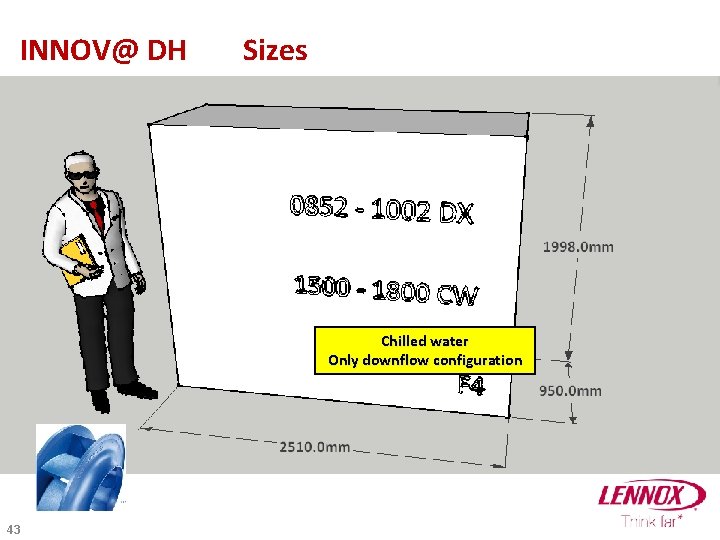
INNOV@ DH Sizes Chilled water Only downflow configuration 43
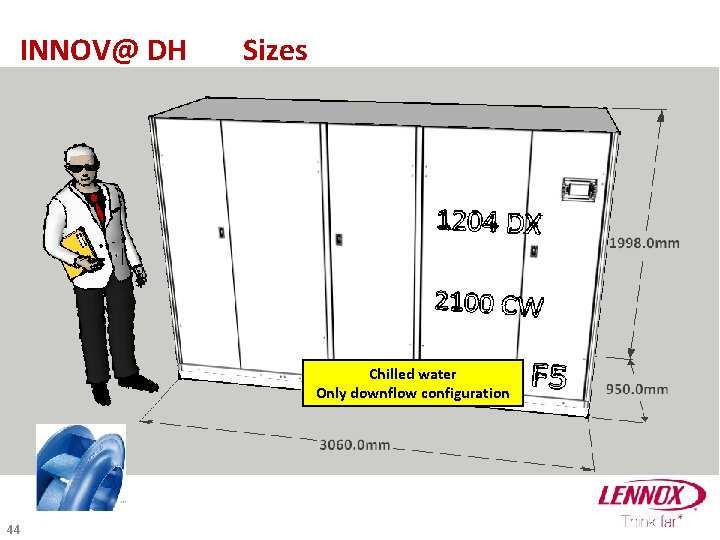
INNOV@ DH Sizes Chilled water Only downflow configuration 44
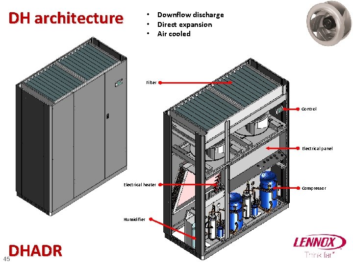
DH architecture • Downflow discharge • Direct expansion • Air cooled Filter Control Electrical panel Electrical heater Humidifier DHADR 45 Compressor
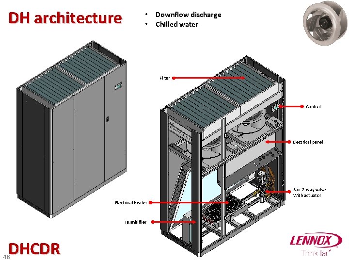
DH architecture • Downflow discharge • Chilled water Filter Control Electrical panel 3 or 2 -way valve With actuator Electrical heater Humidifier DHCDR 46
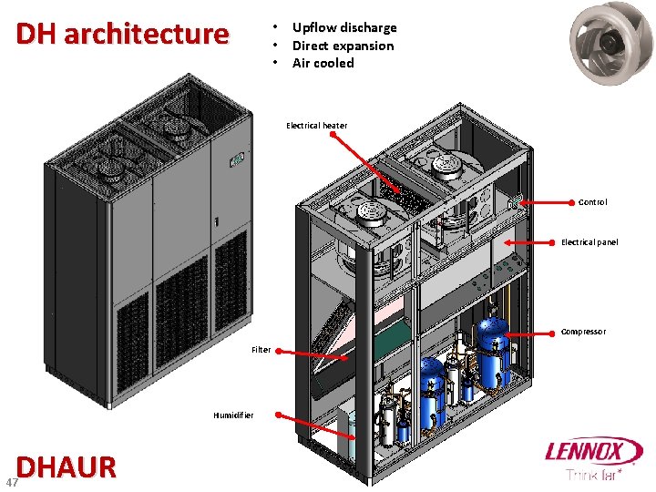
DH architecture • Upflow discharge • Direct expansion • Air cooled Radial fan Electrical heater Control Electrical panel Compressor Filter Humidifier DHAUR 47
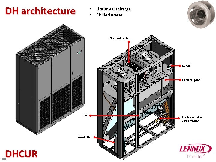
DH architecture • Upflow discharge • Chilled water Radial fan Electrical heater Control Electrical panel Filter Humidifier DHCUR 48 3 or 2 -way valve With actuator
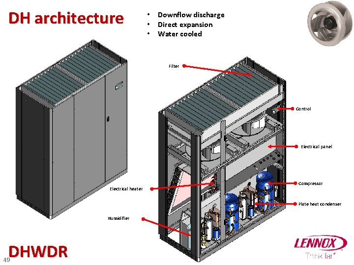
DH architecture • Downflow discharge • Direct expansion • Water cooled Filter Control Electrical panel Electrical heater Compressor Plate heat condenser Humidifier DHWDR 49
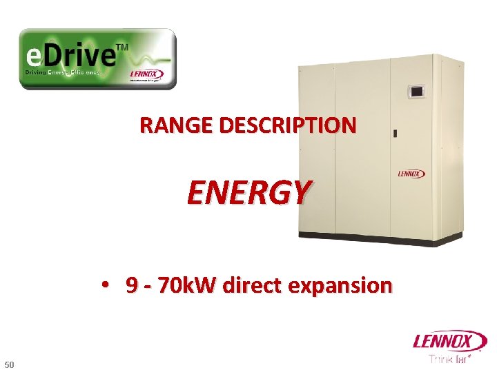
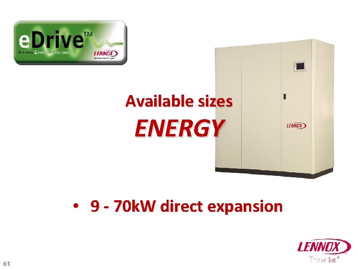
RANGE DESCRIPTION ENERGY • 9 - 70 k. W direct expansion 50
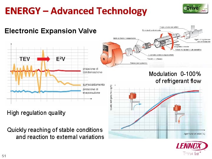
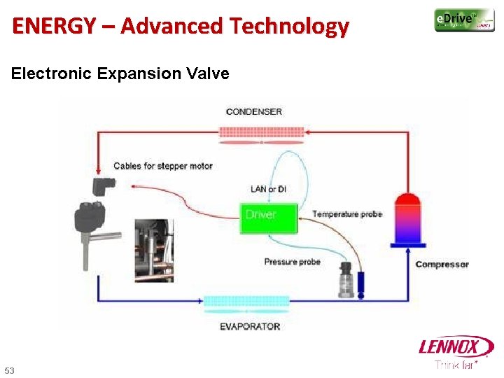
ENERGY – Advanced Technology Electronic Expansion Valve Modulation 0 -100% of refrigerant flow High regulation quality Quickly reaching of stable conditions and reaction to external variations 51
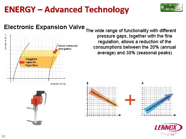
ENERGY – Advanced Technology Electronic Expansion Valve The wide range of functionality with different pressure gaps, together with the fine regulation, allows a reduction of the consumptions between the 20% (annual average) and 30% (seasonal peaks) 52
ENERGY – Advanced Technology Electronic Expansion Valve 53
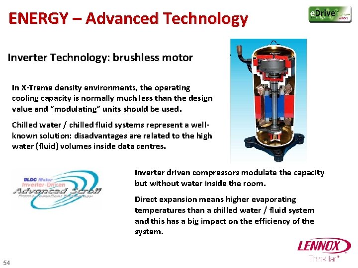
ENERGY – Advanced Technology Inverter Technology: brushless motor In X-Treme density environments, the operating cooling capacity is normally much less than the design value and “modulating” units should be used. Chilled water / chilled fluid systems represent a wellknown solution: disadvantages are related to the high water (fluid) volumes inside data centres. Inverter driven compressors modulate the capacity but without water inside the room. Direct expansion means higher evaporating temperatures than a chilled water / fluid system and this has a big impact on the efficiency of the system. 54
ENERGY – Advanced Technology Inverter Technology: brushless motor 1. Direct expansion + variable speed → better EER in partial load. 2. Compressor never stops → increasing in reliability 3. Stepless modulation → precise Temperature control 4. Quick reaction against heat load variation [ 6 Hz/second ] → no overheating in case of sharp heat load increasing. 5. Low speed in partial load → Lower noise level. ENERGY range fully integrate compressor management with air flow management, EEV management and remote condenser management 55
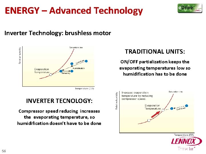
ENERGY – Advanced Technology Inverter Technology: brushless motor TRADITIONAL UNITS: ON/OFF partialization keeps the evaporating temperatures low so humidification has to be done INVERTER TECNOLOGY: Compressor speed reducing increases the evaporating temperature, so humidification doesn’t have to be done 56
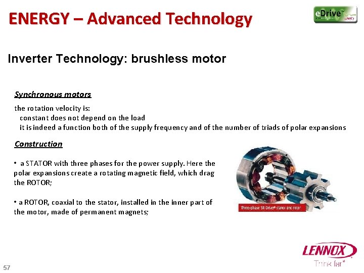
ENERGY – Advanced Technology Inverter Technology: brushless motor Synchronous motors the rotation velocity is: constant does not depend on the load it is indeed a function both of the supply frequency and of the number of triads of polar expansions Construction • a STATOR with three phases for the power supply. Here the polar expansions create a rotating magnetic field, which drag the ROTOR; • a ROTOR, coaxial to the stator, installed in the inner part of the motor, made of permanent magnets; 57
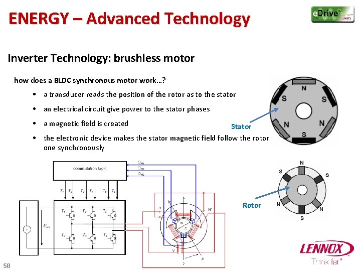
ENERGY – Advanced Technology Inverter Technology: brushless motor how does a BLDC synchronous motor work…? • a transducer reads the position of the rotor as to the stator • an electrical circuit give power to the stator phases • a magnetic field is created Stator • the electronic device makes the stator magnetic field follow the rotor one synchronously Rotor 58
ENERGY – Advanced Technology Inverter Technology: brushless motor PROS of the BLDC motor on the asynchronous motor: • • • 59 the rotor moves with the same velocity of the rotating magnetic field created by the power supply frequency, independently from the load Lower inertia of the motor (quicker acceleration/deceleration) Smaller dimension (lighter and cheaper components) lower noise emissions no start-up currents HIGHER ELECTRICAL EFFICIENCY thanks to: • no induction in the rotor because of permanent magnets in the rotor • no current losses in the rotor
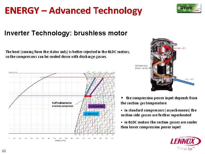
ENERGY – Advanced Technology Inverter Technology: brushless motor The heat (coming form the stator only) is better rejected in the BLDC motors, so the compressors can be cooled down with discharge gasses. • the compression power input depends from the suction gas temperature • in standard compressors (asynchronous) the suction side gasses are further superheated • in BLDC motors the suction gasses are cooler then lower compression power input 60
Available sizes ENERGY • 9 - 70 k. W direct expansion 61
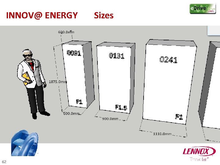
INNOV@ ENERGY 62 Sizes
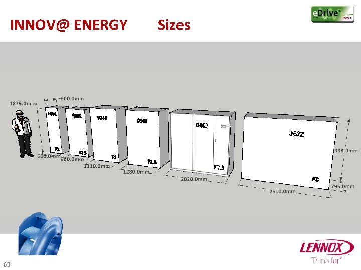
INNOV@ ENERGY 63 Sizes
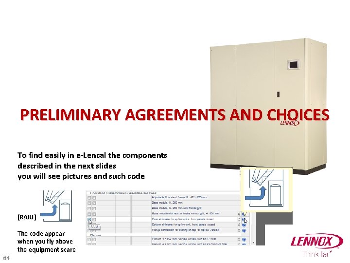
PRELIMINARY AGREEMENTS AND CHOICES To find easily in e-Lencal the components described in the next slides you will see pictures and such code (RAIU) The code appear when you fly above the equipment scare 64
PRELIMINARY CHOICES The whole INNOV@ range in DX system is now equipped with the advance control : p. CO 1 (CAREL) For the Chilled Water version it is already selected when you start a new selection nevertheless you can choose the pure slave version without controller I advise you to take always the clock card even if you don’t use time scheduling for maintenance and service it is interesting to have time in alarm report 65
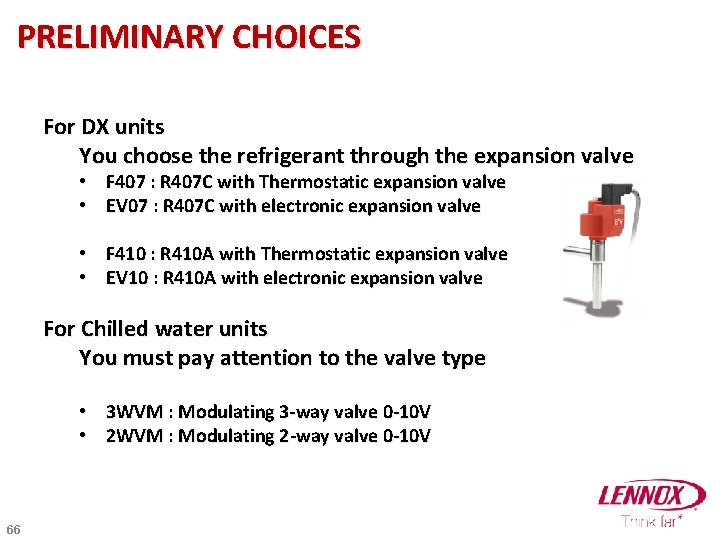
PRELIMINARY CHOICES For DX units You choose the refrigerant through the expansion valve • • F 407 : R 407 C with Thermostatic expansion valve EV 07 : R 407 C with electronic expansion valve • • F 410 : R 410 A with Thermostatic expansion valve EV 10 : R 410 A with electronic expansion valve For Chilled water units You must pay attention to the valve type • 3 WVM : Modulating 3 -way valve 0 -10 V • 2 WVM : Modulating 2 -way valve 0 -10 V 66
DESCRIPTION OF OPTIONS/ACCESSORIES 67
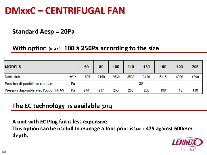
DMxx. C – CENTRIFUGAL FAN Standard Aesp = 20 Pa With option (HFAN) 100 à 250 Pa according to the size The EC technology is available (CFEC) A unit with EC Plug fan is less expensive This option can be usefull to manage a foot print issue : 475 against 600 mm depth. 68
HUMIDITY MANAGEMENT 69
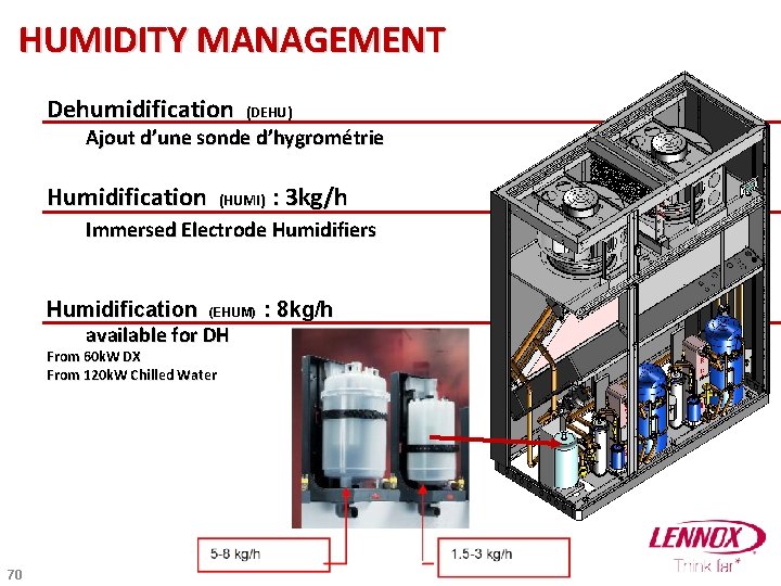
HUMIDITY MANAGEMENT Dehumidification (DEHU) Ajout d’une sonde d’hygrométrie Humidification (HUMI) : 3 kg/h Immersed Electrode Humidifiers Humidification (EHUM) : 8 kg/h available for DH From 60 k. W DX From 120 k. W Chilled Water 70
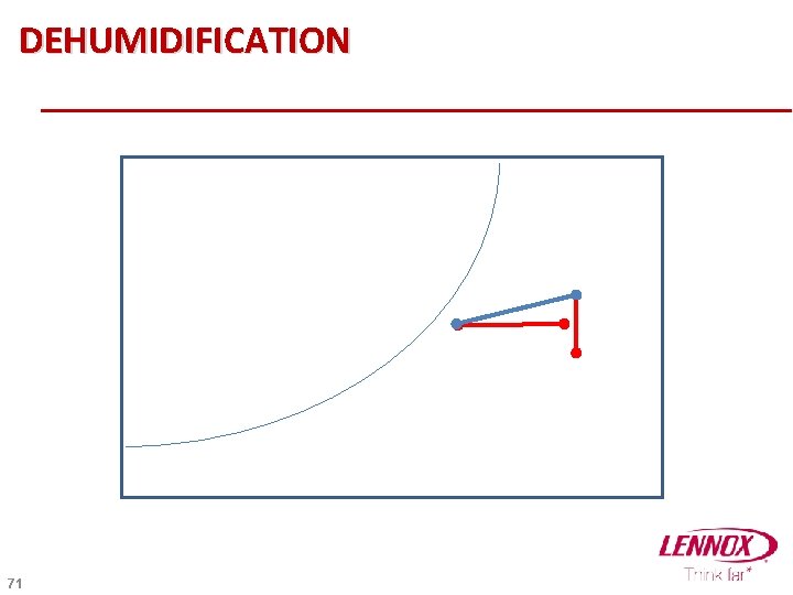
DEHUMIDIFICATION 71
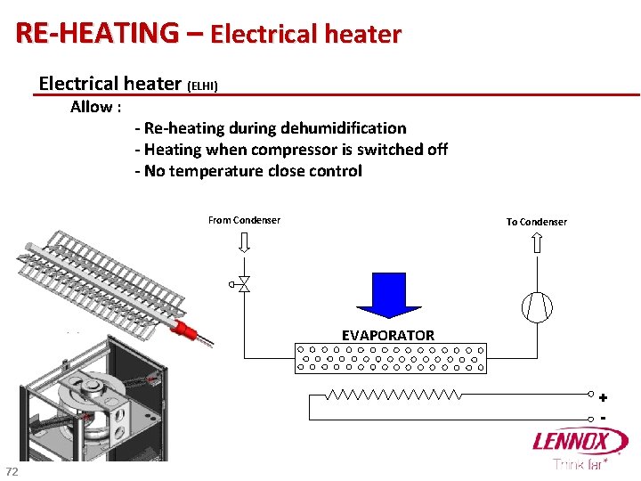
RE-HEATING – Electrical heater (ELHI) Allow : - Re-heating during dehumidification - Heating when compressor is switched off - No temperature close control From Condenser To Condenser EVAPORATOR + - 72
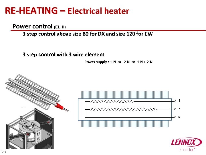
RE-HEATING – Electrical heater Power control (ELHI) 3 step control above size 80 for DX and size 120 for CW 3 step control with 3 wire element Power supply : 1 -N or 2 -N or 1 -N + 2 -N 1 2 N 73
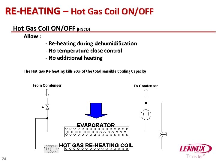
RE-HEATING – Hot Gas Coil ON/OFF (HGCO) Allow : - Re-heating during dehumidification - No temperature close control - No additional heating The Hot Gas Re-heating kills 90% of the total sensible Cooling Capacity From Condenser To Condenser EVAPORATOR HOT GAS RE-HEATING COIL 74
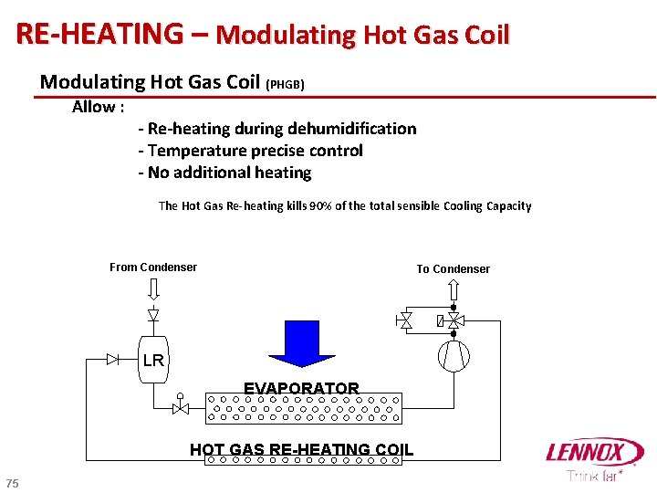
RE-HEATING – Modulating Hot Gas Coil (PHGB) Allow : - Re-heating during dehumidification - Temperature precise control - No additional heating The Hot Gas Re-heating kills 90% of the total sensible Cooling Capacity From Condenser To Condenser LR EVAPORATOR HOT GAS RE-HEATING COIL 75
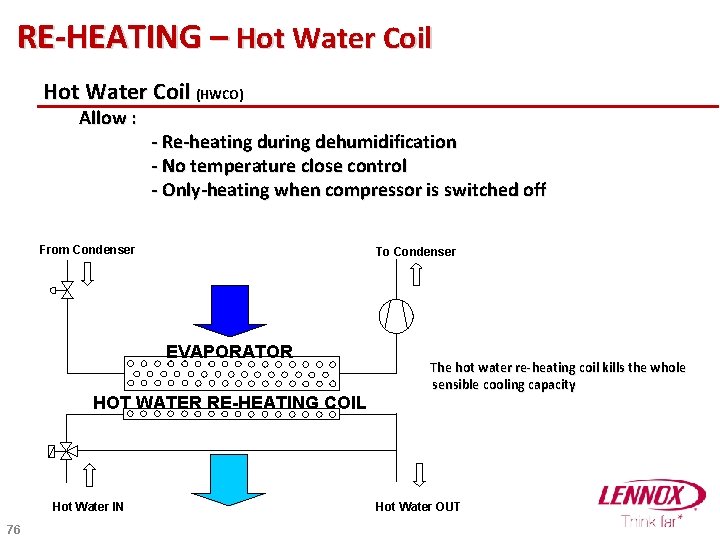
RE-HEATING – Hot Water Coil (HWCO) Allow : - Re-heating during dehumidification - No temperature close control - Only-heating when compressor is switched off From Condenser To Condenser EVAPORATOR HOT WATER RE-HEATING COIL Hot Water IN 76 The hot water re-heating coil kills the whole sensible cooling capacity Hot Water OUT
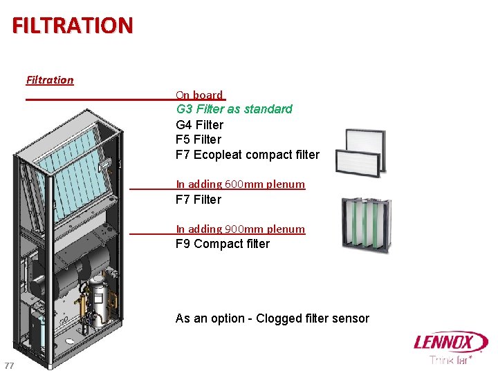
FILTRATION Filtration On board G 3 Filter as standard G 4 Filter F 5 Filter F 7 Ecopleat compact filter In adding 600 mm plenum F 7 Filter In adding 900 mm plenum F 9 Compact filter As an option - Clogged filter sensor 77
CONDENSING PRESSURE CONTROL 78
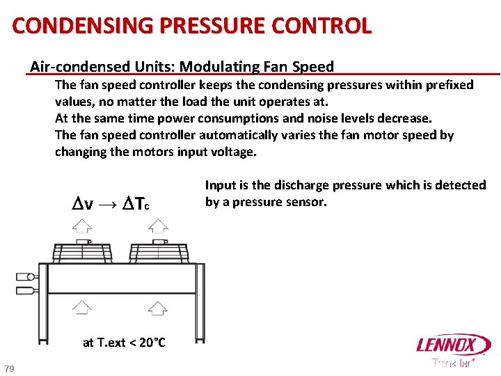
CONDENSING PRESSURE CONTROL Air-condensed Units: Modulating Fan Speed The fan speed controller keeps the condensing pressures within prefixed values, no matter the load the unit operates at. At the same time power consumptions and noise levels decrease. The fan speed controller automatically varies the fan motor speed by changing the motors input voltage. Dv → DTc at T. ext < 20°C 79 Input is the discharge pressure which is detected by a pressure sensor.
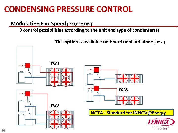
CONDENSING PRESSURE CONTROL Modulating Fan Speed (FSC 1, FSC 2, FSC 3) 3 control possibilities according to the unit and type of condenser(s) This option is available on-board or stand-alone (CCSxx) FSC 1 FSC 3 FSC 2 NOTA : Standard for INNOV@Energy 80
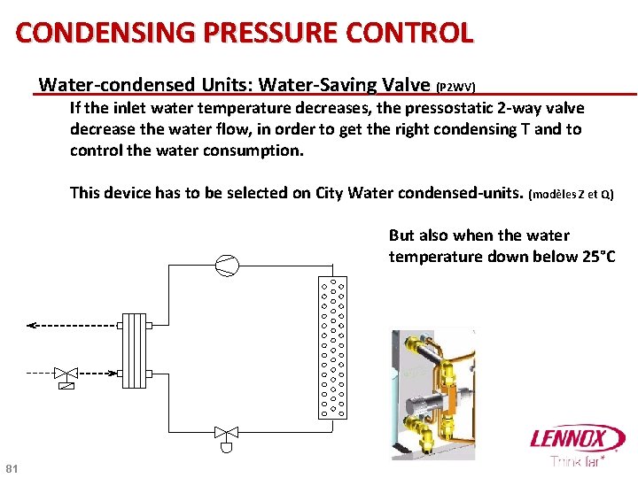
CONDENSING PRESSURE CONTROL Water-condensed Units: Water-Saving Valve (P 2 WV) If the inlet water temperature decreases, the pressostatic 2 -way valve decrease the water flow, in order to get the right condensing T and to control the water consumption. This device has to be selected on City Water condensed-units. (modèles Z et Q) But also when the water temperature down below 25°C 81
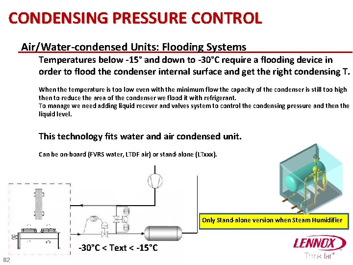
CONDENSING PRESSURE CONTROL Air/Water-condensed Units: Flooding Systems Temperatures below -15° and down to -30°C require a flooding device in order to flood the condenser internal surface and get the right condensing T. When the temperature is too low even with the minimum flow the capacity of the condenser is still too high then to reduce the area of the condenser we flood it with refrigerant. To manage we need adding liquid recever and valves system to control the condensing pressure and then the liquid level. This technology fits water and air condensed unit. Can be on-board (FVRS water, LTDF air) or stand-alone (LTxxx). Only Stand-alone version when Steam Humidifier -30°C < Text < -15°C 82
ACCESSORIES 83
ACCESSORIES Alarms Water leakage detector (WLD 1) Recommanded for chilled water version and unit with water coil Smoke detector (SDO 1) Detection of smoke particles by optical sensor. Fire detector (FDO 1) Thermostat in the return air. 84
ACCESSORIES Condensate pump Standard pump (COPU) Advise for chilled water and unit with hot water coil. High temperature pump (CPHT) Mandatory for unit with steam humidifier. Water coming from humidifier around 100°C. 85
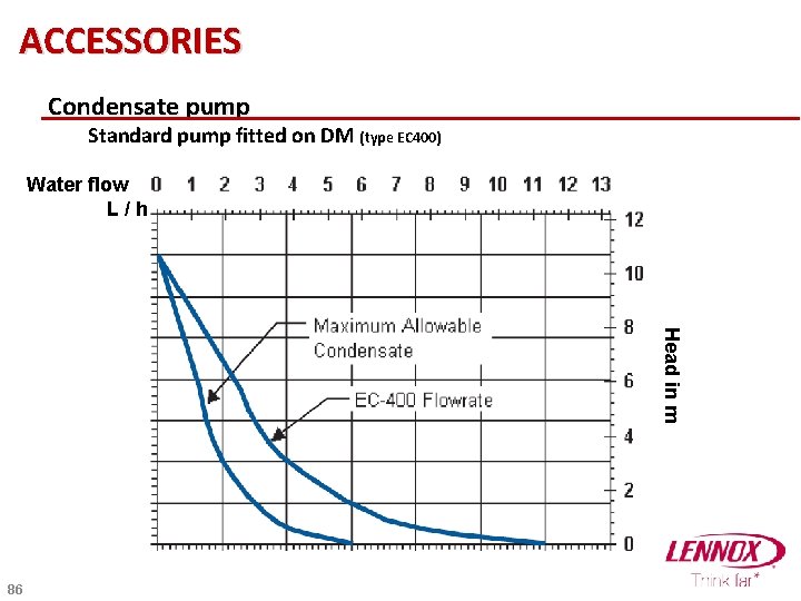
ACCESSORIES Condensate pump Standard pump fitted on DM (type EC 400) Water flow L/h Head in m 86
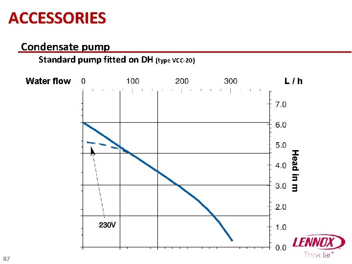
ACCESSORIES Condensate pump Standard pump fitted on DH (type VCC-20) Water flow L/h Head in m 87
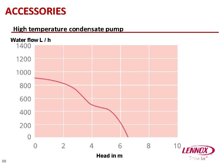
ACCESSORIES High temperature condensate pump Water flow L / h Head in m 88
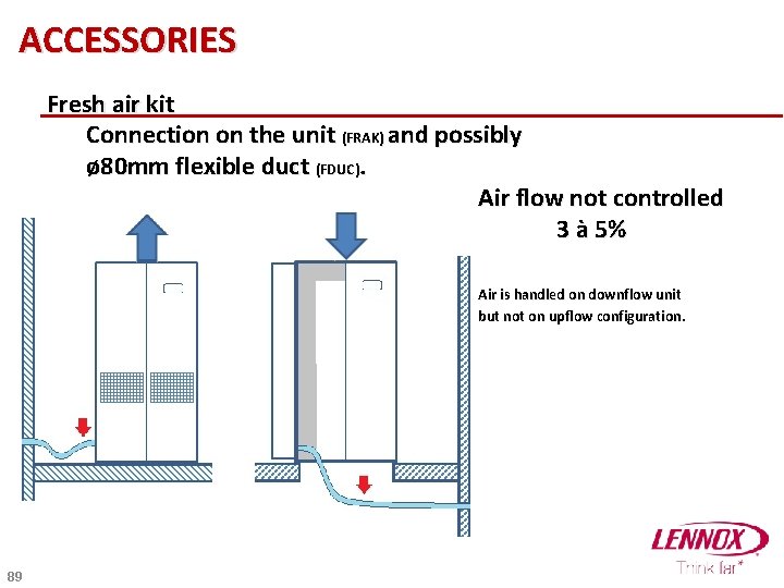
ACCESSORIES Fresh air kit Connection on the unit (FRAK) and possibly ø 80 mm flexible duct (FDUC). Air flow not controlled 3 à 5% Air is handled on downflow unit but not on upflow configuration. 89
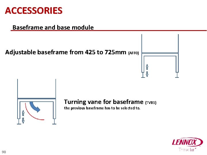
ACCESSORIES Baseframe and base module Adjustable baseframe from 425 to 725 mm (AFF 0) Turning vane for baseframe (TVB 1) the previous baseframe has to be selected to. 90
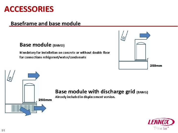
ACCESSORIES Baseframe and base module Base module (BAMO) Mandatory for installation on concrete or without double floor for connections refrigerant/water/condensate Base module with discharge grid (BAMG) Already included in displacement version. 91
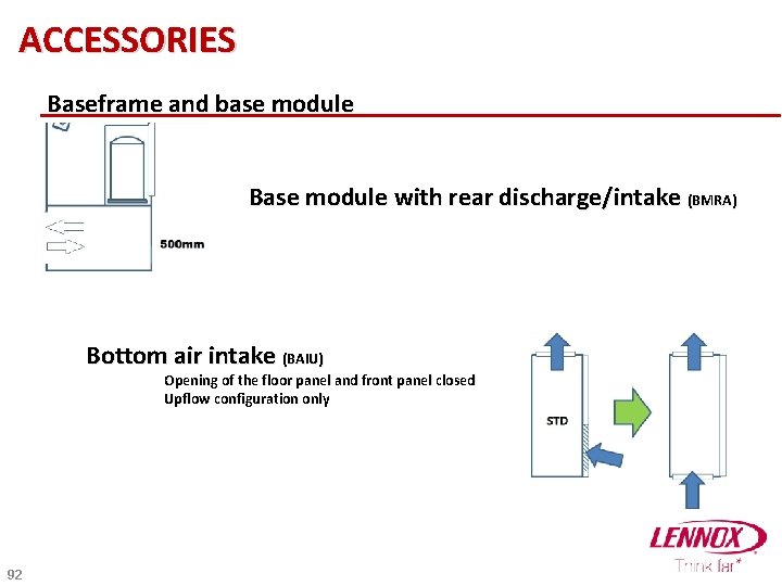
ACCESSORIES Baseframe and base module Base module with rear discharge/intake (BMRA) Bottom air intake (BAIU) Opening of the floor panel and front panel closed Upflow configuration only 92
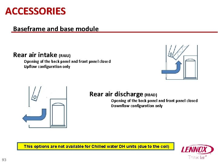
ACCESSORIES Baseframe and base module Rear air intake (RAIU) Opening of the back panel and front panel closed Upflow configuration only Rear air discharge (RBAD) Opening of the back panel and front panel closed Downflow configuration only This options are not available for Chilled water DH units (due to the coil) 93
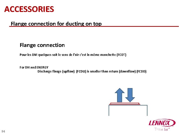
ACCESSORIES Flange connection for ducting on top Flange connection Pour les DM quelques soit le sens de l’air c’est la même manchette (FCDT) For DH and ENERGY Discharge flange (upflow) (FCDU) is smaller than return (downflow) (FCDD) 94
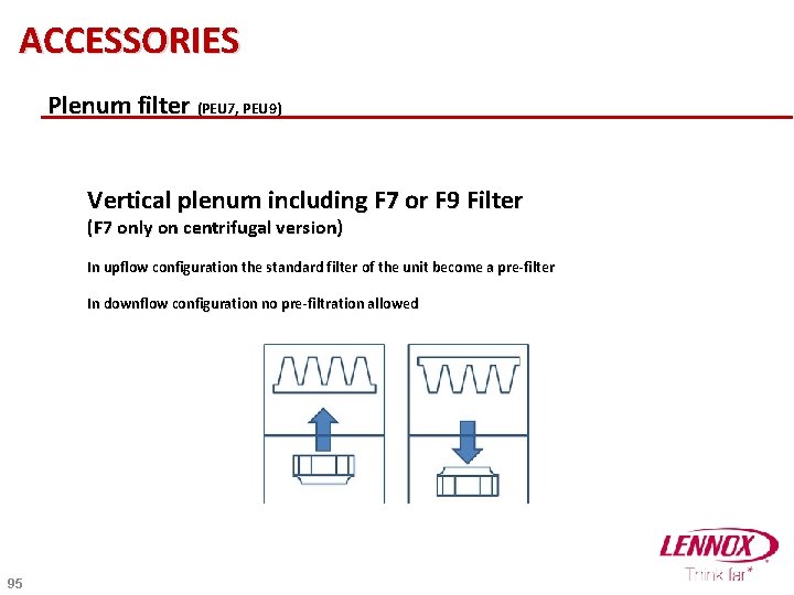
ACCESSORIES Plenum filter (PEU 7, PEU 9) Vertical plenum including F 7 or F 9 Filter (F 7 only on centrifugal version) In upflow configuration the standard filter of the unit become a pre-filter In downflow configuration no pre-filtration allowed 95
ACCESSORIES Empty plenum (PLV 5, PLV 6, PLV 9, PLV 1) Vertical plenum to complete the unit till the ceiling Same shape and color than the unit For DM are available 600, 900, 1200 mm For DH and ENERGY are available 500, 600, 900, 1200 mm 96
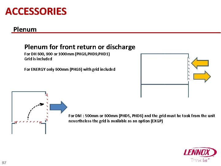
ACCESSORIES Plenum for front return or discharge For DH 600, 900 or 1000 mm (PHG 6, PHD 9, PHD 1) Grid is included For ENERGY only 600 mm (PHG 6) with grid included For DM : 500 mm or 600 mm (PHD 5, PHD 6) and the grid must be took from the unit nevertheless the grid is available as an option (EXGP) 97
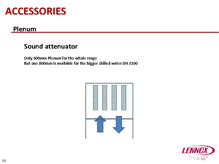
ACCESSORIES Plenum Sound attenuator Only 600 mm Plenum for the whole range But one 800 mm is available for the bigger chilled water DH 2100 98
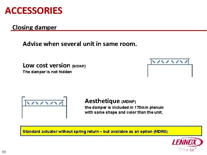
ACCESSORIES Closing damper Advise when several unit in same room. Low cost version (MDNP) The damper is not hidden Aesthetique (MDNP) the damper is included in 170 mm plenum with same shape and color than the unit. Standard actuator without spring return – but available as an option (MDR 0) 99
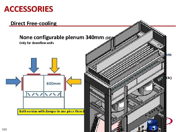
ACCESSORIES Direct Free-cooling None configurable plenum 340 mm (DFCP) Only for downflow units Configurable plenum 600 mm (DFCN) Only downflow unit Both version with damper in one piece then doesn’t allow full closing of the unit 100
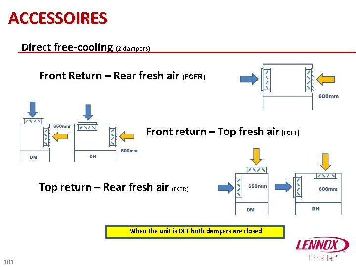
ACCESSOIRES Direct free-cooling (2 dampers) Front Return – Rear fresh air (FCFR) pas la fonction d’isolement Front return – Top fresh air (FCFT) Top return – Rear fresh air (FCTR) When the unit is OFF both dampers are closed 101
OPTION DESCRIPTION OF CONDENSER/DRY-COOLER 102
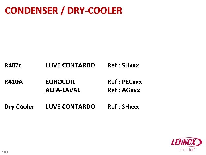
CONDENSER / DRY-COOLER R 407 c LUVE CONTARDO Ref : SHxxx R 410 A EUROCOIL ALFA-LAVAL Ref : PECxxx Ref : AGxxx Dry Cooler LUVE CONTARDO Ref : SHxxx 103
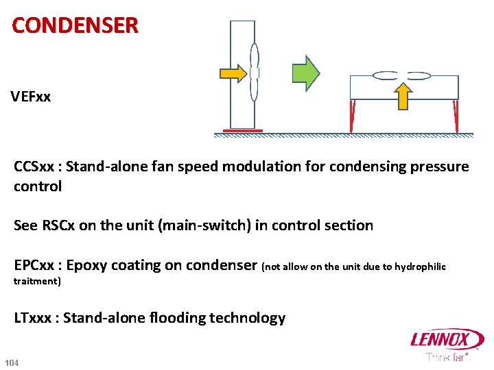
CONDENSER VEFxx CCSxx : Stand-alone fan speed modulation for condensing pressure control See RSCx on the unit (main-switch) in control section EPCxx : Epoxy coating on condenser (not allow on the unit due to hydrophilic traitment) LTxxx : Stand-alone flooding technology 104
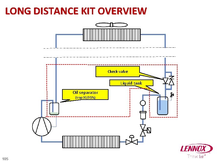
LONG DISTANCE KIT OVERVIEW Check-valve Liquid tank Oil separator (trap 90/95%) 105
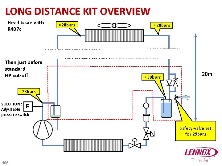
LONG DISTANCE KIT OVERVIEW Head issue with R 407 c Then just before standard HP cut-off ≈28 bars ≈30 bars 20 m 28 bars SOLUTION : P Adjustable pressure-switch Safety-valve set for 29 bars 106
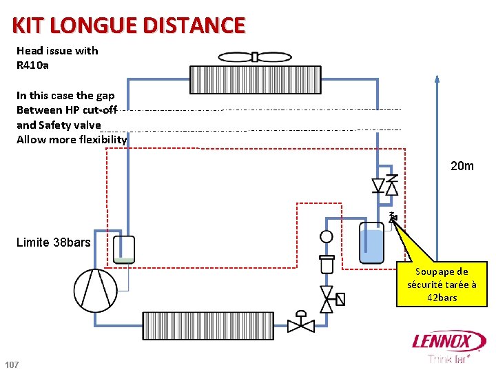
KIT LONGUE DISTANCE Head issue with R 410 a In this case the gap Between HP cut-off and Safety valve Allow more flexibility 20 m Limite 38 bars Soupape de sécurité tarée à 42 bars 107
END 108
- Slides: 108