Clearance in Sheet Metal Cutting Distance between punch

Clearance in Sheet Metal Cutting Distance between punch cutting edge and die cutting edge § Typical values range between 4% and 8% of stock thickness § If too small, fracture lines pass each other, causing double burnishing and larger force § If too large, metal is pinched between cutting edges and excessive burr results
 clearance too")
Clearance in Sheet Metal Cutting FIGURE 20. 5 Effect of clearance: (a) clearance too small causes less-than optimal fracture and excessive forces; and (b) clearance too large causes oversized burr. Symbols v and F indicate motion and applied force, respectively.

Clearance in Sheet Metal Cutting § Recommended clearance is calculated by: c = at where c = clearance; a = allowance; and t = stock thickness § Allowance a is determined according to type of metal

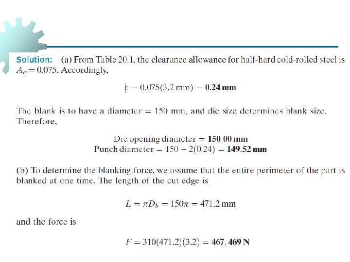
Sheet Metal Groups Allowances Metal group a 1100 S and 5052 S aluminum alloys, all tempers 0. 045 2024 ST and 6061 ST aluminum alloys; brass, soft cold rolled steel, soft stainless steel 0. 060 Cold rolled steel, half hard; stainless steel, half hard and full hard 0. 075

Punch and Die Sizes § For a round blank of diameter Db: § Blanking punch diameter = Db ‑ 2 c § Blanking die diameter = Db where c = clearance § For a round hole of diameter Dh: § Hole punch diameter = Dh § Hole diameter = Dh + 2 c where c = clearance

Punch and Die Sizes Figure 20. 6 Die size determines blank size Db; punch size determines hole size Dh. ; c = clearance

Angular Clearance Purpose: allows slug or blank to drop through die § Typical values: 0. 25 to 1. 5 on each side Figure 20. 7 Angular clearance.
 F=St. L where S = shear")
Cutting Forces Important for determining press size (tonnage) F=St. L where S = shear strength of metal; t = stock thickness, and L = length of cut edge

Example Around disk of 150 -mm diameter is to be blanked from a strip of 3. 2 -mm, half-hard cold-rolled steel whose shear strength = 310 MPa. Determine (a) the appropriate punch and die diameters, and (b) blanking force.
 Cutoff and (b) parting.")
Other sheet metal cutting Operation FIGURE 20. 8 (a) Cutoff and (b) parting.

Cutoff § Cutoff: is a shearing operation in which blanks are separated from a sheet-metal strip by cutting the opposite sides of the part in sequence, as shown in Figure 20. 8(a). With each cut, a new part is produced. The features of a cutoff operation that distinguish it from a conventional shearing operation are (1) the cut edges are not necessarily straight, and (2) the blanks can be nested on the strip in such a way that scrap is avoided.
 Slotting, (b) perforating, (c) notching and")
Slotting, Perforating and Notching FIGURE 20. 9 (a) Slotting, (b) perforating, (c) notching and seminotching. Symbol v indicates motion of strip
 Shaving and (b) fine blanking.")
Trimming, Shaving, and Fine Blanking FIGURE 20. 10 (a) Shaving and (b) fine blanking. Symbols: v = motion of punch, Fh = blank holding force.
- Slides: 16