Clawbot with Controller Program the VEX Controller to

Clawbot with Controller Program the VEX Controller to direct the Clawbot IQ through several engaging challenges using the concept of loops.

Discover new hands-on builds and programming opportunities to further your understanding of a subject matter.

The Completed Look of the Build The completed Clawbot IQ build. This robot is designed so that it can be built quickly and drive around either autonomously or with the Controller in a short amount of time.

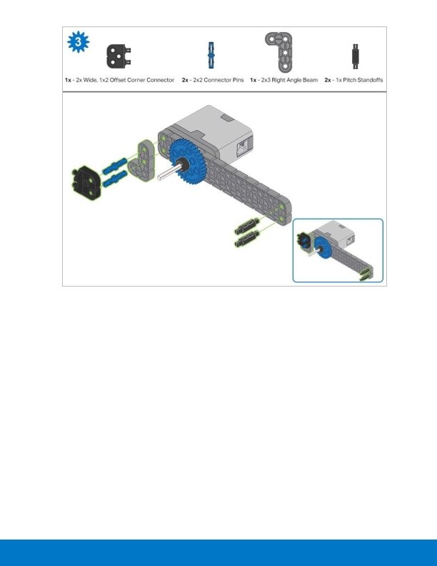
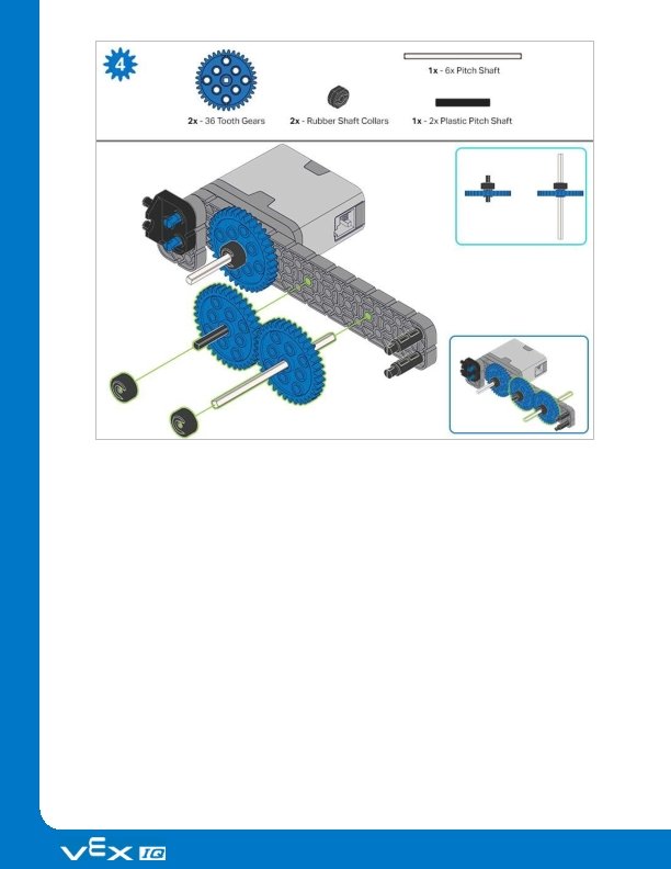
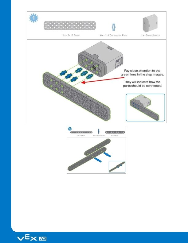
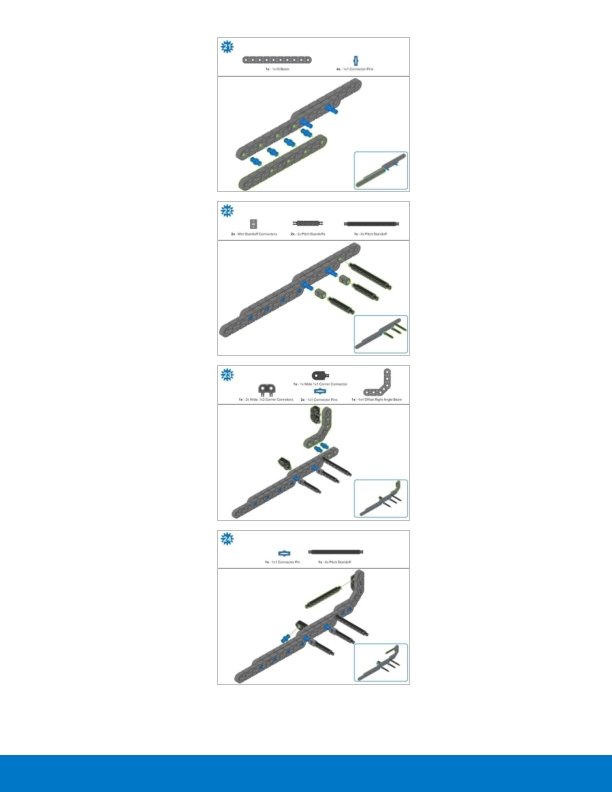
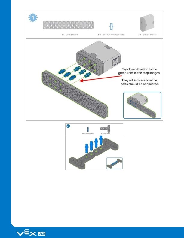
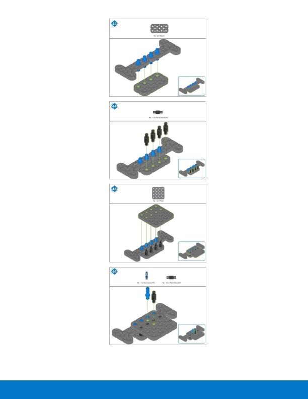
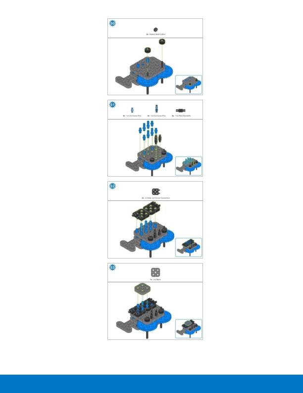
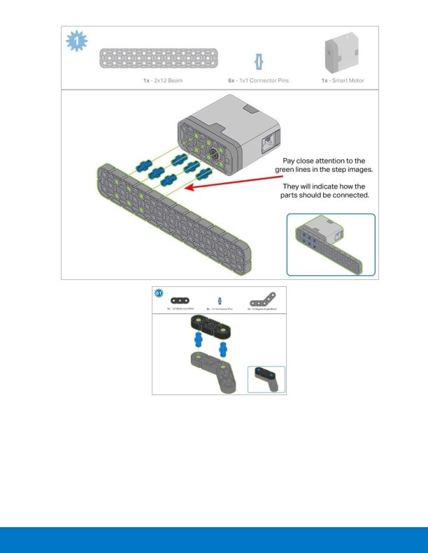
Build Instructions - Drivetrain + Distance Build Instructions Summary Drivetrain + Distance Building Instructions (19 steps): o Right Wheel: steps 1 to 6 o Left Wheel: steps 7 to 12 o Distance Sensor: steps 13 to 19 Building Tips for All Steps: o The section at the top of the step shows important information for the build. The first number under the image of the part (1 x, 2 x, 4 x, etc) is the number of that piece you will need in this step. The next information under the part image is the size and description of the part needed. o The finished step is illustrated in the box in the lower right corner.

o Play close attention to the green lines in the step images. They will indicate how the parts should be connected.
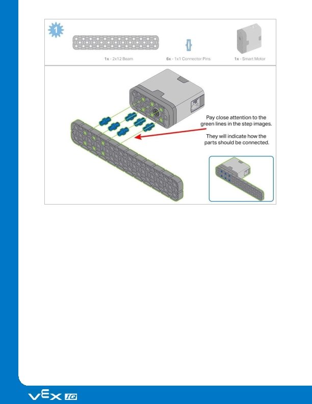

Step 1: Count all pieces before starting your build and have them readily available. Each team member should find the pieces for their section.

Step 2: When adding the 4 x Pitch Shaft, twist the pitch shaft to check for tension while turning. If it spins freely, it is not properly inserted into the motor.

Step 5: Make sure the gears fit together properly before locking the 2 x 12 Beam in place.

Step 6: After attaching the wheels, twist the wheel that has the shaft going into the motor. If the wheel spins freely and without tension, the 4 x Pitch Shaft has slipped out of place.

Step 8: When adding the 4 x Pitch Shaft, twist the pitch shaft to check for tension while turning. If it spins freely, it is not properly inserted into the motor.

Step 11: Make sure the gears fit together properly before locking the 2 x 12 Beam in place.

Step 12: After attaching the wheels, twist the wheel that has the shaft going into the motor. If the wheel spins freely and without tension, the 4 x Pitch Shaft has slipped out of place. Step 14: Make sure the Gyro is placed the correct way to allow correct cable access.

Step 18: The orange arrows mean spin the build around.

Step 19: When attaching the Distance Sensor, do not push on either of the two mesh covered openings. This will damage the sensor. Ensure the sensor is placed in the correct way to allow cable access.
:")
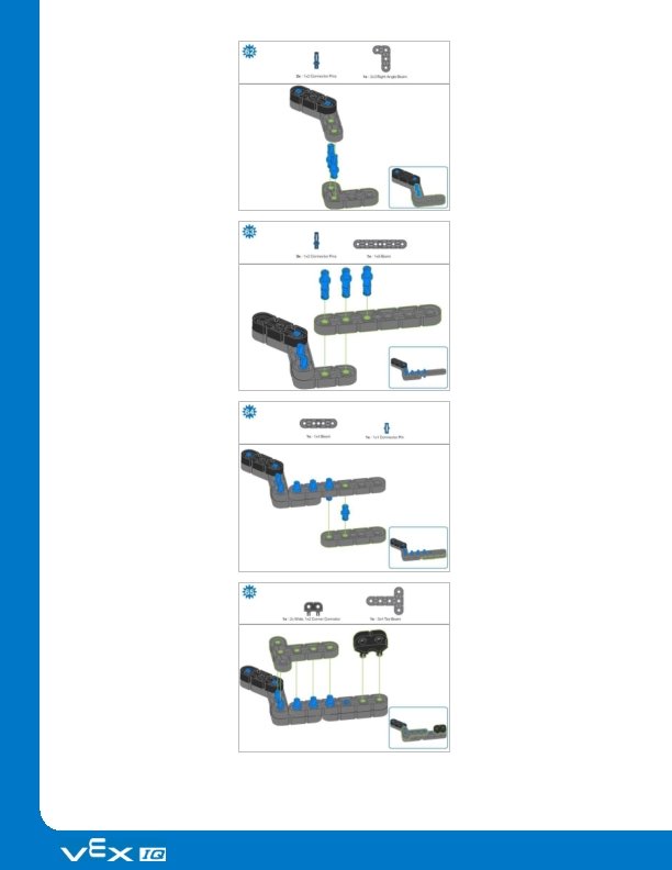
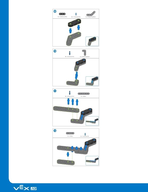
Build Instructions - Robot Frame Build Instructions Summary Robot Frame Building Instructions (22 steps): o Cargo Holder: steps 20 to 28 o Arm Base: steps 29 to 41 Building Tips for All Steps: o The section at the top of the step shows important information for the build. The first number under the image of the part (1 x, 2 x, 4 x, etc) is the number of that piece you will need in this step. The next information under the part image is the size and description of the part needed. o The finished step is illustrated in the box in the lower right corner.

o Play close attention to the green lines in the step images. They will indicate how the parts should be connected.
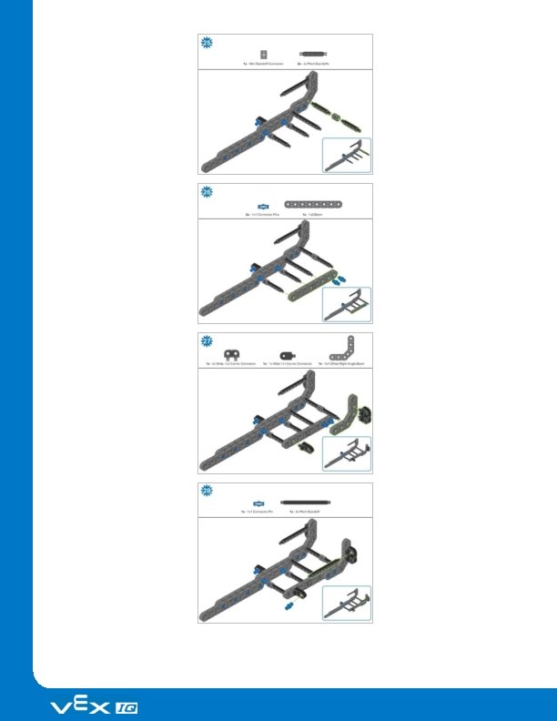

Step 31: The orange arrows mean spin the build around.

Step 33: Make sure the Bumper Switch is placed in the correct way to allow cable access.

Step 36: Make sure your Smart Motor is are oriented in the correct direction (the hole for the shaft is on the bottom)

Step 38: Make sure that the Touch LED is placed in the correct way to allow cable access. Step 39: The orange arrows mean spin the build around.

Step 40: Instead of individual parts, the completed sections of the build needed are shown in the section at the top. When adding the Step 37 Assembly, twist the pitch shaft to check for tension while turning. If it spins freely, it is not properly inserted into the motor. Step 41: Instead of individual parts, the completed sections of the build needed are shown in the section at the top. The orange arrows mean spin the build around.
: o Arm:")
Build Instructions - Arm Build Instructions Summary Arm Building Instructions (19 steps): o Arm: steps 42 to 60 Building Tips for All Steps: o The section at the top of the step shows important information for the build. The first number under the image of the part (1 x, 2 x, 4 x, etc) is the number of that piece you will need in this step. The next information under the part image is the size and description of the part needed. o The finished step is illustrated in the box in the lower right corner.

o Play close attention to the green lines in the step images. They will indicate how the parts should be connected.

Step 48: Make sure the gears fit together properly before moving on to the next step. Step 49: Turn one of the black shafts in the center of the gear to make sure they are together and both turn at the same time before adding the 4 x 4 Plate.

Step 56: Instead of individual parts, the completed sections of the build needed are shown in the section at the top.

Step 59: Instead of individual parts, the completed sections of the build needed are shown in the section at the top.

Step 60: Make sure your Smart Motor is are oriented in the correct direction (the hole for the shaft is on the right). After adding motor, turn one of the gears to check for tension while turning. If it spins freely, it is not properly inserted into the motor.
: o Claw:")
Build Instructions - Claw Build Instructions Summary Claw Building Instructions (22 steps): o Claw: steps 61 to 82 Building Tips for All Steps: o The section at the top of the step shows important information for the build. The first number under the image of the part (1 x, 2 x, 4 x, etc) is the number of that piece you will need in this step. The next information under the part image is the size and description of the part needed. o The finished step is illustrated in the box in the lower right corner.

o Play close attention to the green lines in the step images. They will indicate how the parts should be connected.

Step 67: Make sure that the 100 mm Travel Tire fits snugly in the grove of the 2 x Wide, ½ Corner Connector. Step 68: The orange arrows mean spin the build around.

Step 75: Make sure that the 100 mm Travel Tire fits snugly in the grove of the 2 x Wide, ½ Corner Connector.

Step 76: The orange arrows mean spin the build around. Step 77: Instead of individual parts, the completed sections of the build needed are shown in the section at the top. Step 78: Instead of individual parts, the completed sections of the build needed are shown in the section at the top.

Step 80: The sensor being attached is the Color Sensor. Ensure the sensor is placed in the correct way to allow cable access. Step 81: Instead of individual parts, the completed sections of the build needed are shown in the section at the top.
:")
Build Instructions - Assembly and Wiring Build Instructions Summary Assembly and Wiring (11 steps): o Final Assembly: steps 83 to 93 o The group is also responsible for making sure the sensors and motors are attached to the correct ports using the designated Smart Cables. – Port 1: Left Wheel – Port 2: Touch LED – Port 3: Color Sensor – Port 4: Gyro Sensor – Port 6: Right Wheel – Port 7: Distance Sensor – Port 8: Bumper Switch – Port 10: Arm Motor – Port 11: Claw Motor Building Tips for All Steps: o The section at the top of the step shows important information for the build. The first number under the image of the part (1 x, 2 x, 4 x, etc) is the number of that piece you will need in this step. The next information under the part image is the size and description of the part needed. o The finished step is illustrated in the box in the lower right corner. o Play close attention to the green lines in the step images. They will indicate how the parts should be connected. Building Tips for Steps 87 -89:

o The solid green numbers represent the numbered port the cable will be connected into. The outlined green number indicates the sensor that cable will connect into. Use the indicated Smart Cable for each sensor or motor. When attaching the Smart Cables, make sure they are tucked away so as to not block the Smart Sensors or interfere with the Clawbot’s movement.

Step 83: Instead of individual parts, the completed sections of the build needed are shown in the section at the top.

Step 84: Instead of individual parts, the completed sections of the build needed are shown in the section at the top. Step 85: Instead of individual parts, the completed sections of the build needed are shown in the section at the top. Step 86: Make sure the Smart Radio is pushed in securely. Make sure the Robot Battery is oriented the correct way before inserting. The orange arrows mean spin the build around.

Step 87: The Smart cable for the Arm Motor can be tucked under the Brain and plugged into the correct port (port 10). Step 89: The orange arrows mean spin the build around.

Step 90: Instead of individual parts, the completed sections of the build needed are shown in the section at the top. The orange arrows mean spin the build around. Step 91: Instead of individual parts, the completed sections of the build needed are shown in the section at the top. The orange arrows mean spin the build around. Step 92: When adding the 8 x Pitch Shaft, twist the pitch shaft to check for tension while turning. If it spins freely, it is not properly inserted into the gears.

Step 93: The solid green numbers represent the numbered port the cable will be connected into. The outlined green number indicates the sensor that cable will connect into. Use the indicated Smart Cable for each sensor. When attaching the Smart Cables, make sure they are tucked away so as to not block the Smart Sensors or interfere with the Clawbot’s movement.

Exploration Now that you have built the Clawbot IQ, let’s take some measurements to get more familiar with its dimensions. This will help us create and solve mazes, tunnels, and other challenges. Record the measurements in your engineering notebook. How long is the Clawbot? How wide? How tall? You can use a ruler (inches or cm) or one of the beams to measure. When using the VEX IQ Beam as a measurement tool, count the spaces between the grooves on the side of the beam as a unit. If you wanted to line up three Clawbots in a row, touching front to back, how much space would you need? How many Clawbots would you need if you wanted to line them up, touching front to back, around the perimeter of a square that was 64 inches (162. 4 cm) long on each side?

Test your build, observe how it functions, and fuel your logic and reasoning skills through imaginative, creative play.

Loops: Simplifying Repetitive Action Simplify Projects with Loops We, as humans, repeat many behaviors in our daily lives. From eating and sleeping to brushing our teeth and walking our dogs, much of what we do each day is repetitive. In math class, we know that multiplying a number by zero, will always equal zero or that multiplying a number by one will always equal itself, no matter how many times we do it. While we have a tendency to repeat our behaviors, our instructions can sometimes be simplified. For example, if you’re using a recipe to bake a cake, it wouldn’t tell you to “add 1 cup of sugar, add 1 cup of sugar. ” Instead, it would simply tell you to add four cups of sugar. With robots, Loops help us simplify our projects. Instead of adding the same block four times, for example, we can use a Loop to tell the robot to perform the same behavior four times, saving time and space as we build our projects. Imagine a task that a robot might perform

that would require repetition to complete the task. Those behaviors, along with a Loop block from the Control block category, are what you would need to project to achieve the task.

Controller Exploration - Part 1 Ready for Programming! Clawbot is ready for programming with the Controller! This exploration will give you the tools to be able to program some basic movements within a project. VEXcode IQ Blocks that will be used in this exploration: The forever block—this block loops a set of blocks forever. A forever loop can only be exited by using a break block or by stopping the program. The forever block will not stop repeating unless a break block is placed inside of it. Here is an example of a break block being used to exit a forever loop. The set motor velocity block—sets the speed of the motor.

The velocity can be set to either percent or rpm: The spin block—spins a motor until stopped. The motor would be stopped by stopping the program. The position of controller block—reports the position of the Joystick on the controller along an axis. The Joystick begins at 0 when centered on the axis. o This block will enable the Controller to determine a motor’s velocity. To do so, drag this block from the Toolbox over the velocity in the set motor velocity block; this will replace the default velocity with the Controller position of your choosing. To find out more information about any of these blocks, open Help, and select the block(s) about which you have questions. The Builder in each group should get the hardware required. The Recorder should get the group’s engineering notebook. The Programmer should open VEXcode IQ Blocks. Hardware/Software Required: Quantity Hardware/Other Items 1 Clawbot 1 Charged VEX IQ Robot Battery 1 VEX IQ Radio

Quantity Hardware/Other Items 1 Controller 1 Tether Cable 1 VEXcode IQ Blocks 1 USB Cable (if using a computer) 1 Engineering Notebook

Controller Exploration - Part 2 1. Preparing for the exploration Before you begin the activity, do you have each of these items ready? The Builder should check each of the following: Are all the motors and sensors plugged into the correct port? Are the smart cables fully inserted into all of the motors and sensors? Is the Brain turned on? Is the battery charged? Is the Controller paired with the Robot Brain? Is the Radio inserted into the Controller? 2. Open and Save the Example Project Before you begin your project, the Programmer needs to select the correct template from the folder of example projects in VEXcode IQ Blocks. The Clawbot with Controller Template is used for this exploration. The Programmer should complete the following steps: Open the File menu.

Select Open Examples. Use the filter bar at the top of the application and select "Templates. " VEXcode IQ Blocks contains many different templates. You’ll use one of them in this exploration. For help and tips on using templates, check out the Using Examples and Templates tutorial. Select and open the Clawbot with Controller template. Save your project as clawbot. Controller. Check to make sure the project name clawbot. Controller is now in the window in the center of the toolbar.

Controller Exploration - Part 3 1. Controller Programming What are the benefits of using a forever block? Build this project as shown below without the forever block: What do you think would happen if this program were run? Discuss as a group. The Recorder should write down the team’s prediction in the engineering notebook.

2. Navigate a Slalom Course! Slaloms are courses which the participant must navigate around the set flags, or markers. Ski slaloms are a popular winter sport and are included in the Winter Olympics. Now that the Controller is paired and the project is downloaded, you are ready to move your Clawbot using the Controller! The Builder and the Programmer should collect the four classroom items you will use as flags in your slalom from the teacher. The Builder, Programmer, and Recorder should collaborate to set them in place for the Driver to navigate the Clawbot around, according to the slalom diagram. The Driver should download the clawbot. Controller project. If there any questions about how to download a project, check out the Download and Run a Project tutorial.

3. Robo-Slalom Use the Controller to move your Clawbot along the outside of each “flag. ” The robot’s path must prevent it from touching any flag, and allow it to cross the finish line.

The Driver should run the project and drive the Clawbot forward and reverse, and turn left and right using both Joysticks. The Recorder should time how long it takes for the Clawbot to complete the course. Document the times in the engineering notebook. How fast can you get Clawbot through the Slalom course?

Become a 21 st century problem solver by applying the core skills and concepts you learned to other problems.

Real World Connection A conveyor belt moves chocolates along a mechanical assembly line. Loops in Manufacturing Robots are capable of doing the same task over and over by using loops. There are many advantages to having robots do repetitive tasks. Robots do not get tired, and do not need breaks (as long as they have constant power). For this reason, robots have become instrumental in manufacturing where robots can continuously do tasks which would be more difficult, or even dangerous, for humans. An example of an industry which has benefited from robots doing repetitive tasks is the candy industry. Robots such as ABB’s Flexpicker can use a vacuum attachment to pick up hundreds of candies per minute. Robots can be programmed to exert the right amount of force for very delicate candies so they don’t get crushed. Robots on the assembly line can also use vision sensors to identify candies which are misshapen and not pick them up. Programming robots with loops can help make manufacturing, like the candy industry, more efficient.

Let’s Compete! Students competing in the Teamwork Challenge Two Types of Challenges Using loops to control the Clawbot with the Controller has allowed the driver to navigate a slalom. Practicing driving the Clawbot is a useful task which can help you prepare for one of the challenges in the VEX Robotics World Championship. There are two types of challenges the teams will tackle. In the Robotic Skills Challenge, teams try to score as many points as possible with their robotic build in two types of matches. Driving Skills Matches are entirely driver controlled and Programming Skills Matches are autonomous with limited student interaction. The drivers of the Driving Skills Matches switch halfway through the match and so, it is important that both teammates practice driving and come up with strategies for scoring more points. The second type of challenge is the Teamwork Challenge, in which two robots compete in

the challenge as an alliance in 60 second long matches, working together to score the most points.

Is there a more efficient way to come to the same conclusion? Take what you’ve learned and try to improve it.

Event-Based Programming: Communication Among Blocks Event-based programming If your dog brings you his leash or sits by the door, he’s letting you know that he needs to go outside. In school, when your teacher asks a question and sees you raise your hand, she knows that you believe you know the answer and would like to answer the question. These behaviors are also known as “triggers. ” Your dog knows that bringing you his leash or sitting by the door is the trigger that lets you know he needs to go outside. So, when you see him sitting by the door with his leash, you react to the trigger by taking him outside. Raising your hand is the trigger that lets the teacher know you would like to answer her question. The teacher then reacts to the trigger by calling upon you. Event-based programming in robotics is when certain robot behaviors trigger the robot to do certain things or react to certain triggers. To learn more about event-based programming, watch our tutorial on events by clicking Tutorials in the toolbar and selecting the Events tutorial.

Controller: Clawbot Control Now, you’re ready to download the example project and use the Controller to operate the Clawbot, its Arm, and its Claw, all at the same time! The Builder in each group should get the hardware required. The Recorder should get the group’s engineering notebook. The Programmer should open VEXcode IQ Blocks. Hardware/Software Required: Quantity Hardware/Other Items 1 Clawbot 1 Charged Robot Battery 1 VEX IQ Radio 1 Controller 1 Tether Cable 1 VEXcode IQ Blocks 1 USB Cable (if using a computer) 1 Engineering Notebook Before you begin the activity. . . Do you have each of these items ready? The Builder should check each of the following: Before you begin the activity, do you have each of these items ready? The Builder should check each of the following: Are all the motors and sensors plugged into the correct port? Are the smart cables fully inserted into all of the motors and sensors? Is the Brain turned on? Is the battery charged?

Is the Controller paired with the Robot Brain? Is the Radio inserted into the Controller?

Remix Challenges - Part 1 Before you begin your project, the Programmer needs to select the correct example project. The Clawbot Control example project contains the Clawbot motors and sensors configuration. If the template is not used, your robot will not run the project correctly. The Programmer should go to the file menu, Open Examples, filter by selecting "Events", then select the Clawbot Control example project. Save the project. Check to make sure the project name Clawbot Control is now in the window in the center of the toolbar. The Clawbot is now properly configured, and the Clawbot Control project is ready for use. Now, take a look at how the blocks are being used in this project. In your engineering notebooks, make the following predictions: What’s happening when you run this project? What will the Clawbot be able to do? What would happen if we didn’t use the not block in this project?

Remix Challenges - Part 2 Activity A: Grab an object! The goal of this activity is to grab and release an object with the Clawbot using the Controller. Here are some steps to guide your team: Builder: Place your group’s object on the floor and make sure your Clawbot has enough space to move without interfering with other groups. Driver: List the steps the Clawbot will need to grab the object. Be sure to include which buttons you’ll use to accomplish this task! Recorder: Write the steps the Driver lists in the engineering notebook. Programmer: Click the Download button in the Toolbar to download the Clawbot Control project to the Robot Brain. Programmer: Check to make sure your project has downloaded to the Clawbot’s Brain by looking at the Robot Brain’s screen. The project name, Clawbot Control, should be listed in slot 1. Driver: Run the project on the Clawbot by making sure the project is highlighted and then press the Check button. Driver: Grab and release an object with the Clawbot using the Controller. Congratulations! You have grabbed an object with your Clawbot using the Controller! Were there any differences between the Driver’s predictions and the actions he or she had to take during the activity? If so, the Recorder can add them to your engineering notebook.

Remix Challenges - Part 3 Activity B: Competitive Challenge! The goal of this activity is to use your Clawbot skills to collect several objects, one at a time, and return them to a location faster than the other groups in your class. Good luck! Here are some steps to guide your team: Builder: Move your group’s objects behind the object retrieval area your teacher has established, and make sure your Clawbot has space to move without interfering with other groups. Driver: List the steps the Clawbot will need to grab each object and return them to home base. Be sure to include which buttons you’ll use to accomplish this task! Recorder: Write the steps the Driver lists in the engineering notebook. Programmer: Using the classroom clock or a watch, keep time and report it to the Recorder. Driver: Retrieve each object as quickly as you can. Recorder: Record the time in your engineering notebook. Congratulations! You have collected all three of your group’s objects, returned them to home base with your Clawbot using the Controller!

Activity C: Teamwork Challenge! The goal of this activity is to use your Clawbot and teamwork skills in a relay race. The team will be responsible for moving an object across a three meter course in the fastest time possible. Player 1: Pick the object and carry it to the one meter line. Drop the object. Player 2: Pick up the object and carry from the one to the two meter line. Drop the object. Player 3: Pick up the object and carry from the two meter line to the finish line. Drop the object in the goal area.

Remix Questions Answer the following questions in your engineering notebook after completing Activities A, B, and C. The set motor stopping block is set to “hold” for both the Arm Motor and the Claw Motor. What would happen if those blocks were removed? The spin and stop blocks that control the Arm and Claw Motors are nearly identical. If you were to create this program yourself, how could you save time and avoid dragging every individual block into the workspace over and over?

Understand the core concepts and how to apply them to different situations. This review process will fuel motivation to learn.

Review You have accomplished a lot in this STEM Lab! The following questions will help you think back over everything you have learned. You can only answer once, so think carefully before you submit! 1. Which of the following about loops is true? o A loop can repeat a robot’s actions forever. o A loop can repeat a robot’s actions a set number of times. o A loop shortens the number of blocks needed in a project. o All of these answers are correct. 2. Mitchel wants to program his Clawbot to continuously run in a square path around the room without stopping. Which is the best block to use to accomplish this? o The wait until block o The repeat block o The forever block o The repeat until block 3. To start a project in VEXcode IQ Blocks, which is the correct order of steps? o Save the project, open the file menu, name the project, select examples, choose a template. o Open the file menu, choose a template, name the project, select examples, save the project. o Open the file menu, select examples, choose a template, name the project, save the project. 4. Jose has created a project to make his Clawbot drive forward, set the Touch LED color to blue, and play a sound. He wants to repeat this series of behaviors 4 times. How many total inches forward has the Clawbot traveled when the loop is complete?

o 6 o 4 o 8 o 42 5. Terrance is using a repeat block with 4 blocks inside of it. The repeat block is set to repeat 11 times. What is the right mathematical notation which describes how many total blocks the robot will run through in the project, including the repeat block? o 1 + (4 x 11) o 4 x 11 o 4 + 11 o 1 + 4 + 11 6. True or false: The Joystick, L buttons, and R buttons are all triggers for event-driven programming in the Clawbot Control Example Project. o True o False 7. In the following project, what function does the set motor stopping blocks do?

o They stop the motors from moving after the loop has ended. o They do not allow Controller to move the Arm and Claw. o They allow the motors to spin freely. o They prevent the Arm from dropping and/or the Claw from closing when the buttons that control their motors are released. 8. Clawbot has a challenge to navigate a maze course to land on one of the red dots. The Clawbot starts on the box with the star. Clawbot can only navigate on the white squares. What is the shortest number of squares the Clawbot could travel to land on one of the red dots?

o 9 o 7 o 3 o 12

Additional information, resources, and materials.

Knowledge Base Articles Links to the VEX Robotics Knowledge Base Articles for this STEM Lab: How to Turn On/Off a VEX IQ Robot Brain https: //kb. vex. com/hc/en-us/articles/360035952571 -How-to-Turn-On-Off-a-VEX-IQ-Robot. Brain How to Read Indicator Lights on the VEX IQ Robot Brain https: //kb. vex. com/hc/en-us/articles/360035590672 -How-to-Read-Indicator-Lights-on-the. VEX-IQ-Robot-Brain How to Navigate the VEX IQ Robot Brain https: //kb. vex. com/hc/en-us/articles/360035952331 -How-to-Navigate-the-VEX-IQ-Robot. Brain How to Connect VEX IQ Devices to Smart Ports https: //kb. vex. com/hc/en-us/articles/360035952151 -How-to-Connect-VEX-IQ-Devices-to. Smart-Ports How to Install or Remove the VEX IQ Robot Battery https: //kb. vex. com/hc/en-us/articles/360035951991 -How-to-Install-or-Remove-the-VEXIQ-Robot-Battery How to Charge the VEX IQ Robot Battery https: //kb. vex. com/hc/en-us/articles/360035955011 -How-to-Charge-the-VEX-IQ-Robot. Battery How to Use the Autopilot Program in the Demos Folder https: //kb. vex. com/hc/en-us/articles/360035952031 -How-to-Use-the-Autopilot-Program-inthe-Demos-Folder Best Practices for Preserving the VEX IQ Robot Battery’s Life https: //kb. vex. com/hc/en -us/articles/360035953671 -Best-Practices-for-Preserving-the- VEX-IQ-Robot-Batterys-Life Ideas for Organizing the VEX IQ Super Kit https: //kb. vex. com/hc/en-us/articles/360035590332 -Ideas-for-Organizing-the-VEX-IQSuper-Kit VEX IQ Brain Status (USB Cable) https: //kb. vex. com/hc/en-us/articles/360035955411 -How-to-Understand-the-VEX-IQBrain-Status-Icon-USB-VEXcode-IQ-Blocks Links to VEXCode IQ Blocks Knowledge Base Articles for this STEM Lab: How to Begin a New Project in VEXcode IQ Blocks https: //kb. vex. com/hc/en-us/articles/360035954551 -How-to-Begin-a-New-Project. VEXcode-IQ-Blocks

How to Download and Run a Project https: //kb. vex. com/hc/en-us/articles/360035591232 -How-to-Download-and-Run-a-Project. VEXcode-IQ-Blocks How to Save a Project on Windows https: //kb. vex. com/hc/en-us/articles/360035954531 -How-to-Save-a-Project-on-Windows. VEXcode-IQ-Blocks How to Save a Project on mac. OS https: //kb. vex. com/hc/en-us/articles/360035954511 -How-to-Save-a-Project-on-mac. OSVEXcode-IQ-Blocks How to Save a Project on Chromebook https: //kb. vex. com/hc/en-us/articles/360035955351 -How-to-Save-on-a-Chromebook. VEXcode-IQ-Blocks How to Download to a Selected Slot on the Brain https: //kb. vex. com/hc/en-us/articles/360035591292 -How-to-Download-to-a-Selected-Sloton-the-Brain-VEXcode-IQ-Blocks

Identifying Angle Beams How to Identify the Different Angles of the Angled Beams There are four different types of beams that have a bend at an angle: 30 o Angle Beams, 45 o Angle Beams, 60 o Angle Beams, and Right Angle (90 o) Beams. There also three types of Right Angle Beams: 3 x 5, 2 x 3, and Offset. The best way to tell which angles are which is to stack the beams on top of each other. Then you can compare how they look. You can also use a protractor to measure the angle of the beam.

Installing Rubber Shaft Collars Using your hand to warm a Rubber Shaft Collar Rubber Softens as it gets Warm Hold the Rubber Shaft Collars in your hand for 15 -30 seconds before you slide them onto a shaft. Holding the Rubber Shaft Collar in your hand will warm and soften the rubber to make it easier to slide onto a shaft.

Removing Connectors from Beams and Plates Using a pitch shaft to remove a corner connector How to Easily Remove Connectors You can easily remove corner connectors from beams or plates by placing a metal shaft through one of the holes of the corner connector and pulling outward while holding down the beam or plate.

Removing Pins from VEX IQ Beams and Plates Removing a pin from a plate assembly using a beam How to Easily Remove Pins from Beams and Plates You can quickly remove connector pins from beams or plates by pressing a beam against the back of the pin, which partially pushes the pin out, so you can remove it with your fingers. You can use this technique to more easily remove pins from individual plates and beams, or from built structures.

Removing Standoffs from Mini Standoff Connectors Removal of a standoff from a Mini Standoff Connector How to Easily Remove Parts from Mini Standoff Connectors Standoffs and Mini Standoff Connectors can be separated by pushing a shaft through the Mini Standoff Connector. The same technique can be used for parts with similar ends in Mini Standoff Connectors, such as pins.

Supporting Shafts using Rubber Shaft Collars Unsupported Shaft Rubber Shaft Collar Added to Shaft Supported Shaft Supporting a shaft with a Rubber Shaft Collar How to Support Shafts with Rubber Shaft Collars Shafts can fall out of place or alignment very easily if they aren't supported properly. You can make a shaft more secure and prevent it from falling out of place by putting a Rubber Shaft Collar before the end of it. You can then connect the shaft to a support structure with the shaft collar positioned against it. That will allow the shaft to turn but will prevent it from wobbling or falling out.

Supporting Shafts using Shaft Bushings Unsupported Shaft Bushing Added to Shaft Supported Shaft Supporting a shaft with a Shaft Bushing How to Support Shafts Using Shaft Bushings Shafts can fall out of place or alignment very easily if they aren't supported properly. You can make a shaft more secure and prevent it from falling out of place by putting a bushing at the end of it. You can then connect that bushing into another beam or additional part. That will allow the shaft to turn but will prevent it from wobbling or falling out.

Popups within this STEM Lab

Stop and Discuss — Driving Forward and Reverse. Exploration These steps are very important because they will begin almost all programming explorations. For example you can say, “Let’s pause here for a moment. As a group summarize the steps we just completed. Record your summary in your engineering notebook. ” Remind the students that each group should have someone in the Recorder role. Allow students approximately 5 - 10 minutes to summarize the steps. If time allows, ask each group to share their summary. An example of what the summary could look like: Open the file menu Select examples Choose a template Name the project Save the project

Program Autopilot to Move Forward The drive block can be used to drive a robot forward or backwards. In order to move the Autopilot in reverse, the student will just need to change the drive block to “reverse. ” Anything editable inside of the blocks is called a parameter. When using the drive block, it is important to note that block used by itself does not cause the robot to stop moving. For example, if the project below was downloaded and run on a robot, the robot would drive forward without stopping.

In order to get Autopilot to stop moving, the X would need to be pressed on Autopilot’s Robot Brain. Pressing the X button on the Robot Brain ends the project and stops all of the motors. In the Forward and Reverse exploration, the students will just use the drive block. However, other blocks can be used to program basic movements. If the student wants to move a specific distance, they can use the drive for block.

Students can change the distance traveled by adjusting the parameter in the block. In the project above, the distance was changed from 1 inch to 30 inches. Students can program their robot to move in mm or inches.

play sound Block Students will be adding a play sound block to their program.
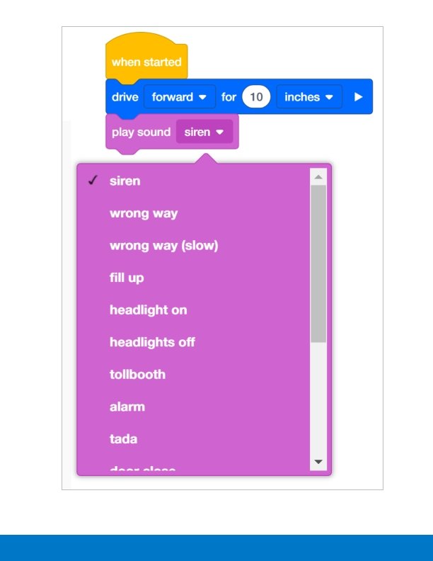

With this example, the robot will drive forward for 10 inches and then play the siren sound. The drive for block in this project is a waiting block. This means that the block will pause the rest of the stack until it has been completed. Therefore, the Autopilot will drive forward for 10 inches and then make the siren sound. The drive for block can be expanded to become a non-waiting block, as in the example below. With this program, as soon as Autopilot starts driving, it will immediately play the siren sound. This is because the drive for block is now set to non-waiting. It is NOT going to pause the stack until it has been completed. Some of the blocks in VEXcode IQ Blocks can be changed from waiting to non-waiting by selecting the arrow at the end of the block.

The play sound block is also a non-waiting block. Therefore, when the project below is run, Autopilot will play the siren and immediately begin to drive forward.

Organizing Students into Groups for Exploration Organize the students into groups before beginning the exploration. Students can be organized into groups of two to four students when participating in the exploration. The following roles can be utilized during the exploration: Builder — This person checks that the robot is properly built and ready (e. g. , Are all the motors and sensors plugged into the correct ports? Is the Robot Brain turned on? ) before a project is run. Programmer — This person will use the drive block to create a project on the computer or tablet. This person will also download the project to the robot. Driver — This person selects the project and then runs it on the robot. This person will also be the one to retrieve the robot after it as run. Recorder — This person writes down all of the group answers/reflections in the engineering notebook. If there are two students in each group, the students can each choose two roles. If there are three students in a group, one of the students can choose to do two roles. If there are four students in a group, each student can have one role. Provide the list of roles and their definitions to the students. Once students are in their groups, allow the members to choose their role. Circulate the classroom and make sure that every student has a role. There is an optional collaboration rubric. Remind the students of roles throughout the exploration. For roles to work, students have to feel as though they will be held accountable for fulfilling those roles. Therefore, interject if you see a student taking over someone else’s role or not fulfilling their assigned role. Reminding students about who is supposed to be doing what can be a useful intervention.

Motivate Discussion — Driving Forward and Reverse Exploration Motivate Discussion Q: Ask the students what they think would happen if they added a stop driving block to their project. (Have them record their answers in their engineering notebooks). A: With this project, the robot would not move at all. This is because the project is telling the robot to drive forward, but then it is immediately telling it to stop. This happens so quickly that the robot does not move. If students did answer that Autopilot would move forward and then stop, the students could then be asked how far the robot would move forward before it stopped. This could lead into the discussion that the project moves very quickly through the commands and eventually lead the students to realize that because the project does move so quickly through the commands that the robot does not move. The discussion could then be a good introduction to the use of the wait block:

By using the wait block, a student can program a robot to drive forward for a certain amount of time. For example, in the project below, a robot would drive forward for 5 seconds and then stop.

Exploration Roles Students can be organized groups of two to four students when participating in the exploration. The following roles can be utilized during the exploration: Builder -- This person checks that the robot is properly built and ready (e. g. Are all the motors and sensors plugged into the correct port? Is the Robot Brain turned on? ) before a project is run. Programmer -- This person will recreate the project provided in the exploration on the computer or tablet. This person will also download the project to the robot. Driver -- This person selects the project and then runs it on the robot. This person will also be the one to retrieve the robot after it has run. Recorder -- This person writes down all of the group answers/reflections in the engineering notebook. If there are two students in each group, the students can each choose two roles. If there are three students in a group, one of the students can choose to do two roles. If there are four students in a group, each student can have one role. Provide the list of roles and their definitions to the students. Once students are in their groups, allow the members to choose their role. Circulate the classroom and makes sure that every student has a role. There is an optional collaboration rubric on this page. Remind the students of roles throughout the exploration. For roles to work, students have to feel as though they will be held accountable for fulfilling those roles. Therefore, interject if you see a student taking over someone else’s role or not fulfilling their assigned role. Reminders about who is supposed to be doing what can be useful interventions.

Drive Forward and Reverse Exploration Outline The outline for the Drive Forward and Reverse Exploration is as follows: Introduce the drive block Do a quick troubleshooting check that the VEX IQ Autopilot is ready Start a new project in VEXcode IQ Blocks Rename and save the project Create the Drive project that moves Autopilot forward Download and run the project Change the Drive project to move Autopilot in reverse Download and run the project Wrap up the activity with a discussion

drive for Activity B Program Answers Bonus:

Demonstrating how the Drivetrain to Drive Blocks are Related Have an Autopilot robot to demonstrate for the students. Introduce to students the drive block. Read the description of the drive block in the Help. Either have VEXcode IQ Blocks displayed in front of the classroom, or have each student group follow along at their workstation. When discussing the descriptor and purpose of the block, ask the students if they can identify what a Drivetrain is. Discuss with the students that a Drivetrain consists of: A rectangular Chassis (the structure of a mobile robot that holds wheels, motors, and/or any other hardware used to make up a Drivetrain) Two Motors Four Wheels Gears transmitting Power from the Motors to all Wheels Use Autopilot robot to show the students the parts of the Drivetrain during the discussion. Next, gently turn one of the wheels that is connected to a motor. Show the students that because of the gears, even though the force is being applied to one wheel, both wheels are moving. Tell the students that instead of moving the wheels by hand, we’ll use the drive block to program the motors to run and the wheels to turn.

Cultivating a Positive Learning Environment Recognize and reinforce positive behaviors by creating a list of specific behaviors you want to encourage. Examples could include: Students self-organizing with the roles within a group Students performing each of their roles well within a group Students handling the robot and the computers/tablets with care Students praising and encouraging one another during the exploration When students use these behaviors, praise them immediately. Be specific when offering praise. For example, instead of saying, “good job, ” you could instead say, “good job carefully returning the Autopilot robot to the correct spot. ”

Configuration for Autopilot's Motors and Sensors The configuration for Autopilot’s motors and sensors are: Port 1: Left Motor Port 2: Distance Sensor Port 3: Color Sensor Port 4: Gyro Sensor Port 5: Touch LED Port 6: Right Motor Port 8: Bumper Switch Port 9: Bumper Switch

Building the Autopilot Robot with a Team Teacher Toolbox The build instructions will show students step-by-step instructions on how to build the Autopilot Robot. The Build Instruction Tips section will point out additional information for specific steps which will help students be successful with their build, so be sure to point out that section to students. There is an optional rubric to evaluate the robot build on this page. If any rubrics are used to evaluate students, review the rubric or pass out copies before students begin working so they are clear on how they will be assessed. Before starting the build, consider how your students will be organized. Will each student have their own robot, or will they work in pairs or teams? If working in teams, each student could build a portion of steps or each student could be given a role. The following roles can be utilized during the building of Autopilot: Right wheel — This person follows steps 1 -6 to build the right wheel of Autopilot. This person is also responsible for making sure that the motor gets plugged into the correct port (port 6). Left wheel — This person follows steps 7 -12 to build the left wheel of Autopilot. This person is also responsible for making sure that the motor gets plugged into the correct port (port 1). Sensors — This person follows steps 13 -26 to build the frame and attach the sensors. Robot Brain — This person follows steps 27 -30 to connect all of the components including the Robot Brain and making sure the sensors are attached to the correct ports. This person is also responsible for making sure that the battery is charged and ready. o Port 2: Distance Sensor o Port 3: Color Sensor o Port 4: Gyro Sensor o Port 5: Touch LED o Port 8: Bumper Switch o Port 9: Bumper Switch If there are two students in each group, the students can each choose two roles. If there are three students in a group, one of the students can choose to do two roles. If there are four

students in a group, each student can have one role. Provide the list of roles and their responsibilities to the students. Once students are in their groups, allow the members to choose their role. Circulate the classroom and make sure that every student has a role. There is an optional collaboration rubric on this page. Remind the students of roles throughout the exploration. For roles to work, students have to feel as though they will be held accountable for fulfilling those roles. Therefore, interject if you see a student taking over someone else’s role or not fulfilling their assigned role. Reminders about who is supposed to be doing what can be useful interventions.

Adjusting Parameters Students can change the distance traveled by adjusting the parameter in the block. In the program above, the distance was changed from 1 inch to 30 inches. Students can program their robot to move in mm or inches. How is the drive for block able to program a robot to move to a precise distance? In the Robot Configuration, you are able to specify the size of the wheels. For example, the typical wheel size for the Autopilot is 200 millimeters. This is the default setting in the Robot Configuration. However, what does wheel size actually mean? The listed wheel size is the actual wheel circumference. This means that every time the wheel completes one full rotation, it travels 200 millimeters. When the drive for block is programmed to move forward a specific amount of inches or millimeters, the programming logic inside of the drive for block performs math calculations. For example, if the drive for block is programmed to move forward 2000 millimeters, that means that the wheels have to travel 10 complete rotations. The drive for block is able to track each degree the wheel moves via the encoders that

are found within the motor. All of this math is completed with the programming logic built into the drive for block.
- Slides: 116