Classification of CrossSection Introduction To determine strength of


 element is assessed individually")


 cf = (b-tw-2 r)/2=110. 3 mm")


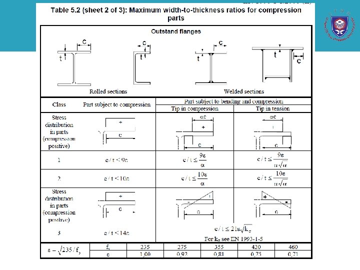
 Outstand flanges (Table 5. 2, Sheet 2)")
- clause 5. 5. 2 Flange")


- Slides: 18
Classification of Cross-Section
Introduction • To determine strength of the structural steel component, it requires the designer to consider the cross-sectional behaviour and the overall member behaviour. • Purpose of classification : to identify the extent to which the resistance and rotation capacity of cross sections is limited by its local buckling resistance. • Clause 5. 5. 1 and 6. 2 cover the cross-sectional aspects of the design process • In EC 3, cross-sections are placed into one of four behavioural classes depending upon the material yield strength, the width to thickness ratios (b/tf or d/tw) of the individual compression parts (e. g. web and flanges) within the cross-section and the loading arrangement.
• Local buckling – Local buckling exhibit local deformation of outstand • E. g. a flange of I beam – Local buckling occurs when the flange outstand to thickness ratio (b/tf) is high • Called flange buckling – The web is also subjected to compressive stresses from bending with a limiting to d/tw ratio beyond which web will buckle even though the axis of the axis remain straight • Called web buckling
Definition of classes • EC 3 classified four classes • In hot rolled design the majority of standard cross-section will be class 1, 2 or 3. • The four behavioural classes of cross-section defined by EC 3
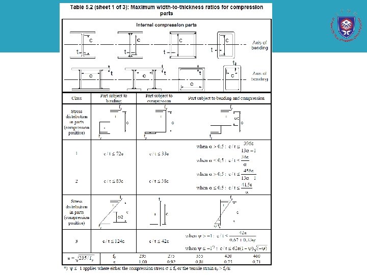
Assessment of Individual parts • Each compressed (or partially compressed) element is assessed individually against the limiting width to thickness ratios for Class 1, 2 and 3 elements as defined in Table 5. 2 of EN 1993 -1 -1. • An element that fails to meet the class 3 limits should be taken as Class 4. • The limiting width to thickness ratios are modified by a factor ε that is depend upon material yield strength • Where fy is the nominal yield strength of steel • *The section classification based upon the weaker element Definition of compression width c for common cases a) outstand flanges b) internal compression parts
Overall Cross-Section Classification • EC 3 allows the overall cross-section classification to be defined in one or two ways: – The overall classification is taken as the highest ( least favourable ) class of its component parts, with the exceptions that • Cross-sections with class 3 webs and class 1 or 2 flanges may be classified as Class 2 cross-sections with an effective web ( Clause 6. 2. 2. 4 of EC 3 -1 -1) • In the case where the web is assumed to carry shear force only (and not to contribute to the bending or axial resistance of the cross-section, the classification may be based on that of the flanges ( not allow for class 1) – The overall classification is defined by quoting both the flange and web classification.
Class 4 cross-section • Class 4 sections contain slender elements that are susceptible to local buckling in the elastic material range • Allowance for the reduction in resistance of Class 4 cross-section as a result of local buckling is made by assigning effective width to the class 4 compression element. • Calculation not include in Part 1 -1, instead is directed to Part 1. 3 for cold form sections, to Part 1. 5 for hot-rolled and fabricated sections and to Part 1. 6 for circular hollow section.
Example 2. 1 Cross section classification Q Determine the classifications and resistance Nc, Rd for a 254 x 73 UC in pure compression, assuming grade S 355 steel
A Outstand flanges (Table 5. 2, sheet 2) cf = (b-tw-2 r)/2=110. 3 mm cf/tf = 110. 3/14. 2 = 7. 77 Limit for class 2 flange 10ε = 10 x 0. 81 = 8. 14 > 7. 77 Hence flanges are Class 2 Web-internal compression part (Table 5. 2 sheet 1) cw = (h-2 tf-2 r) =200. 3 mm cw/tw = 200. 3/8. 6 = 23. 29 Limit for Class 1 web, 33ε = 26. 85 > 23. 29 Hence web are class 1 Overall cross-section classification is therefore Class 2
Classification under combined bending and axial force • Should be classified based on the actual stress distribution of the combined loadings – For simplicity , initial check carried out under the severe loading condition of pure axial compression. • If the section classified as Class 1 or 2, nothing to be gained by conducting additional calculations with the actual pattern of stress • If the classification is Class 3 or 4, it is advisable for economy to conduct a more precise classification under combined loading
Example 2. 2 Cross-section classification under combined bending and compression Q A member is to be designed to carry combined bending and axial load. In the presence of a major axis (y-y) bending moment and an axial force of 300 k. N, determine the cross-section classification of a 406 x 178 x 54 UB in grade S 275 steel
2. Cross-section classification (Clause 5. 5. 2) Outstand flanges (Table 5. 2, Sheet 2) Limit for class 1 flange = 9ε = 8. 32>6. 86 flanges are class 1 Web internal compression part (Table 5. 2, Sheet 1) Limit for Class 3 web = 42ε = 38. 8 > 46. 81 web is Class 4 Overall cross-section classification is therefore Class 4.
More precise approach (cross section classification under combined loading)- clause 5. 5. 2 Flange classification remains as Class 1. Web- internal part in bending and compression (Table 5. 2 sheet 1) From Table 5. 5 (sheet 1), for a class 2 cross-section: where α may be determined from equation below, for I and H section where the neutral axis lies within the web.
limit for a class 2 web = 456ε/13α-1 = 52. 33 > 46. 81 web is class 2 Overall cross section classification under the combined loading is therefore Class 2. Conclusion: For this section, a maximum axial force of 411 k. N may be sustained in combination with a major axis bending moment, whilst remaining within the limits of a Class 2 section
Tutorial 1 Q A welded I section is to be designed in bending. Determine the classification for a welded section with 200 x 20 mm flanges and a 600 x 6 mm web. Assuming grade S 275 steel