Class of Service Co S Quality of Service


- Slides: 46

Class of Service (Co. S) & Quality of Service (Qo. S) Sources: MPLS Forum V. Alwayn, Advanced MPLS Design and Implementation, Cisco Press E. W. Gray, MPLS Implementing the Technology, Addison Wesley B. Davie and Y. Rekhter, MPLS Technology and Applications, Morgan Kaufmann E. Osborne and A. Simha, Traffic Engineering with MPLS, Cisco. Press Slide 3 -1

What exactly is Co. S ? • Class of Service (Co. S): Groups of flows with same level of treatment Traffic differentiation or the ability to treat packets differently based on the application or packet’s importance or priority ü Service-level depends on state of the network and relative priority ü ü Ø • Example: 802. 1 p (Ethernet): No resources allocated per call, but differentiation of service level through priority. Relative priority, i. e. If network is congested service WILL degrade. Co. S is the ability of network devices to prioritize best-effort traffic No guarantees, highest class traffic get priority over other traffic when congestion happens ü No connections maintained end-to-end ü No per-flow state information maintained ü Slide 2

Class of Service • How many classes? ü Service provider specific. Example: Sprint has 4 classes (once) Ø Class A Premium Traffic: reserved for latency-sensitive applications only, e. g. , Vo. IP or Video over IP. Ø Class B Critical Traffic: highest class for data applications, e. g. , financial transactions Ø Class C Business Traffic: second class for data applications, e. g. database applications. Ø Class D Standard Traffic: This class is the default class, all traffic not prioritized in the above queues will be serviced in this class. Typical traffic for this queue is web browsing. Ø Bandwidth allocation recommendations (depends on ISPs): - 35% for Vo. IP, 25% for class B, 15% for class C, 25% for class D Slide 3

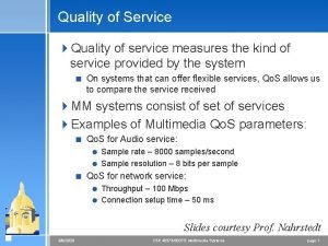
What exactly is Qo. S ? • Quality of Service (Qo. S) Mechanisms that allow network managers to contorl the mix of bandwidth, delay, jitter, and packet loss ü Hard allocation of resources ü What you pay for is what you get ü Ø • Qo. S is the ability to guarantee transmission characteristics end-to-end, not a device feature ü ü • Example: Connection set-up in an ATM network which allocates a fixed amount of resources Bandwidth, maximum end-to-end delay, maximum delay variation Signaling and end-to-end connections may be required Granularity and state information on a per flow basis Prioritization of service classes, bandwidth allocation, and congestion aviodance Evolution of standards: ü ü ü Best Effort Service: 1981 Integrated Services (Int. Serv): 1997 Differentiated Services (Diff. Serv): 1998 Slide 4

IP Qo. S – group discussion • • 2 -minute competition Identify types of policies/mechanisms in support of IP Qo. S ü Control policies Ø ü Admission control, policy control, congestion control, conditioning policy (between networks) Data or packet policies marking, classification Ø policing, dropping policy Ø Queuing / scheduling policy - LLQ, Priority Queuing - WFQ, CBWFQ - Hybrid - Adaptive queuing Slide 5 Ø

The Qo. S Pendulum Time Slide 6

IP Qo. S over MPLS • Service providers that offer IP services over an MPLS backbone must support IP Qo. S over their MPLS infrastructure – IP Qo. S over MPLS VPNs or MPLS traffic engineered paths. • MPLS can offer IP Qo. S services more efficiently over a range of platforms, including ATM LSRs. • Some useful Qo. S capabilities such as guaranteed -bandwidth LSPs can be supported over MPLS networks. Slide 7

Integrated Services (Int. Serv) Slide 3 -8

What is Int. Serv ? • An architecture allowing the delivery of the required level of Qo. S to real-time applications • Introduces a circuit-switched model to IP • A signalling-based system where the endsystem has to request the required service-level • RSVP – one of the signaling protocols of choice • A way of providing end-to-end Qo. S, state maintenance (for each RSVP flow and reservation), and admission control at each NE Slide 9

The Int. Serv Model Signalling required by end-stations for Resource-Reservation (RSVP) Sender Receiver Slide 10

The Int. Serv Model – Connection Set-Up Step 1: RSVP Path Step 2: RSVP RESV Step 3: Data Sender Receiver Slide 11

Int. Serv Characteristics • • Introduces the model of connections or flows • Int. Serv also defines a reservation spec called Rspec, which requests specific Qo. S levels and ther reservation of resources. • Requires the following to verify that traffic conform to its Tspec: Defines a traffic specification called Tspec, which specifies the kind of application traffic that ingresses the network. ü ü ü Known Qo. S requirements Signalling protocol (i. e. , RSVP) Significant enhancements on network element: Ø Ø Ø Admission control Policy control Packet classification and marking Packet scheduling and queuing Packet dropping policy Slide 12

Int. Serv Summary • Provides the means for real-time applications over IP • Introduces a connection / flow approach • Uses RSVP as signalling mechanism • Requires the end-station / application to signal for Qo. S • Requires network elements to maintain connection state Slide 13

MPLS Implementation of Int. Serv • Path setup, including bandwidth reservation, is the same as before • In operational mode, Ingress: associates all packets associated with a FEC and assign them to a particular LSP. ü Tandom node: when a packet arrives, it looks up the label in its table and recognizes all the Qo. S-related mechanisms associated with the packet, such as policing and queuing. The IP header needs not be examined. ü Slide 14

IP Precedence • Main problem with Int. Serv: ü The Int. Serv RSVP per-flow approach to Qo. S is not scalable and adds complexity to implementation. • Solution? : ü IP precedence simplifies it by adopting an aggregate model for flows by classifying various flows into aggregated classes and providing the appropriate Qo. S for the classified flows. Slide 15

Differentiated Services (Diff. Serv) Slide 3 -16

What is Diff. Serv • An architecture for implementing scalable, stateless service differentiation • A service defines significant characteristics of packet transmission in one direction across a set of one or more paths in the network • Examples of characteristics: Delay ü Jitter ü Packet loss ü Slide 17

Diff. Serv Architecture Each router participates in providing a packet its class of service. This is called as “Per Hop Behaviour (PHB)”. Slide 18

Classification of Packets • What parameters can be used for classification? Source/destination IP addresses ü Incoming/outgoing interface ü IP precedence values, DSCP value ü …. ü Slide 19

The Diff. Serv Model Differentiated Services Domain (DS Domain) DS Boundary Nodes (Ingress / Egress) DS Interior Nodes Slide 20

The Diff. Serv Model Chacteristics of per-hop-behaviors (PHB) defined per DS Domain IP packets crossing a link and requiring same Diff. Serv behavior are referred to as Behavior Aggregate (BA) Traffic Classification and Conditioning between DS Domains Contiguous DS Domains can be grouped into DS Regions Slide 21

Diff. Service Concepts Service = Conditioning + Behaviors DS Domain Conditioning at ingress devices Per-hop behaviour in transit nodes Slide 22

Diff. Service Classes or Per Hop Behaviors (PHB) • Describes the forwarding behavior applied to an aggregate of flows • The means a network-node allocates resources to meet a behavior aggregate • Per Hop Behaviors are implemented (on each router) via: ü Queue management and scheduling Ø ü Scheduling Ø ü Buffer size, Queue depth, Over-subscription policy Scheme to determine which queue to service when link is available Congestion management and avoidance Ø Optimize resource utilization Slide 23

Diff. Service Classes IP Packet with Diff. Serv Fields Version Hdr Len 4 bit 4 bit 0 1 2 TOS 1 byte 3 4 Total Len 2 bytes 5 DSCP 6 more IP Hdr … 7 CU Diff. Serv Field (DSCP) defines Per-Hop Behavior (PHB) (i. e. , marking) The remaining two unused bits in the TOS byte are used for TCP ECN which is defined in RFC 3168. Slide 24

Diff. Service Classes 0 0 1 0 2 3 4 5 6 7 0 0 unused Best Effort DSCP ØThe common best effort forwarding behavior available in all routers ØNetwork will deliver these packets whenever resources available ØNode should make sure that these packets don’t get ‘starved’ ØPackets with an unidentified DSCP should also receives this PHB Slide 25

Diff. Service Classes 0 1 Class 2 3 4 5 Drop Precedence 6 7 Assured Forward (AF) DSCP unused ØClass – specifies the PHB that packet is to receive. AF is a method of providing low packet loss, but it makes minimal guarantees about latency. ØAF 1 – 001 ØAF 2 – 010 ØAF 3 – 011 ØAF 4 – 100 ØDrop Precedence - marks relative importance of a packet within a given class. Ø 010 low Ø 100 medium Ø 110 high Slide 26

Diff. Service Classes 0 1 1 0 2 3 4 5 6 7 1 1 1 0 unused Expedited Forward (EF) DSCP ØThese packets must be policed at ingress ØNon conforming packets are discarded ØThese packets must be shaped on egress ØThese packets should receive Priority Queuing or LLQ (Premium Service PHB) Slide 27

Diff. Service Classes Summary Best Effort DSCP n o r B ce i v er • Best Effort Service S e z • Client gets available Resources only ce i v • Specified Forwarding Behavior er Assured Forward r. S e v (AF) DSCP Sil • Specified Drop Precedence ce Expedited Forward i v er S (EF) DSCP ld o G • Priority Delivery • Must adhere to “traffic contract” Slide 28

How Is A Diff. Service Established? DS Domain 1 DS Domain 2 DS Administrators set up DS-capable routers within their domain for conditioning and PHB per service class Slide 29 DS Domain 3

How Is A Diff. Service Used? DS Domain 1 DS Domain 2 Source now sends traffic marked for Gold service level NO SIGNALLING OR STATE IS INVOLVED Slide 30 DS Domain 3

Service Classes Are Locally Significant • Service for a given Diff. Serv category (e. g. , Gold) is not necessarily the same in Domain 2 as in Domain 1 • Interdomain agreements must be brokered to ensure E 2 E Qo. S DS Domain 1 DS Domain 2 DS Domain 3 Policy-driven approach is seen as a good mechanism to achieve end to end consistency Slide 31

Diff. Serv Characteristics • Diff. Serv is a relatively simple and coarse method to provide differentiated Classes of Service. • Offers a small well defined set of building blocks from which several services may be built. • Flows (stream of packets with a common observable characteristics) are conditioned at the network ingress and receive a certain forwarding treatment per hop behavior within the network. • Multiple queuing mechanisms offer differentiated forwarding treatments. Slide 32

Diff. Serv Summary • Model consists of a set of Differentiated Services Domains (Policy / Management Domain) • Interconnections of DS Domains require Traffic Classification and Conditioning • Diff. Serv deals with aggregates of flows assigned to a PHB • Diff. Serv operates stateless and does not require signalling • Diff. Serv is a refined Co. S mechanism Slide 33

MPLS and Diff. Serv Slide 3 -34

MPLS and Diff. Serv – Basic Operation Packet‘s forwarded according to Destination Address (DA) and Diff. Serv Control Point (DSCP) IWF MPLS enabled Network with DIff. Serv capabilities Diff. Serv enabled Network Slide 35

MPLS and Diff. Serv – Basic Operation Packet‘s forwarded along an LSP based on Label that identfies a specific FEC IWF MPLS enabled Network with DIff. Serv capabilities Diff. Serv enabled Network Slide 36

MPLS and Diff. Serv – Basic Operation MPLS provides Traffic Engineering in addition to Co. S/Qo. S IWF MPLS enabled Network with DIff. Serv capabilities Diff. Serv enabled Network Slide 37

DSCP to MPLS Mapping (1) Diff. Serv DSCP Drop Precedence Class 0 1 2 3 4 unused 12 possible combinations 5 • Class – specifies the PHB that packet is to receive ü ü AF 1 – 001 AF 2 – 010 AF 3 – 011 AF 4 – 100 • Drop Precedence - marks relative importance of a packet within a given class ü ü ü 001 low 010 medium 011 high Slide 38

DSCP to MPLS Mapping (2) • What to map? DSCP has 6 bits ü MPLS header? ü • How to map? Slide 39

DSCP to MPLS Mapping (3) Diff. Serv DSCP Drop Precedence Class 0 1 2 3 4 unused 5 MPLS Label EXP 0 1 2 • E-LSP – the MPLS ‘shim’ EXP field maps PHBs using only the drop precedence field of the DSCP Slide 40

DSCP to MPLS Mapping Diff. Serv DSCP Drop Precedence Class 0 1 2 3 4 unused 5 DSCP 0 • 1 2 3 4 5 6 7 8 9 10 11 12 13 14 15 PSC - PHB Scheduling Class L-LSP – the DSCP is completely used to map LSPs for a single FEC / BA pair Slide 41

E-LSP and L-LSP • PSC = PHB Scheduling Class (PSC) • E-LSP (<= 8 PHB) ü ü ü EXP-Inferred-PSC LSP A single LSP can support up to eight BA’s EXP (3 -bits) maps LSP using drop precedence (3 -bits) • L-LSP (<= 64 PHB ) ü ü ü Label-Only-Inferred-PSC LSP A separate LSP for a single FEC / BA (OA) pair Label maps LSP using DSCP (6 -bits) • Defined for both CR-LDP and RSVP-TE Slide 42

Label Request Message Length Message ID LSPID TLV Explicit Route TLV (optional) Traffic Parameters TLV (optional) Pinning TLV (optional) Resource Class TLV (optional) Pre-emption TLV (optional) Diff-Serv TLV (optional) Slide 43

Diff. Serv TLV for E-LSP CR-LDP Diff-Serv (0 x 901) T Length Reserved Mapnb(4) Map 1. Mapnb Map Entry Format Reserved (13) EXP (3) Slide 44 PHBID (16)

Diff. Serv TLV for L-LSP CR-LDP Diff-Serv (0 x 901) T 0 Length Reserved 1 2 3 4 5 6 7 PSC 8 9 DSCP PSC Slide 45 10 11 12 13 14 15

MPLS – Diff. Serv Interworking Behavior Aggregate (BA) get‘s mapped to LSP by LER. (multiple possible scenarios) Packet classified by Destination and Diff. Serv Code Point (i. e. , Class of Service) IWF MPLS enabled Network with DIff. Serv capabilities Diff. Serv enabled Network Slide 46
 Class of service vs quality of service
 Quality control and quality assurance
 Quality management pmp
 Pmp gold plating
 Ana model of quality assurance
 Compliance vs quality
 Basic concepts of quality
 Philip crosby formulated the seven deadly diseases
 Quality is free: the art of making quality certain
 Old quality vs new quality
 Operational definition psychology examples
 Quality weld service
 Provider gap 2 example
 The service performance gap
 Rater service quality
 Internet quality of service
 Rater service quality
 Dimensions of service quality
 Improving service quality and productivity
 Service quality and productivity
 Dimension of service quality
 5 service quality dimensions
 Transit capacity and quality of service manual
 Key factors leading to customer gap
 Servqual gaps
 Transit capacity and quality of service manual
 Provider gap 1
 Transit capacity and quality of service manual
 Objectives of service quality
 Total quality service adalah
 Delivering quality service
 Elements and principles of art
 Bsbcus501 manage quality customer service
 Designing quality services
 Lima elemen quality service
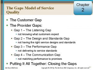
 Gaps model for improving service quality
 Techniques for achieving good quality of service
 Quality taxi service
 What about today's class
 Package mypackage; class first { /* class body */ }
 Introduction to ooad
 How to find mode of grouped data
 Class i vs class ii mhc
 Difference between abstract class and concrete class
 Lower class boundary
 Sd and sdelta
 Stimuli vs stimulus
