CKPSeries J 1939 customizable keypads Product Training Module

CKP-Series J 1939 customizable keypads Product Training Module www. carlingtech. com 860. 793. 9281 sales@carlingtech. com

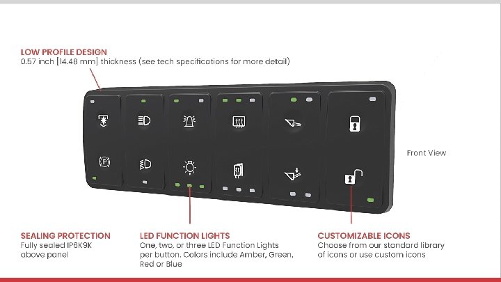
Highlights and Applications Compliant with SAE J 1939 CAN standards, the CKP-Series is a customizable membrane keypad featuring laser etched legends and up to three dimmable LED function lights per button, which also offer diagnostic feedback by blinking if there is a fault. With above and below sealing protection, the CKP-series can be installed inside or outside the cab. • • • SAE J 1939 CAN 2. 0 b Protocol IP 6 k 9 k Above Panel Sealing Protection IP 6 k 8 Below Panel Sealing Protection Low Profile Design Installs Vertically or Horizontally Install Inside or Outside Cab Up to 3 LED Function Lights per Button Standard or Custom Laser Etched Legends Diagnostic Feedback 1, 000 Actuation Cycles Low Current Switching 8 to 32 V Operating Voltage Tactile and Audible Feedback
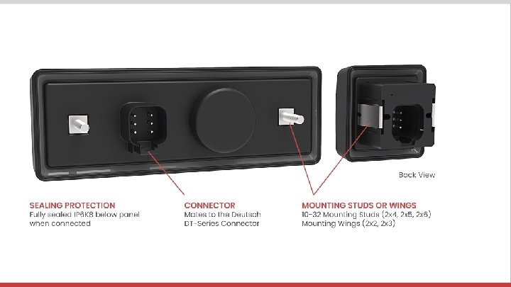

Compared to Electromechanical • 1, 000 Actuation Cycles • Reduced Wire Harnessing • Diagnostics Feedback in Case of Failure • Easy Installation Built in Connector Mates to the Deutsch DT-Series Connector

See Datasheet for Complete Specifications and Details

See Datasheet for Complete Specifications and Details Transient Immunity Transient Emission ISO 11452 -2, 100 V/m, 20 MHz to 2, 000 MHz, ISO 13766, Broadband: Annex D, Class A per ISO 11451 -1 Conducted Transient Immunity ISO 7637 -2: 2004, Annex A Table A 2 (for 24 V systems), Class A EDS Immunity ISO 10605: 2001, Test Level IV (8 k. V direct discharge, 15 k. V air discharge) Narrow band: Annex E, 30 -1000 MHz

What is J 1939? SAE STANDARDS > SAE J 1939 EXPLAINED > Power. Point must be in presentation mode for the links to execute.

J 1939 Interface Specifications > Power. Point must be in presentation mode for the links to execute.
![In. [mm]](http://slidetodoc.com/presentation_image_h/34ec0697c1d1e3c1a75fdd235371d9ad/image-10.jpg "In. [mm]")
In. [mm]
![In. [mm]](http://slidetodoc.com/presentation_image_h/34ec0697c1d1e3c1a75fdd235371d9ad/image-11.jpg "In. [mm]")
In. [mm]

STEP 1 First, configure base of the keypad including orientation & function light color.

STEP 1 Continued | Orientation Options

STEP 2 Second, configure how the 3 light codes per button will function from options 1 -8 and choose the laser etched icon for each of the 12 buttons (2 x 6); 10 buttons (2 x 5); 8 buttons (2 x 4); 6 buttons (2 x 3) or 4 buttons (2 x 2). The black dots, as shown in options 1 -8, are representative of which position will be laser etched to reveal the lights on the PC Board.

& Additional Information

Power. Point must be in presentation mode for the links to execute. Manual Change Source Address >
- Slides: 16