
Cisco Support Community Expert Series Webcast Cisco Optical
Cisco Support Community Expert Series Webcast Cisco Optical Networking – Chromatic Dispersion calculation. Kayukov Valeriy Optical System Engineer Step Logic April 15, 2016
Have you ever had deal with DWDM Cisco ONS devices? Question 1 1. Yes 2. No 3. Cisco have such platforms? © 2015 Cisco and/or its affiliates. All rights reserved. 2
Content of presentation • Chromatic Dispersion • Measurement of CD in real Fiber • Sample of calculation in CTP • Polarization Mode Dispersion © 2015 Cisco and/or its affiliates. All rights reserved. 3
Chromatic Dispersion © 2015 Cisco and/or its affiliates. All rights reserved. 4
Optical Dispersion types: • Chromatic Dispersion (CD) – is based on effect of impulse broadening during passing through optical fiber. • Polarization Mode Dispersion - a temporary difference between the polarization components of the same signal. © 2015 Cisco and/or its affiliates. All rights reserved. 5
Chromatic Dispersion (CD) • Optical pulse time-expanded by passing through the optical fiber. This process triggers limitation of bandwidth throughput or maximum transition distance with constant bandwidth. • Chromatic Dispersion is fiber characteristic with is measured in ps/km*nm and depends on wavelength. • To compensate dispersion used pre-compensation and post-compensation techniques. Dispersion compensators is based on negative dispersion fiber. © 2015 Cisco and/or its affiliates. All rights reserved. 6
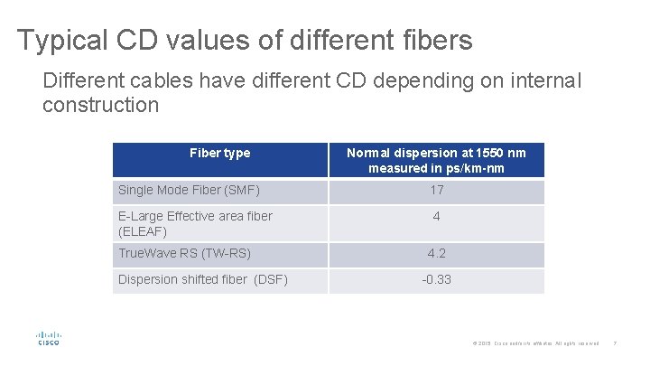
Typical CD values of different fibers Different cables have different CD depending on internal construction Fiber type Normal dispersion at 1550 nm measured in ps/km-nm Single Mode Fiber (SMF) 17 E-Large Effective area fiber (ELEAF) 4 True. Wave RS (TW-RS) Dispersion shifted fiber (DSF) 4. 2 -0. 33 © 2015 Cisco and/or its affiliates. All rights reserved. 7
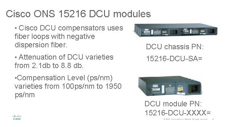
Cisco ONS 15216 DCU modules • Cisco DCU compensators uses fiber loops with negative dispersion fiber. DCU chassis PN: • Attenuation of DCU varieties 15216 -DCU-SA= from 2. 1 db to 8. 8 db. • Compensation Level (ps/nm) varieties from 100 ps/nm to 1950 ps/nm DCU module PN: 15216 -DCU-XXXX= © 2015 Cisco and/or its affiliates. All rights reserved. 8
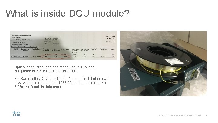
What is inside DCU module? Optical spool produced and measured in Thailand, completed in in hard case in Denmark. For Sample this DCU has 1950 psnm nominal, but in real how we see in report it has 1957, 33 ps/nm. Insertion loss 6. 97 db vs 8. 8 db in data sheet. © 2015 Cisco and/or its affiliates. All rights reserved. 9
Pluses and minuses of use DCU • Disadvantage of use DCU in network is that DC add significant attenuationloss. This is due to difference of coupling transition and fiber used in DCU. • Advantage of use compensators is that DCU limit nonlinear effects. Different dispersion profile result in a phase mismatch, witch prevent from FWM happening. © 2015 Cisco and/or its affiliates. All rights reserved. 10
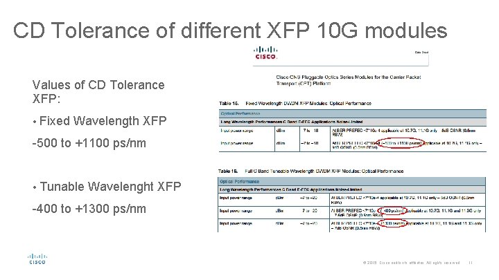
CD Tolerance of different XFP 10 G modules Values of CD Tolerance XFP: • Fixed Wavelength XFP -500 to +1100 ps/nm • Tunable Wavelenght XFP -400 to +1300 ps/nm © 2015 Cisco and/or its affiliates. All rights reserved. 11
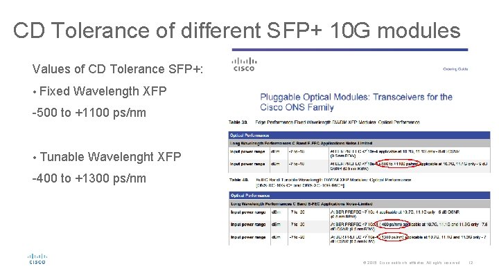
CD Tolerance of different SFP+ 10 G modules Values of CD Tolerance SFP+: • Fixed Wavelength XFP -500 to +1100 ps/nm • Tunable Wavelenght XFP -400 to +1300 ps/nm © 2015 Cisco and/or its affiliates. All rights reserved. 12
Comparison of SFP+ vs XFP modules • Use of fixed wavelength SFP+XFP has disadvantages in case failure. Fixed wavelength could be replaced by tunable module or the SAME wavelength module. • GLP Price Discount could be higher for tunable modules that for fixed. Contact to your Cisco CAM. • In future line DWDM network could be upgraded to colorless or directionless. © 2015 Cisco and/or its affiliates. All rights reserved. 13
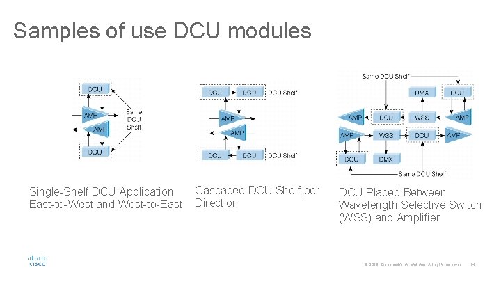
Samples of use DCU modules Single-Shelf DCU Application East-to-West and West-to-East Cascaded DCU Shelf per Direction DCU Placed Between Wavelength Selective Switch (WSS) and Amplifier © 2015 Cisco and/or its affiliates. All rights reserved. 14
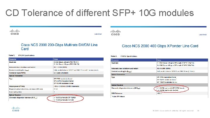
CD Tolerance of different SFP+ 10 G modules © 2015 Cisco and/or its affiliates. All rights reserved. 15
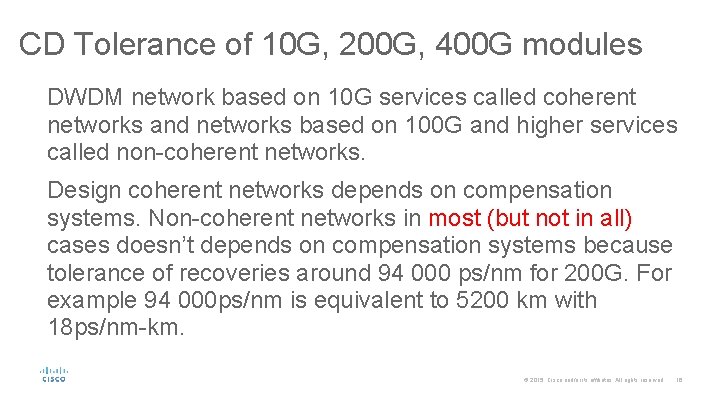
CD Tolerance of 10 G, 200 G, 400 G modules DWDM network based on 10 G services called coherent networks and networks based on 100 G and higher services called non-coherent networks. Design coherent networks depends on compensation systems. Non-coherent networks in most (but not in all) cases doesn’t depends on compensation systems because tolerance of recoveries around 94 000 ps/nm for 200 G. For example 94 000 ps/nm is equivalent to 5200 km with 18 ps/nm-km. © 2015 Cisco and/or its affiliates. All rights reserved. 16

Measurement of CD of real fiber © 2015 Cisco and/or its affiliates. All rights reserved. 17
CD measurement, Introduction What parameters are measured: • dispersion coefficient values measured at specified wavelength • dispersion maximum over specified range of wavelengths • zero dispersion wavelength and dispersion slope at this wavelength © 2015 Cisco and/or its affiliates. All rights reserved. 18
Measurement methods (Phase Shift vs Pulse Delay ) Both methods measure propagation delay (or group delay) at selected wavelength and, from the measured delay versus wavelength data, interpolate the delay for other wavelength not directly measured by using numerical fitting algorithms. • Phase Shift – method of comparison of test signal and reference signal used to modulate the input signal. The phase difference is performed versus wavelength over the entire wavelength range of source. • Pulse Delay - © 2015 Cisco and/or its affiliates. All rights reserved. 19
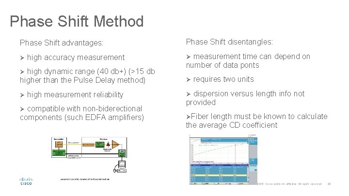
Phase Shift Method Phase Shift advantages: Phase Shift disentangles: Ø high accuracy measurement Ø measurement time can depend on Ø high dynamic range (40 db+) (>15 db number of data ponts higher than the Pulse Delay method) Ø requires two units Ø high measurement reliability Ø dispersion versus length info not Ø compatible with non-biderectional components (such EDFA amplifiers) provided ØFiber length must be known to calculate the average CD coefficient © 2015 Cisco and/or its affiliates. All rights reserved. 20
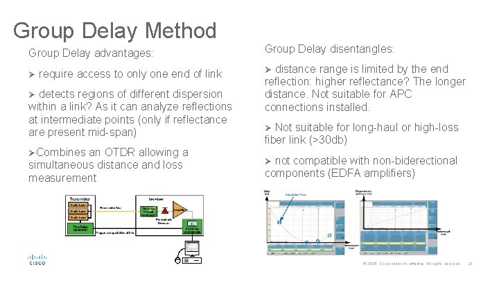
Group Delay Method Group Delay advantages: Ø require access to only one end of link Ø detects regions of different dispersion within a link? As it can analyze reflections at intermediate points (only if reflectance are present mid-span) ØCombines an OTDR allowing a simultaneous distance and loss measurement Group Delay disentangles: Ø distance range is limited by the end reflection: higher reflectance? The longer distance. Not suitable for APC connections installed. Ø Not suitable for long-haul or high-loss fiber link (>30 db) Ø not compatible with non-biderectional components (EDFA amplifiers) © 2015 Cisco and/or its affiliates. All rights reserved. 21
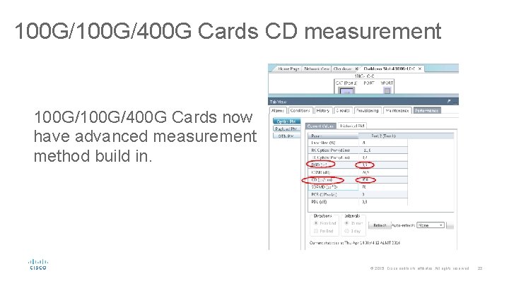
100 G/400 G Cards CD measurement 100 G/400 G Cards now have advanced measurement method build in. © 2015 Cisco and/or its affiliates. All rights reserved. 22
Sample of calculation in CTP, XLS © 2015 Cisco and/or its affiliates. All rights reserved. 23
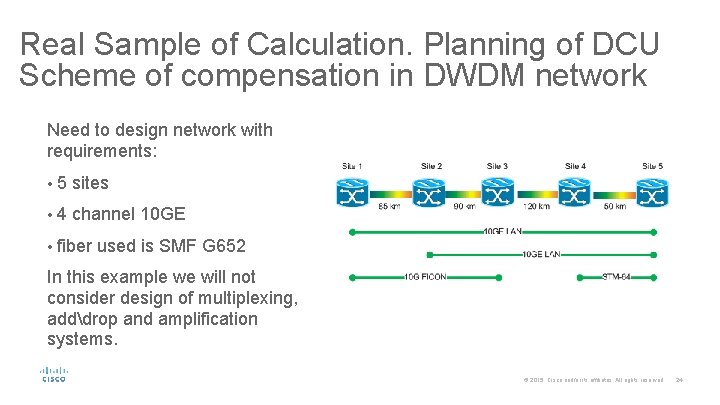
Real Sample of Calculation. Planning of DCU Scheme of compensation in DWDM network Need to design network with requirements: • 5 sites • 4 channel 10 GE • fiber used is SMF G 652 In this example we will not consider design of multiplexing, adddrop and amplification systems. © 2015 Cisco and/or its affiliates. All rights reserved. 24
Lets start to work in CTP. Step 1 – Preparation. In this step we will make: • Start – “Project Creation Wizard” • Start – “Run the Network Wizard Now” • Create circuit – “Create Net Point-to-Point Demand” • Start – “Network Analyze” • Go to – “Summary” –> “Optical Reports” © 2015 Cisco and/or its affiliates. All rights reserved. 25
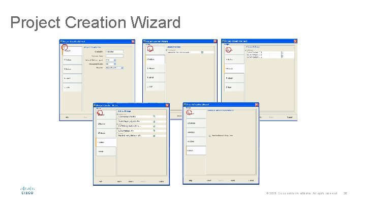
Project Creation Wizard © 2015 Cisco and/or its affiliates. All rights reserved. 26
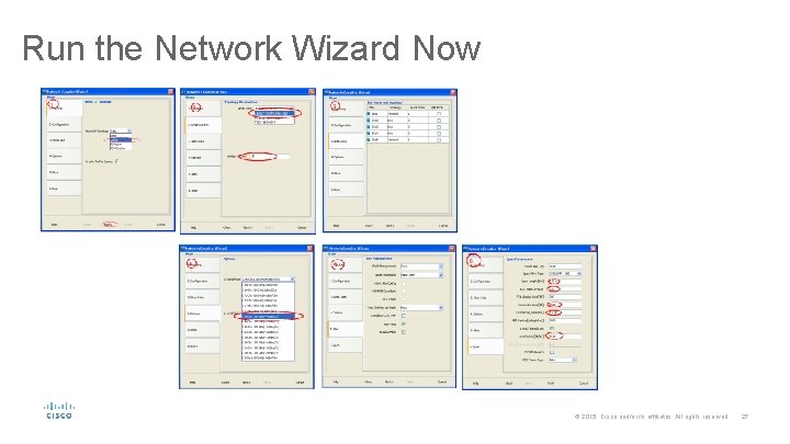
Run the Network Wizard Now © 2015 Cisco and/or its affiliates. All rights reserved. 27
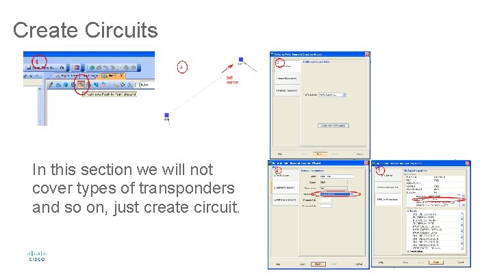
Create Circuits In this section we will not cover types of transponders and so on, just create circuit. © 2015 Cisco and/or its affiliates. All rights reserved. 28
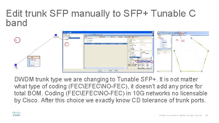
Edit trunk SFP manually to SFP+ Tunable C band DWDM trunk type we are changing to Tunable SFP+. It is not matter what type of coding (FECEFECNO-FEC), it doesn’t add any price for total BOM. Coding (FECEFECNO-FEC) in 10 G networks no licensable by Cisco. After this choice we exactly know CD tolerance of trunk ports. © 2015 Cisco and/or its affiliates. All rights reserved. 29
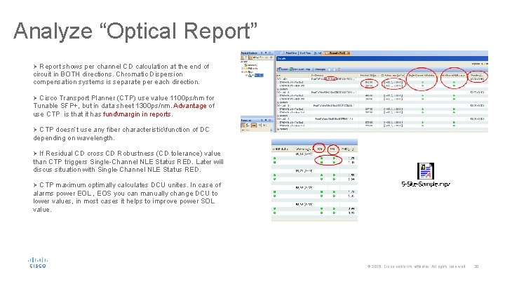
Analyze “Optical Report” Ø Report shows per channel CD calculation at the end of circuit in BOTH directions. Chromatic Dispersion compensation systems is separate per each direction. Ø Cisco Transport Planner (CTP) use value 1100 ps/nm for Tunable SFP+, but in data sheet 1300 ps/nm. Advantage of use CTP is that it has fundmargin in reports. Ø CTP doesn’t use any fiber characteristicfunction of DC depending on wavelength. Ø If Residual CD cross CD Robustness (CD tolerance) value than CTP triggers Single-Channel NLE Status RED. Later will discus situation with Single-Channel NLE Status RED. Ø CTP maximum optimally calculates DCU unites. In case of alarms power EOL , EOS you can manually change DCU to lower values, in most cases it helps to improve power SOL value. © 2015 Cisco and/or its affiliates. All rights reserved. 30
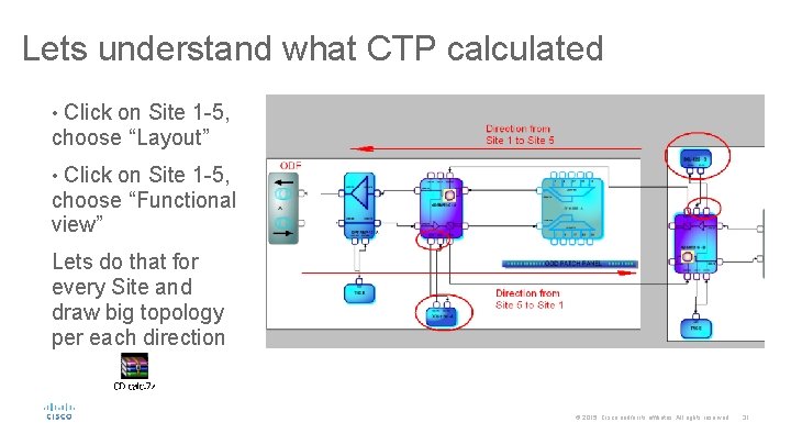
Lets understand what CTP calculated • Click on Site 1 -5, choose “Layout” • Click on Site 1 -5, choose “Functional view” Lets do that for every Site and draw big topology per each direction © 2015 Cisco and/or its affiliates. All rights reserved. 31
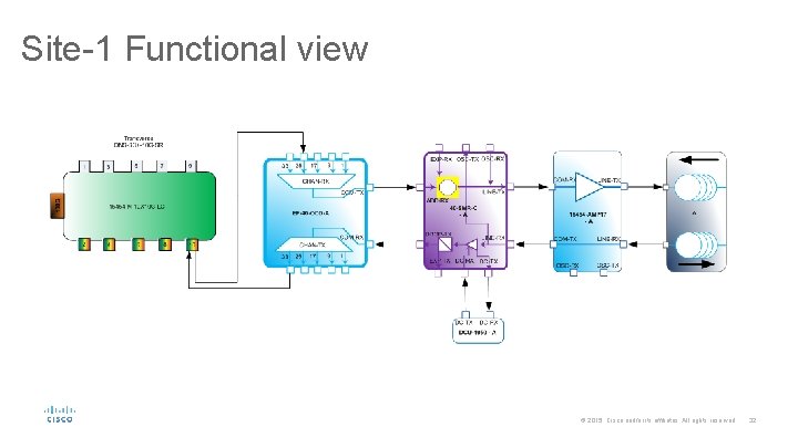
Site-1 Functional view © 2015 Cisco and/or its affiliates. All rights reserved. 32
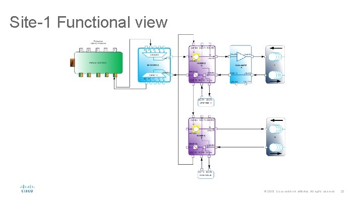
Site-1 Functional view © 2015 Cisco and/or its affiliates. All rights reserved. 33
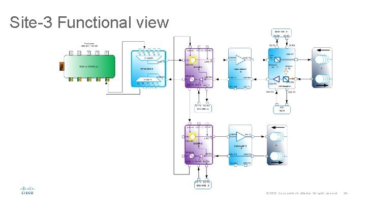
Site-3 Functional view © 2015 Cisco and/or its affiliates. All rights reserved. 34
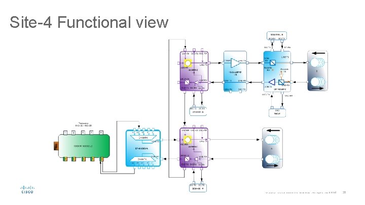
Site-4 Functional view © 2015 Cisco and/or its affiliates. All rights reserved. 35
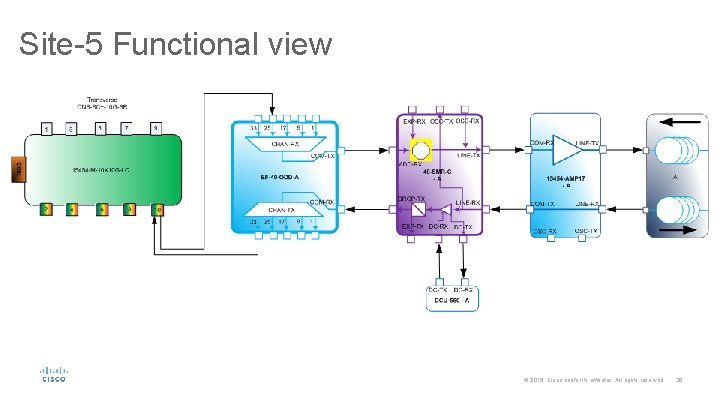
Site-5 Functional view © 2015 Cisco and/or its affiliates. All rights reserved. 36
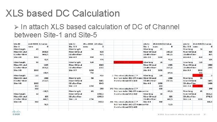
XLS based DC Calculation Ø In attach XLS based calculation of DC of Channel between Site-1 and Site-5 © 2015 Cisco and/or its affiliates. All rights reserved. 37
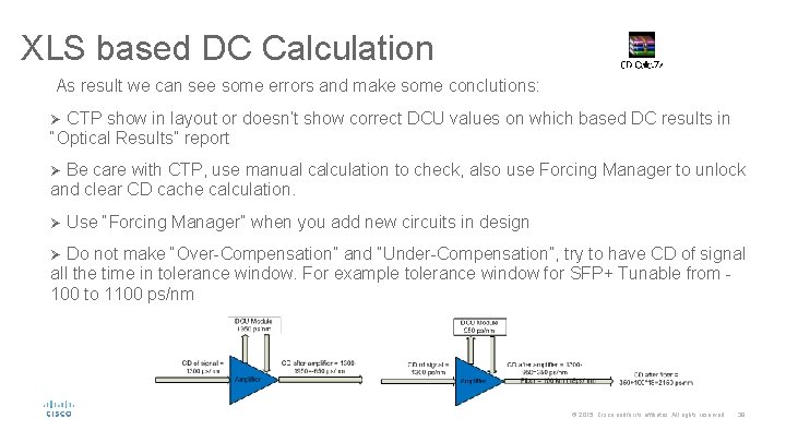
XLS based DC Calculation As result we can see some errors and make some conclutions: Ø CTP show in layout or doesn’t show correct DCU values on which based DC results in “Optical Results” report Ø Be care with CTP, use manual calculation to check, also use Forcing Manager to unlock and clear CD cache calculation. Ø Use “Forcing Manager” when you add new circuits in design Ø Do not make “Over-Compensation” and “Under-Compensation”, try to have CD of signal all the time in tolerance window. For example tolerance window for SFP+ Tunable from 100 to 1100 ps/nm © 2015 Cisco and/or its affiliates. All rights reserved. 38
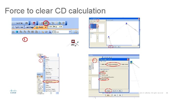
Force to clear CD calculation © 2015 Cisco and/or its affiliates. All rights reserved. 39
Polarization Mode Dispersion © 2015 Cisco and/or its affiliates. All rights reserved. 40
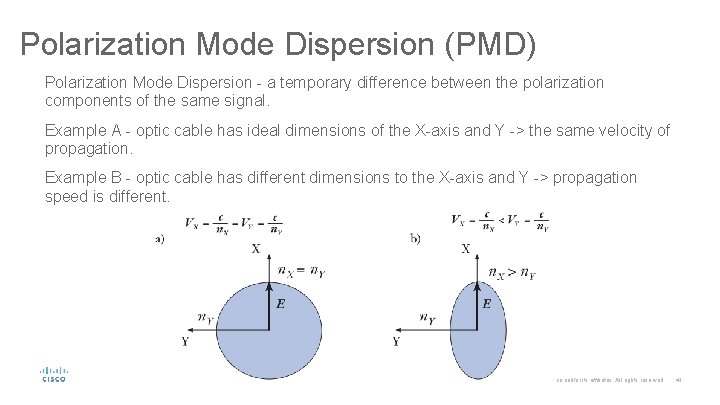
Polarization Mode Dispersion (PMD) Polarization Mode Dispersion - a temporary difference between the polarization components of the same signal. Example A - optic cable has ideal dimensions of the X-axis and Y -> the same velocity of propagation. Example B - optic cable has different dimensions to the X-axis and Y -> propagation speed is different. © 2015 Cisco and/or its affiliates. All rights reserved. 41
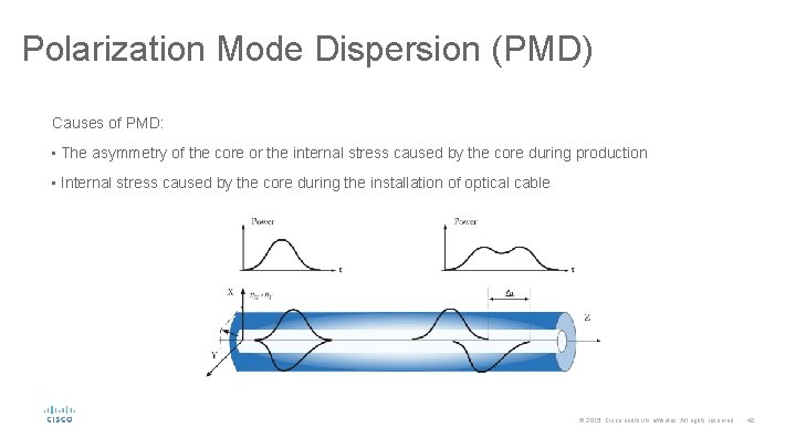
Polarization Mode Dispersion (PMD) Causes of PMD: • The asymmetry of the core or the internal stress caused by the core during production • Internal stress caused by the core during the installation of optical cable © 2015 Cisco and/or its affiliates. All rights reserved. 42

- Slides: 43