CIS 3360 Security in Computing PreKnowledge Internet and


: millions of connected computing devices")


 ISPs q Connect")


: q q client/server model q q q")
![Network edge: connection-oriented service TCP [ Transmission Control Protocol ] q reliable, in-order :](https://slidetodoc.com/presentation_image_h/8fe5e8108342981b826e18d05e6a4f52/image-24.jpg "Network edge: connection-oriented service TCP [ Transmission Control Protocol ] q reliable, in-order :")
![Network edge: connectionless service q UDP [User Datagram Protocol] connectionless q unreliable data transfer](https://slidetodoc.com/presentation_image_h/8fe5e8108342981b826e18d05e6a4f52/image-25.jpg "Network edge: connectionless service q UDP [User Datagram Protocol] connectionless q unreliable data transfer")


 Internet")


 Need sequence # and acknowledge # to")
 32 bits URG: urgent data (generally")


 Host A Host B Send. Base = 120 Seq= es")


 client Closing a connection: close(); close server FIN Step")
 client Step 3: client receives FIN, replies with ACK.")
- Slides: 51
CIS 3360: Security in Computing Pre-Knowledge: Internet and Networking Cliff Zou Spring 2012
Objectives q Obtain the basic knowledge of computer networking and the Internet q q q Concepts of network applications, Internet Basic knowledge of network protocols: TCP/IP Reading assignment: q Wikipiedia tutorials: http: //en. wikipedia. org/wiki/Internet q http: //en. wikipedia. org/wiki/TCP/IP q q Reference book: q Computer Networking: A Top Down Approach Featuring the Internet, 5 th edition. Jim Kurose, Keith Ross, Addison-Wesley, Pearson Education, 2010 2
Lecture Materials Some of these slides are adapted from the slides copyrighted by Jim Kurose, Keith Ross Addison-Wesley, Pearson Education 2010. Computer Networking: A Top Down Approach Featuring the Internet, 5 th edition. 3
A Little Bit of Internet History q q q 1961: Kleinrock - queueing theory shows effectiveness of packetswitching 1967: ARPAnet conceived by Advanced Research Projects Agency 1969: First ARPAnet node operational 1972: 15 nodes in ARPAnet; First e-mail program 1973: Metcalfe’s Ph. D thesis proposes Ethernet 1974: Cerf and Kahn - architecture for interconnecting networks 1983: deployment of TCP/IP 1982: smtp e-mail protocol defined 1983: DNS defined for name-to-IP-address translation early 1990 s: Web Late 1990’s – 2000’s: instant messaging, P 2 P file sharing; network security, est. 50 million host, 100 million+ users, backbone links running at Gbps 4
Cerf and Kahn’s internetworking principles: q minimalism, autonomy - no internal changes required to interconnect networks q best effort service model q stateless routers q decentralized control define today’s Internet architecture 5
What is the Internet? Application Web, Email… Application Transport TCP, UDP Transport Network IP Network Data Link Ethernet, cellular Data Link Physical 6 link
Some Internet applications q q q q E-mail Web Instant messaging Remote login P 2 P file sharing Multi-user network games Streaming stored video clips q q q Internet telephone Real-time video conference Massive parallel computing
Internet q Internet: loosely hierarchical “network of networks” q q Major Components: Hosts, Routers, Communication links Protocols: for sending, receiving of msgs q e. g. , TCP, IP, HTTP, FTP, PPP q Internet standards q q RFC: Request for comments IETF: Internet Engineering Task Force router server workstation mobile local ISP regional ISP company network 8 8
Internet: Three Components q q q End systems (hosts): millions of connected computing devices executing network applications Routers: forwarding packets (chunks of data) Communication links: Connecting hosts and routers q q fiber, copper, radio, satellite transmission rate = bandwidth router server workstation mobile local ISP regional ISP company network 9 9
Internet Service q Communication infrastructure enables distributed applications: q q Web, email, games, e-commerce, file sharing Communication services provided to applications: q q Connectionless unreliable connection-oriented reliable 10 10
Internet structure: network of networks q q roughly hierarchical at center: “tier-1” ISPs (e. g. , UUNet, BBN/Genuity, Sprint, AT&T), national/international coverage q treat each other as equals Tier-1 providers interconnect (peer) privately Tier 1 ISP NAP Tier-1 providers also interconnect at public network access points (NAPs) Tier 1 ISP 11 11
Internet structure: network of networks q “Tier-2” ISPs: smaller (often regional) ISPs q Connect to one or more tier-1 ISPs, possibly other tier-2 ISPs Tier-2 ISP pays tier-1 ISP for connectivity to rest of Internet q tier-2 ISP is customer of tier-1 provider Tier-2 ISP Tier 1 ISP Tier-2 ISP NAP Tier 1 ISP Tier-2 ISPs also peer privately with each other, interconnect at NAP Tier-2 ISP 12 12
Internet structure: network of networks q “Tier-3” ISPs and local ISPs q last hop (“access”) network (closest to end systems) local ISP Local and tier - 3 ISPs are customers of higher tier ISPs connecting them to rest of Internet Tier 3 ISP Tier-2 ISP local ISP Tier-2 ISP Tier 1 ISP Tier-2 ISP local ISP NAP Tier 1 ISP Tier-2 ISP local ISP 13 13
Internet structure: network of networks q a packet passes through many networks! local ISP Tier 3 ISP Tier-2 ISP local ISP Tier-2 ISP Tier 1 ISP Tier-2 ISP local ISP NAP Tier 1 ISP Tier-2 ISP local ISP 14 14
“Real” Internet delays and routes q q What do “real” Internet delay & loss look like? Traceroute program: provides delay measurement from source to router along end-end Internet path towards destination. For all i: q q q sends three packets that will reach router i on path towards destination router i will return packets to sender times interval between transmission and reply. 3 probes
“Real” Internet delays and routes traceroute: gaia. cs. umass. edu to www. eurecom. fr Three delay measurements from gaia. cs. umass. edu to cs 1 cs-gw (128. 119. 240. 254) 1 ms 2 ms gw. cs. umass. edu 2 border 1 -rt-fa 5 -1 -0. gw. umass. edu (128. 119. 3. 145) 1 ms 2 ms 3 cht-vbns. gw. umass. edu (128. 119. 3. 130) 6 ms 5 ms 4 jn 1 -at 1 -0 -0 -19. wor. vbns. net (204. 147. 132. 129) 16 ms 11 ms 13 ms 5 jn 1 -so 7 -0 -0 -0. wae. vbns. net (204. 147. 136) 21 ms 18 ms 6 abilene-vbns. abilene. ucaid. edu (198. 32. 11. 9) 22 ms 18 ms 22 ms 7 nycm-wash. abilene. ucaid. edu (198. 32. 8. 46) 22 mstrans-oceanic 8 62. 40. 103. 253 (62. 40. 103. 253) 104 ms 109 ms 106 ms link 9 de 2 -1. de. geant. net (62. 40. 96. 129) 109 ms 102 ms 104 ms 10 de. fr 1. fr. geant. net (62. 40. 96. 50) 113 ms 121 ms 114 ms 11 renater-gw. fr 1. fr. geant. net (62. 40. 103. 54) 112 ms 114 ms 112 ms 12 nio-n 2. cssi. renater. fr (193. 51. 206. 13) 111 ms 114 ms 116 ms 13 nice. cssi. renater. fr (195. 220. 98. 102) 123 ms 125 ms 124 ms 14 r 3 t 2 -nice. cssi. renater. fr (195. 220. 98. 110) 126 ms 124 ms 15 eurecom-valbonne. r 3 t 2. ft. net (193. 48. 50. 54) 135 ms 128 ms 133 ms 16 194. 211. 25 (194. 211. 25) 126 ms 128 ms 126 ms 17 * * means no response (probe lost, router not replying) 18 * * * 19 fantasia. eurecom. fr (193. 55. 113. 142) 132 ms 128 ms 136 ms Under Windows is “tracert”
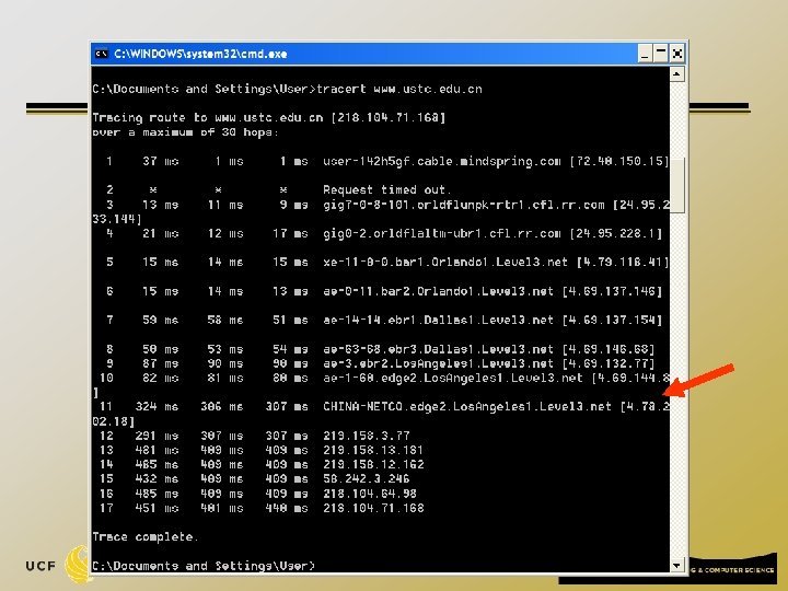
Traceroute from My Home Computer
Where a Router is Placed? q There are many public websites provide IP location service www. geobytes. com/iplocator. htm q http: //www. iplocation. net/ q q Based on traceroute and IP locator, you can know the complete routing path of a connection q Major reason why many networks block traceroute traffic 19
Protocol network protocols: q all communication activity in Internet governed by protocols Protocols define format, order of messages sent and received among network entities, and actions taken on message transmission, receipt
What’s a protocol? a human protocol and a computer network protocol: Hi TCP connection request Hi TCP connection response Got the time? Get http: //www. awl. com/kurose-ross 2: 00 <file> time
A closer look at network structure: q q network edge: applications and hosts network core: routers q network of networks q q Connection: communication links 22 22
The network edge: q end systems (hosts): q q client/server model q q q run application programs e. g. Web, email at “edge of network” client host requests, receives service from always-on server e. g. Web browser/server; email client/server peer-peer model: q q minimal (or no) use of dedicated servers e. g. Gnutella, Ka. Za. A
Network edge: connection-oriented service TCP [ Transmission Control Protocol ] q reliable, in-order : byte-stream data transfer q q flow control: q q loss: acknowledgements and retransmissions sender won’t overwhelm receiver congestion control: q senders “slow down sending rate” when network congested Examples of applications using TCP: q HTTP (Web), FTP (file transfer), SSH (remote secure login), SMTP (email)
Network edge: connectionless service q UDP [User Datagram Protocol] connectionless q unreliable data transfer q no flow control q no congestion control q Examples of applications using UDP: q streaming media, teleconferencing, DNS, Internet telephony
The Network Core q q mesh of interconnected routers data transfer methods through net circuit switching: dedicated circuit per call: telephone net q packet-switching: data sent through net in discrete “chunks” q
Circuit Switching End-end resources reserved for “call” q q call setup required link bandwidth, switch capacity dedicated resources: no sharing circuit-like (guaranteed) performance
Packet-switched networks q q Move packets through routers from source to destination datagram network: q q q destination address in packet determines next hop routes may change during session virtual circuit network: q q q each packet carries tag (virtual circuit ID), tag determines next hop fixed path determined at call setup time, remains fixed thru call routers maintain per-call state
Internet protocol stack q application: supporting network applications q q transport: host-host data transfer q q IP, routing protocols link: data transfer between neighboring network elements q q TCP, UDP network: routing of datagrams from source to destination q q FTP, SMTP, HTTP PPP, Ethernet physical: bits “on the wire or wireless” application transport network link physical
source message segment Ht datagram Hn Ht frame Hl Hn Ht M M application transport network link physical Encapsulation Hl Hn Ht M link physical Hl Hn Ht M switch destination M Ht M Hn Ht Hl Hn Ht M M application transport network link physical Hn Ht Hl Hn Ht M M router
Message Flow q q q transport segment from sending to receiving host on sending side encapsulates segments into datagrams on receiving side, delivers segments to transport layer network layer protocols in every host, router examines header fields in all IP datagrams passing through it application transport network data link physical network data link physical network data link physical application transport network data link physical 31
TCP/IP Introduction 32
q TCP Transport Layer q IP Network Layer q Networking security mainly deals with these two services/protocols 33
Transport Layer q TCP - connection-oriented service q q Provide reliable data transmission Used by most data-based, not time-sensitive network applications q q q Email, Web, file transfer…. Require to set up TCP connection channel first UDP – connectionless service q q Unreliable data transmission Error packets will be discarded without retransmission q q No additional delay for future incoming packets Used for time-sensitive, error-tolerant applications q VOIP, video streaming, DNS…. 34
Transport vs. network layer q q network layer: logical communication between hosts transport layer: logical communication between processes q relies on, enhances, network layer services C Sport: 8050 Dport: 25 A B Sport: 4625 Dport: 80 D
Addressing processes q q q to receive messages, process must have identifier includes both IP address and port numbers associated with process on host device has unique 32 -bit IP address q q Example port numbers: q q q IP address is for addressing a host/computer HTTP server: 80 Mail server: 25 to send HTTP message to gaia. cs. umass. edu web server: q q IP address: 128. 119. 245. 12 Port number: 80
TCP and UDP Port Numbers q q q 16 bits (0 – 65535) Internet Assigned Numbers Authority (IANA) www. iana. org Well known ports (0 -1023) q q Registered ports (1024 – 49151) q q Example: HTTP – 80, SMTP – 25 Example: HTTP alternate 8080 used for web proxy and caching server Dynamic and/or private ports: (49152– 65535)
q Each TCP connection is identified by 4 -tuple: source IP address q source port number q dest IP address q dest port number q q These four values are widely used in network filtering and intrusion detection 38
UDP Packet Header q q q UDP packet Length, in header is 8 bytes of UDP segment, bytes long including header Port number is 16 bits long Checksum for verifying packet error 39 32 bits source port # dest port # length checksum Application data (message) UDP segment format
UDP Transmission Process Host B Host A q q Packe t 1 No acknowledgement from recipient Sending rate is controlled by sender (bounded by sender’s bandwidth) Pack et 2 Pack et 3 Pack et 4 Pack et 5 time 40 X
TCP Transmission Process (simplified without considering piplining) Need sequence # and acknowledge # to distinguish each packet 41
TCP segment structure (Header is 20 bytes normally) 32 bits URG: urgent data (generally not used) ACK: ACK # valid PSH: push data now RST, SYN, FIN: connection estab (setup, teardown commands) Internet checksum (as in UDP) source port # dest port # sequence number acknowledgement number head not UA P R S F len used checksum Receive window Urg data pnter Options (variable length) application data (variable length) counting by bytes of data (not segments!) # bytes rcvr willing to accept
TCP seq. #’s and ACKs Seq. #’s: q byte stream “number” of first byte in segment’s data ACKs: q seq # of next byte expected from other side q Cumulative ack to receive all bytes until the specified # Q: how receiver handles out-of-order segments? q q TCP spec doesn’t say Practical approach: save in buffer Q: How TCP implement duplex communication? q Seq. # for sending data, Ack# for receiving data
An example of TCP Duplex Communication Host B Host A User 42 Seq=4 2, ACK =79, d 7 Seq= host ACKs receipt, send back use password Sequence number is based on bytes, not packets! ata = ‘ =46, K C 9, A Seq=4 79 6, ACK john’ host ACKs receipt, echoes ’ s s a p ‘ back ‘pass’ = ata d =83 da ta =‘C NT 470 4’ simple telnet scenario time
ACK Only in Duplex Communication ? K=46 C A 79, Seq= host ACKs receipt, send back use password Seq=4 ’ pass ‘ = a , dat 6, ACK 3 8 = q e S =83 da , =53, K C A ta =‘C NT 470 4’ n ta se o da ction time ACK only packet, seq# is the first byte to be transmitted in the future (the packet has no data section) 45
TCP: retransmission scenarios Host A tes da ta 00 X =1 ACK loss Seq=9 2, 8 by tes da ta 100 Sendbase = 100 Send. Base = 120 = ACK Send. Base = 100 time Host B Seq=92 timeout 2, 8 by Send. Base = 120 lost ACK scenario Seq= 2, 8 by t es dat a 100, 2 0 byt es da ta 0 10 = K 120 = C K A AC Seq=9 2, 8 by Seq=92 timeout Seq=9 timeout Host A Host B time tes da ta 120 = CK A premature timeout
TCP retransmission scenarios (more) Host A Host B Send. Base = 120 Seq= es da t a 0 10 = K 120 = C K A AC 2, 8 by time 2, 8 by ta 0 byt tes da ta Host B Seq=9 tes da 100, 2 Seq=92 timeout Sendbase = 100 Send. Base = 120 2, 8 by timeout Seq=92 timeout Seq=9 Host A Send. Base = 120 tes da ta 100 = K AC bytes data Seq=1 00, 20 X loss 20 =1 ACK 0 12 K= AC premature timeout time Cumulative ACK scenario
TCP Connection Setup --Three-Way Handshaking Step 1: client host sends TCP SYN segment to server m specifies initial seq # m no data Step 2: server host receives SYN, replies with SYN/ACK segment server allocates buffers m specifies server initial seq. # Step 3: client receives SYN/ACK, replies with ACK segment, which may contain data m client server SY seq=c N, lient_s eq CK, q, A / N e SY er_s +1 v r e s q seq= lient_se c ack= ACK, seq=c li ack=s ent_seq+1 erver_ seq+1
TCP Connection Setup q Most firewalls, packet capturing software, and intrusion detection software use TCP connection setup packets to determine how to deal with the new connection q Very important to understand the three-way handshake 49
TCP Connection Management (cont. ) client Closing a connection: close(); close server FIN Step 1: client end system sends TCP/FIN control segment to server replies with ACK. Closes connection, sends FIN timed wait Step 2: server receives FIN, ACK closed ACK close
TCP Connection Management (cont. ) client Step 3: client receives FIN, replies with ACK. q closing Enters “timed wait” - will respond with ACK to received FINs server FIN ACK closing FIN Step 4: server, receives ACK. Some applications simply send RST to terminate TCP connections immediately timed wait Connection closed ACK closed