Circuit Switches The Telephone Network Signaling Traffic and


nk + k (N/n)2 crosspoints n k 1 N inputs N/n")

 Switching l l l c … 23 l. Incoming TDM stream")


 C 2 A (b) l 4 D 3 1 5 B")

 l l First effort to provide end-to-end digital connections")


 l Crossbar switches with crossbars")

 #7 deployed in 1970 s to")


 All trunks busy, new")
 the number of calls in")


- Slides: 51
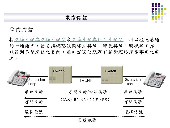
Circuit Switches The Telephone Network Signaling Traffic and Overload Control in Telephone Networks 學號:M 9308383 座號: 9 姓名:盧相平 指導教授:陳明仕 教授 2005. 04. 27.
Chapter 4 Circuit-Switching Networks Circuit Switches
Network: Links & switches l l Circuit consists of dedicated resources in sequence of links & switches across network Circuit switch connects input links to output links l. Switch l. Network Switch User n 1 2 3 … User n – 1 User 1 N Connection of inputs to outputs 1 2 3 … Link Control N
Circuit Switch Types l Space-Division switches l l Time-Division switches l l l Provide separate physical connection between inputs and outputs Crossbar switches Multistage switches Time-slot interchange technique Time-space-time switches Hybrids combine Time & Space switching
Crossbar Space Switch l l l N x N array of crosspoints Connect an input to an output by closing a crosspoint Nonblocking: Any input can connect to idle output Complexity: N 2 crosspoints 1 2 … l N 1 2 … N – 1 N
Multistage Space Switch 2(N/n)nk + k (N/n)2 crosspoints n k 1 N inputs N/n 1 n k N/n 2 3 2 k n 3 k n n k N/n 1 k n n k 2 k n … l Large switch built from multiple stages of small switches The n inputs to a first-stage switch share k paths through intermediate crossbar switches Larger k (more intermediate switches) means more paths to output … l N/n k N/n N outputs
Clos Non-Blocking Condition: k=2 n-1 l Request connection from last input to input switch j to last output in output switch m l Worst Case: All other inputs have seized top n-1 middle switches AND all other outputs have seized next n-1 middle switches l If k=2 n-1, there is another path left to connect desired input to desired output nxk … j 1 1 n-1 busy … … 1 Desired input kxn N/n x N/n n-1 N/n x N/n n+1 kxn m n-1 busy … nxk N/n x N/n 2 n-2 nxk N/n Free path N/n x N/n 2 n-1 Free path kxn N/n Desired output # internal links = 2 x # external links
Time-Slot Interchange (TSI) Switching l l l c … 23 l. Incoming TDM stream 1 a 2 b 3 b 2 a 1 Write 22 slots in order of 23 arrival 24 d 24 Write bytes from arriving TDM stream into memory Read bytes in permuted order into outgoing TDM stream Max # slots = 125 msec / (2 x memory cycle time) Read slots according to connection permutation c d Time-slot interchange b 24 a … 23 l. Outgoing TDM stream d 2 c 1
Time-Space-Time Hybrid Switch l Use TSI in first & third stage; Use crossbar in middle Replace n input x k output space switch by TSI switch that takes n-slot input frame and switches it to k-slot output frame nxk 1 N inputs kxn N/n x N/n 1 1 nxk 2 n … 2 1 nxk 1 2 3 Input TDM frame with n slots … l n N/n Time-slot interchange Output TDM frame with k slots k … 2 1
Flow of time slots between switches First slot N/n n k 1 k n 1 1 k n n k 2 2 N/n … … k n n k N/n N/n kth slot l … 2 k kth slot Only one space switch active in each time slot
Time-Share the Crossbar Switch Space stage TSI stage TDM n slots nxk 1 2 N inputs n slots nxk l l kxn 1 kxn N/n x N/n Time-shared space switch 2 kxn N outputs 3 … n slots TDM k slots … 3 TSI stage nxk kxn N/n Interconnection pattern of space switch is reconfigured every time slot Very compact design: fewer lines because of TDM & less space because of time-shared crossbar
Example: T-S-T Switch Design For N = 960 l Single stage space switch ~ 1 million crosspoints l T-S-T l l Let n = 120 N/n = 8 TSIs k = 2 n – 1 = 239 for non-blocking Pick k = 240 time slots Need 8 x 8 time-multiplexed space switch For N = 96, 000 l T-S-T l l l Let n = 120 k = 239 N / n = 800 Need 800 x 800 space switch
Pure Optical Switching l l Pure Optical switching: light-in, light-out, without optical-to-electronic conversion Space switching theory can be used to design optical switches l l Multistage designs using small optical switches Typically 2 x 2 or 4 x 4 MEMs and Electro-optic switching devices Wavelength switches l Very interesting designs when space switching is combined with wavelength conversion devices
Chapter 4 Circuit-Switching Networks The Telephone Network
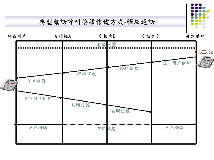
Telephone Call l l Source Signal Destination User requests connection Network signaling establishes connection Speakers converse User(s) hang up Network releases connection resources Go ahead Signal Message Release
Call Routing (a) C 2 A (b) l 4 D 3 1 5 B l Net 1 Net 2 LATA 1 LATA 2 Local calls routed through local network (In U. S. Local Access & Transport Area) Long distance calls routed to long distance service provider
Telephone Local Loop: “Last Mile” l Copper pair from telephone to CO l Pedestal to SAI to Main Distribution Frame (MDF) l 2700 cable pairs in a feeder cable l MDF connects Pedestal l l Serving area interface Distribution frame Local telephone office Distribution cable Serving area interface voice signal to telephone switch DSL signal to routers Switch Feeder cable l. For interesting pictures of switches & MDF, see lweb. mit. edu/is/is/delivery/5 ess/photos. html www. museumofcommunications. org/coe. html
Integrated Services Digital Network (ISDN) l l First effort to provide end-to-end digital connections B channel = 64 kbps, D channel = 16 kbps ISDN defined interface to network Network consisted of separate networks for voice, data, signaling Circuitswitched network BRI Private channelswitched network Packetswitched networks Signaling network Basic rate interface (BRI): 2 B+D BRI Primary rate interface (PRI): 23 B+D
電話網路組織階層圖 Packet. Star TM Voice Gateway 台北長途局 Packet. Star TM Voice Gateway 台中長途局 Packet. Star TM Voice Gateway Packet. Star 彙接局甲 TM 高雄長途局 Voice Gateway Packet. Star 彙接局乙 用戶甲 用戶乙 Voice Gateway 彙接局丙 市話局乙 市話局甲 TM 市話局丙 用戶丙
Chapter 4 Circuit-Switching Networks Signaling
Setting Up Connections Manually l Human Intervention l Telephone l l l Voice commands & switchboard operators Transport Networks l Automatically l Management Interface Order forms & dispatching of craftpersons l Operator at console sets up connections at various switches Automatic signaling l Request for connection generates signaling messages that control connection setup in switches
Stored-Program Control Switches l l SPC switches (1960 s) l Crossbar switches with crossbars built from relays that open/close mechanically through electrical control l Computer program controls set up opening/closing of crosspoints to establish connections between switch inputs and outputs Signaling required to coordinate path set up across network SPC Control Signaling Message
Message Signaling l l l Processors that control switches exchange signaling messages Protocols defining messages & actions defined Modems developed to communicate digitally over converted voice trunks Office A Office B Trunks Switch Processor Switch Modem Signaling Modem Processor
Signaling Network l l Common Channel Signaling (CCS) #7 deployed in 1970 s to control call setup Protocol stack developed to support signaling Signaling network based on highly reliable packet switching network Processors & databases attached to signaling network enabled many new services: caller id, call forwarding, call waiting, user mobility Access Signaling Dial tone SSP Internodal Signaling System 7 STP STP Signaling Network Transport Network SSP = service switching point (signal to message) STP = signal transfer point (packet switch) SCP = service control point (processing) SCP SSP
Signaling System Protocol Stack l Application layer Presentation layer TUP TCAP ISUP l Session layer Transport layer Network layer SCCP l MTP level 3 l Data link layer MTP level 2 l Physical layer ISUP = ISDN user part SSCP = signaling connection control part TUP = telephone user part MTP level 1 Lower 3 layers ensure delivery of messages to signaling nodes SCCP allows messages to be directed to applications TCAP defines messages & protocols between applications ISUP performs basic call setup & release TUP instead of ISUP in some countries MTP = message transfer part TCAP = transaction capabilities part
Future Signaling: Calls, Sessions, & Connections Call/Session l An agreement by two end parties to communicate l l Answering a ringing phone (after looking at caller ID) TCP three-way handshake Applies in connection-less & connection-oriented networks Session Initiation Protocol (SIP) provides for establishment of sessions in many Internet applications Connection l Allocation of resources to enable information transfer between communicating parties l l l Path establishment in telephone call Does not apply in connectionless networks Re. Ser. Vation Protocol (RSVP) provides for resource reservation along paths in Internet
Network Intelligence l l l Intelligent Peripherals provide additional service capabilities Voice Recognition & Voice Synthesis systems allow users to access applications via speech commands “Voice browsers” currently under development (See: www. voicexml. org) Long-term trend is for IP network to replace signaling system and provide equivalent services Services can then be provided by telephone companies as well as new types of service companies External Database SSP Signaling Network Intelligent Peripheral SSP Transport Network
Chapter 4 Circuit-Switching Networks Traffic and Overload Control in Telephone Networks
Traffic Management & Overload Control l l Telephone calls come and go People activity follow patterns l l Outlier Days are extra busy l l l Mid-morning & mid-afternoon at office Evening at home Summer vacation Mother’s Day, Christmas, … Disasters & other events cause surges in traffic Need traffic management & overload control
Traffic concentration Many lines l Traffic fluctuates as calls initiated & terminated l l l Call requests always met is too expensive Call requests met most of the time cost-effective Switches concentrate traffic onto shared trunks l l Driven by human activity Providing resources so l l Fewer trunks Blocking of requests will occur from time to time Traffic engineering provisions resources to meet blocking performance targets
Fluctuation in Trunk Occupancy l. Number of busy trunks N(t) All trunks busy, new call requests blocked t lactive Trunk number 1 lactive 2 lactive 3 lactive 4 5 6 7 lactive lactive
Modeling Traffic Processes l Find the statistics of N(t) the number of calls in the system Model l Call request arrival rate: l requests per second l In a very small time interval D, l Prob[ new request ] = l. D l Prob[no new request] = 1 - l. D l The resulting random process is a Poisson arrival process: (λT)ke–λT Prob(k arrivals in time T) = k! l l Holding time: Time a user maintains a connection l X a random variable with mean E(X) Offered load: rate at which work is offered by users: l a = l calls/sec * E(X) seconds/call (Erlangs)
Blocking Probability & Utilization l l l c = Number of Trunks Blocking occurs if all trunks are busy, i. e. N(t)=c If call requests are Poisson, then blocking probability Pb is given by Erlang B Formula ac Pb = c ∑ ak k=0 l c! k! The utilization is the average # of trunks in use Utilization = λ(1 – Pb) E[X]/c = (1 – Pb) a/c
Blocking Performance la To achieve 1% blocking probability: a = 5 Erlangs requires 11 trunks a = 10 Erlangs requires 18 trunks
Multiplexing Gain Load Trunks@1% Utilization 1 5 0. 20 2 7 0. 29 3 8 0. 38 4 10 0. 40 5 11 0. 45 6 13 0. 46 7 14 0. 50 8 15 0. 53 9 17 0. 53 10 18 0. 56 30 42 0. 71 50 64 0. 78 60 75 0. 80 90 106 0. 85 100 117 0. 85 l l l At a given Pb, the system becomes more efficient in utilizing trunks with increasing system size Aggregating traffic flows to share centrally allocated resources is more efficient This effect is called Multiplexing Gain
Routing Control l l Routing control: selection of connection paths Large traffic flows should follow direct route because they are efficient in use of resources Useful to combine smaller flows to share resources Example: 3 close CO’s & 3 other close COs 10 Erlangs between each pair of COs (a) Trunk Tandem group (b) A D B E C F 10 Erlangs between each pair 17 trunks for 10 Erlangs 9 x 17=153 trunks Efficiency = 90/153=53% Tandem switch 2 switch 1 A B C D E F 90 Erlangs when combined 106 trunks for 90 Erlangs Efficiency = 85%
Alternative Routing Tandem switch Alternative route Switch High-usage route l l l Switch Deploy trunks between switches with significant traffic volume Allocate trunks with high blocking, say 10%, so utilization is high Meet 1% end-to-end blocking requirement by overflowing to longer paths over tandem switch Tandem switch handles overflow traffic from other switches so it can operate efficiently Typical scenario shown in next slide
Typical Routing Scenario Tandem switch 2 Tandem switch 1 Alternative routes for B-E, C-F Switch A Switch D Switch B Switch E High-usage route B-E Switch C Switch F High-usage route C-F
Dynamic Routing Tandem switch 1 Tandem switch 2 Tandem switch 3 Alternative routes Switch B Switch A High-usage route l l l Traffic varies according to time of day, day of week l East coast of North America busy while West coast idle Network can use idle resources by adapting route selection dynamically l Route some intra-East-coast calls through West-coast switches Try high-usage route and overflow to alternative routes
Overload Control Carried load Network capacity Offered load Overload Situations l Mother’s Day, Xmas l Catastrophes l Network Faults Strategies l Direct routes first l Outbound first l Code blocking l Call request pacing