CIRCUIT ANALYSIS METHODS Topic 3 CIRCUIT ANALYSIS METHODS


 • When a branch includes a current source, the mesh-current method")


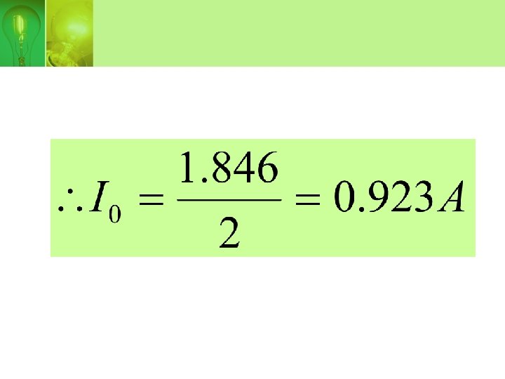
 • Calculate the value of Io")


 • Determine the value of currents, I 1, I 2 and")


")


")


 • Use superposition principle to determine the voltage Vo. +")


 • Determine the value of Vo.")


- Slides: 121
CIRCUIT ANALYSIS METHODS Topic 3
CIRCUIT ANALYSIS METHODS • • Node-Voltage method Mesh-current method Source transformation Thevenin equivalent circuit Norton equivalent circuit Maximum power transfer Superposition principle
INTRODUCTION OF NODEVOLTAGE METHOD • Use KCL. • Important step: select one of the node as reference node • Then define the node voltage in the circuit diagram.
Node-voltage example
• In the diagram, node 3 is define as reference node and node 1 and 2 as node voltage V 1 and V 2. • The node-voltage equation for node 1 is,
• Node-voltage equation of node 2,
• Solving for V 1 and V 2 yields
THE NODE-VOLTAGE METHOD AND DEPENDENT SOURCES • If the circuit contains dependent sources, the node-voltage equations must be supplemented with the constraint equation imposed by the presence of the dependent sources.
example… Use the node-voltage method to find the power dissipated in the 5Ω resistor.
• The circuit has 3 node. • Thus there must be 2 node-voltage equation. • Summing the currents away from node 1 generates the equation,
• Summing the current away from node 2 yields,
• As written, these two equations contain three unknowns namely V 1, V 2 and iØ. • To eliminate iØ, express the current in terms of node-voltage,
• Substituting this relationship into the node 2 equation,
• Solving for V 1 and V 2 gives,
• Then,
SPECIAL CASE • When a voltage source is the only element between two essential nodes, the nodevoltage method is simplified.
Example…
• There is three essential nodes, so two simultaneous equation are needed. • Only one unknown node voltage, V 2 where as V 1=100 V. • Therefore, only a single nodevoltage equation is needed which is at node 2.
Using V 1 =100 V, thus V 2=125 V.
SUPERNODE • When a voltage source is between two essential nodes, those nodes can be combine to form a supernode (voltage sourse is assume as open circuit).
Supernode example…
• Nodes chosen,
• Node-voltage equation for node 2 and 3,
• Summing both equation, Above equation can be generates directly using supernode approach
Supernode
• Starting with resistor 5Ω branch and moving counterclockwise around the supernode,
• Using V 1 =50 V and V 3 as a function of V 2,
• Substitute into the node-voltage equation,
• Using V 2 value, gives
CIRCUIT ANALYSIS METHODS • • Node-Voltage method Mesh-current method Source transformation Thevenin equivalent circuit Norton equivalent circuit Maximum power transfer Superposition principle
INTRODUCTION OF MESHCURRENT METHOD • A mesh is a loop with no loop inside it. • A mesh current is the current that exist only in the perimeter of a mesh. • Mesh-current method use KVL to generates equation for each mesh.
Mesh-current example…
• Mesh-current circuit with mesh current ia and ib.
• Use KVL on both mesh,
• Solving for ia and ib, and you can compute any voltages or powers of interest.
THE MESH-CURRENT METHOD AND DEPENDENT SOURCES • If the circuit contains dependent sources, the mesh-current equations must be supplemented by the appropriate constraint equations.
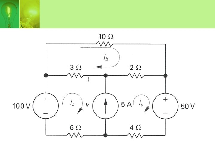
Example…
• Use the mesh-current method to determine the power dissipated in the 4Ω resistor.
• Using KVL,
• But • Substituting into the mesh-current equation,
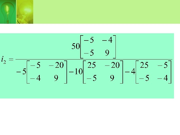
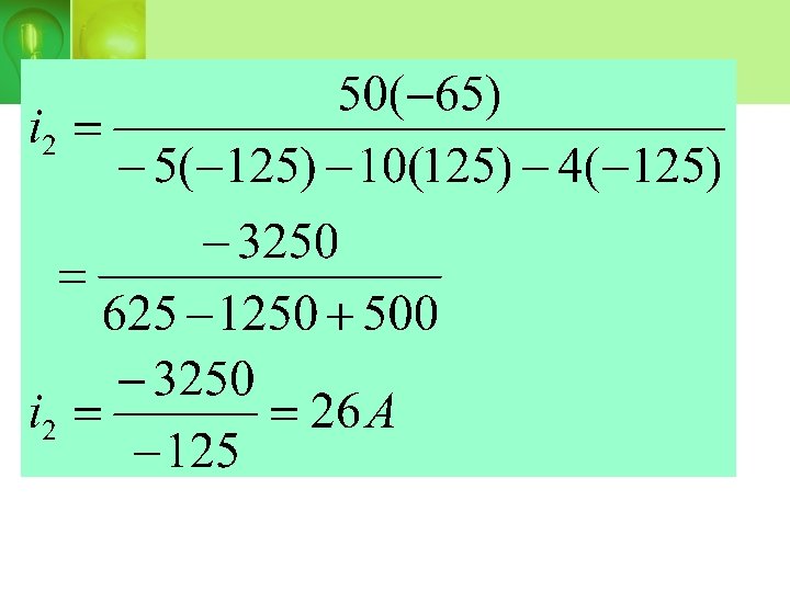
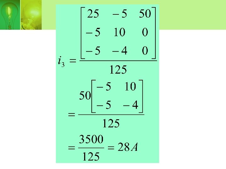
• Using Cramer rule, the values of i 2 and i 3 can be determine,
• Power dissipated by 4Ω resistor is
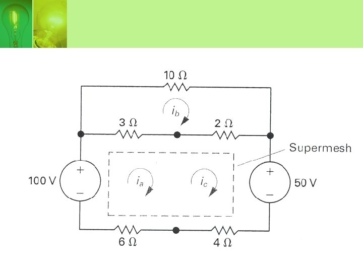
SPECIAL CASE (SUPERMESH) • When a branch includes a current source, the mesh-current method can be simplified. • To create a supermesh, remove the current source from the circuit by simply avoiding the branch when writing the mesh-current equations.
• Supermesh equation,
• Mesh 2 equation,
• From the circuit, ic –ia= 5 A • Using Cramer rule, the three mesh current can be obtain.
CIRCUIT ANALYSIS METHODS • • Node-Voltage method Mesh-current method Source transformation Thevenin equivalent circuit Norton equivalent circuit Maximum power transfer Superposition principle
SOURCE TRANSFORMATION • Source transformation allows a voltage source in series with a resistor to be replaced by a current source in parallel with the same resistor or vice versa.
Source transformation
Example…
• Source transformation procedure From To method Use,
From To method Use,
CIRCUIT ANALYSIS METHODS • • Node-Voltage method Mesh-current method Source transformation Thevenin equivalent circuit Norton equivalent circuit Maximum power transfer Superposition principle
THEVENIN EQUIVALENT CIRCUIT • Thevenin equivalent circuit consist of an independent voltage source, VTh in series with a resistor RTh.
Thevenin equivalent circuit
• Thevenin voltage, VTh = open circuit voltage in the original circuit. • Thevenin resistance, RTh is the ratio of open-circuit voltage to the short-circuit current.
Example…
• Step 1: node-voltage equation for open-circuit:
• Step 2: short-circuit condition at terminal a -b
• Node-voltage equation for shortcircuit:
Short-circuit current: Thevenin resistance:
Thevenin equivalent circuit
CIRCUIT ANALYSIS METHODS • • Node-Voltage method Mesh-current method Source transformation Thevenin equivalent circuit Norton equivalent circuit Maximum power transfer Superposition principle
NORTON EQUIVALENT CIRCUIT • A Norton equivalent circuit consists of an independent current source in parallel with the Norton equivalent resistance. • Can be derive from a Thevenin equivalent circuit simply by making a source transformation. • Norton current, IN = the short-circuit current at the terminal of interest. • Norton resistance, RN = Thevenin resistance, RTh
Example
Step 1: Source transformation
Step 2: Parallel sources and parallel resistors combined
Step 3: Source transformation, series resistors combined, producing the Thevenin equivalent circuit THEVENIN EQUIVALENT CIRCUIT
Step 4: Source transformation, producing the Norton equivalent circuit NORTON EQUIVALENT CIRCUIT
CIRCUIT ANALYSIS METHODS • • Node-Voltage method Mesh-current method Source transformation Thevenin equivalent circuit Norton equivalent circuit Maximum power transfer Superposition principle
MAXIMUM POWER TRANSFER • Two basic types of system: – Emphasizes the efficiency of the power transfer – Emphasizes the amount of power transferred.
• Maximum power transfer is a technique for calculating the maximum value of p that can be delivered to a load, RL. • Maximum power transfer occurs when RL=RTh.
Example…
• Power dissipated by resistor RL
• Derivative of p with repect to RL
• Derivative is zero and p is maximum when
• The maximum power transfer occurs when the load resistance, RL = RTh • Maximum pwer transfer delivered to RL:
CIRCUIT ANALYSIS METHODS • • Node-Voltage method Mesh-current method Source transformation Thevenin equivalent circuit Norton equivalent circuit Maximum power transfer Superposition principle
SUPERPOSITION PRINCIPLE • In a circuit with multiple independent sources, superposition allows us to activate one source at a time and sum the resulting voltages and currents to determine the voltages and currents that exist when all independent sources are activate.
Step of Superposition principle 1. Deactivated all the sources and only remain one source at one time. Do circuit analysis to find voltages or currents. 2. Repeat step 1 for each independent sources. 3. Sum the resulting voltages or currents.
REMEMBER!!! 1. Independent voltage source will become short-circuit with 0Ω resistance. 2. Independent current source will become open-circuit. 3. Dependent sources are never deactivated when applying superposition.
Example…
• Step 1: deactivated all sources except voltage source
• V 0 is calculated using voltage divider:
• Step 2: Deactivated all sources except current source
• V 0 is calculated by using current divider:
• Step 3: Sum all the resulting voltages: V 0 =2+5=7 V.
Question 1 (nodevoltage) • Calculate the value of Io
Solution • Node 1:
• Node 2:
Question 2 (mesh-current) • Determine the value of currents, I 1, I 2 and I 3.
• Supermesh: • Mesh 3:
• Dependent current source • Vo
• Substitute V 0
• Use Cramer rule
• Current I 2:
• Current I 3:
Question 3 (thevenin)
• Open-circuit voltage, Voc:
• Node-voltage equation for Voc
• Thevenin resistance, RTh:
• Thevenin equivalent circuit:
Question 4 (norton)
• Open-circuit current, Isc:
• Norton resistance, RN: RN = 4Ω
• Norton equivalent circuit:
Question 5 (superposition) • Use superposition principle to determine the voltage Vo. +
• Deactivated current source +
• Deactivated voltage source
• Summing the voltage V 0
Question 6 (node-voltage) • Determine the value of Vo.
node-voltage equation: Current iΔ:
• Thus: V 0 =50 V