CIP Training Series CIP Components Basic Components of

CIP Training Series CIP Components Basic Components of Clean-In-Place Systems Used by the Food Processing Industry Training For Sanitation Consultants and Plant Personnel

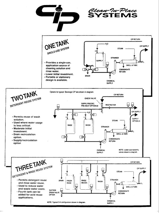
Types of Systems z Single Use System y One time solution use y Lower initial investment, but higher cleaning cost z Re-use System y Two Tank (Rinse & Wash) y Three Tank (Rinse, Wash & Rinse Recovery, or, Rinse and 2 Wash Tanks) y Four Tank (Rinse, Wash, Rinse Recovery & Acid Rinse) z Chlorinated Alkaline Wash with a injected acid sanitizer step

Water Supply Tank z Provides water to the CIP supply pump during the rinse and sanitize steps. z There may be additional tanks for cleaning solutions and for rinse water recovery. z Two guidelines to follow when sizing CIP tanks y 150% of the volume required to fill the supply and return lines (i. e. , 150% of the volume of the largest circuit washed) y 200% of the supply pump capacity in gal/min

Water Level Control z This system maintains water levels in the supply tank. z Probe style (must be kept clean and must control foam in the tank). Uses electrical probes to control solution levels. z DP cell (Differential Pressure is best allows for more fine tuning of circuits and not effected by tank foaming) z Modern CIP systems may use pressure transducers in combination with process controllers to regulate solution levels. y Using pressure indicator, PLC can finetune level control with %fill and graphics displayed

CIP Supply Pump z Usually centrifugal pumps are used z Delivers rinse, cleaning and sanitizing solutions to the equipment being cleaned. z Supply pump must be sized according to the flow requirements of the equipment being cleaned. z Can program exact flow rates for each piece of equipment if use variable speed pumps. z VFD pumps supply flow at the required flow rate for flow/pressure requirements of sprayballs and line diameters, etc.

CIP Supply Pumps z Supply y Typically 3500 rpm centrifugal pumps y Want high speed pump, flooded suction generally not a problem y Must meet the minimum velocity requirements y Variable speed beneficial when velocity requirement needs vary z Return y Typically high volume low speed 1750 rpm centrifugal pumps (usually 1. 5 -3 times more capacity than the supply pump) y Less prone to airlock than 3, 500 rpm pump z Air eliminators very important z Shaft seal in good condition and not leaking

Spray Devices z Effective cleaning is dependent upon complete coverage of all equipment surfaces with the rinse/cleaning/sanitizing solutions. z Proper spray pattern and flowrates are critical to ensure effective cleaning results. z There are many types of sprayballs, spray disks, sprayjets and other spray devices.
 y Disk Spray y")
Spray Devices z Static/Fixed y Spray Ball (180° & 360°) y Disk Spray y Spray Ring z Rotating-Auxiliary Driven z Pressure to the spray balls can be regulated y 3 ways (Restrictor orifice, throttling valve or variable speed pump) z Proper location is extremely important

Spray Devices z Flow rate requirements for vertical tank y Static Spray Ball: 0. 016 x vessel cap. = GPM y Rotating Device: 0. 011 x vessel cap. = GPM z Flow rate requirements for Horizontal tank y Static Spray Ball: 0. 022 x vessel cap. = GPM y Rotating Device: 0. 015 x vessel cap. = GPM z Must follow that manufacturer’s recommended GPM for the spray device being used y Too low will result in inadequate coverage y Too high will result in atomization causing noneffective particles y Correct flow will provide a cascading or sheeting action

Spray Devices Spray Ball

Spray Devices Spray Jet

Spray Devices Location of Spray Devices in Several Tank Configurations

Spray Devices Flow Coverage

Heat Source Methods z Immersion y Steam or electrical coils y Slow heating y Stress cracking z Jacketed Tank y High initial cost y Response time very slow y Thermal differences in and throughout the tank The following heat transfer equipment are more common and will be covered in more detail: z Direct Steam/Steam Sparger z Heat Exchangers
 z Direct Steam Injection y Steam injection into the suction side")
Heating System (continued) z Direct Steam Injection y Steam injection into the suction side of the CIP supply pump. y Steam sparge in each tank y Advantage: Solution can be preheated to proper temp thus saving time. y Disadvantage: Less effective method (~25% Btu loss) y Disadvantage: Can often cause severe “water hammer” y Disadvantage: Safety--If solution level in tank becomes too low there may be live steam injection above water line. y Disadvantage: Steam condensate is not recovered to the boiler. y Boiler chemicals in CIP solutions
 z Heat Exchanger y y y Shell-and-Tube Plate-and-Frame Fast response")
Heating System (cont. ) z Heat Exchanger y y y Shell-and-Tube Plate-and-Frame Fast response No contamination of the solution Even heating Higher initial cost
 Temperature Control z Temperature sensors (Gas filled capillary tubes, Thermocouple,")
Heating System (cont. ) Temperature Control z Temperature sensors (Gas filled capillary tubes, Thermocouple, Resistance bulb “RTD”) y RTD (Resistance Temperature Device) or Thermostats y RTDs can have multiple set points whereas there must be separate thermostats for each temperature. y RTDs provide better temperature control and have fewer problems than thermostats. z Modern CIP systems use microprocessors which control steam valves which are regulated by RTDs or thermostats to control steam and maintain the proper temperature of the solutions. z Valves are self-actuating and air-operated (throttling)

Temperature Probe and Temp. Recording Chart z Measures and records the time and return temperature of the solutions to ensure that the equipment was recirculated. z Sometimes there alarms to alert the operator if the temps are too low or too high; or there could be an emergency shutdown system if the temps are too high. z Temperature probes and recording charts are legal requirements by most regulatory agencies.

Valves z Control the direction of solution flow through the circuit. z Plug valves or Butterfly valves (manual operation). z Air-operated sanitary valves (automated operation). z Two-way valve (shutoff valve) y Normally open x A spring holds the valve in the open position and air pressure must be applied to close the valve. x In the case of air pressure failure the valve would remain open.
 y")
Valves z Automatic Sanitary design valves y Stainless Steel construction (316 or better) y Open yoke couplings y Compression Style (Molded rubber disk or Teflon o-ring on ss disk) z Plug valves y Not cleanable by CIP alone, must be removed and manually cleaned prior to CIPing y Recommend a program to replace x number per year with automatic valves z Valve pulsing y y 2 -3 times on the pre-rinse 4 -6 times during the wash 3 -4 times during the post rinse Pulse the next valve open prior to closing the previous valve to prevent “Hydraulic Shock” z Scheduled PM program is critical
 z Two-way valve (block or shut-off) y Normally Closed x A")
Valves (cont. ) z Two-way valve (block or shut-off) y Normally Closed x A spring holds the valve in the closed position and air pressure must be applied to open the valve and allow solution flow. x In the case of air pressure failure the valve would return to the closed position (good safety feature). y Air-to-open / Air-to-close valve x Air is used to hold the valve in either the open or closed position (instead of a spring).
 z Three-way valve (divert valve) y Direct solution flow to one")
Valves (cont. ) z Three-way valve (divert valve) y Direct solution flow to one of two different directions. y Solution flow is always open in one direction. When air pressure is applied it moves the valve position and directs the flow to the other port. y Example: CIP drain valve directs return flow to the supply tank or to the drain.

Cleaner/Sanitizer Feed Systems z Chemical dosing is usually done with small air pumps, diaphragm (air-operated) pumps or peristaltic pumps. z Cleaning chemicals are typically dispensed into the CIP wash tank. z Sanitizers are typically injected into the inlet manifold of the CIP supply pump. (Requires an electric solenoid to prevent the sanitizer from siphoning during the rinse and wash cycles, or, air-to-open and spring-to-close is common).
 z Sanitizer injection feed rate needs to be at")
Cleaner/Sanitizer Feed Systems (cont. ) z Sanitizer injection feed rate needs to be at the proper ratio to the water flowrate to ensure proper sanitizer concentration. y Usually a small needle valve is used to calibrate the sanitizer feedrate. z Chemical concentration control is based on conductivity, timed feed or pulse feed. z Conductivity cells are located in the solution tanks or inline on the discharge side of the supply pump, or return line to CIP tanks (CIP validation).

CIP Controller Proper Programming to Control a CIP System z Controls the functions of pumps, valves and other components (e. g. , air blows). z Manages flow times, flow direction z Controls and monitors solution temperatures, water levels and solution flowrates/pressures. z Controls CIP safety system to shut down the CIP supply pump if temperatures are excessive, supply tank solution levels are low, or for incorrect circuit connections.
 CIP Control Types 1. Electronic Sequencer y y y 2.")
CIP Controller (cont. ) CIP Control Types 1. Electronic Sequencer y y y 2. Operates simple CIP’s No logic; Step controls energize outputs for a preset time, then advance according to the programmed time Documentation typically on circular charts Microprocessor y y Preprogrammed dedicated CIP controllers Functions mainly limited to predefined system configuration; user definable operating parameters
 CIP Control Types 3. PC Based y User friendly; programmed")
CIP Controller (cont. ) CIP Control Types 3. PC Based y User friendly; programmed in standard CIP language y Computer or PLC programming knowledge not needed y Each CIP circuit can have individualized program y Programs/CIP parameters documented automatically y Specific CIP software available 4. Programmable Logic Controller (PLC) y Can operate even the most complex systems y Programming must be documented, for validation and especially for any future changes y Allen-Bradley PLC’s and displays typical y Chart recorders for documentation
 z Modern CIP control systems are often based on microprocessor")
CIP Controller (cont. ) z Modern CIP control systems are often based on microprocessor or PLC-programmable logic computers. y Relatively easy to make program changes (time, temp, water levels, etc). y Capable of controlling many functions of the CIP system.
 z Older CIP control systems may be based on Tenor")
CIP Controller (cont. ) z Older CIP control systems may be based on Tenor drums pin charts, punched program cards or cam timers y Usually more difficult to make program changes x Cams set on cam timers, insert pins on drum timers; dedicated programmer needed y Limited capability for controlling functions of the CIP system. Small/old CIP systems may not have any CIP control system. Manual operator control for all CIP functions (time, temp, valves, etc. ).

Piping for CIP Solutions z Need piping to transfer the rinse/cleaning/sanitizing solutions from the rinse/solution tanks to the equipment being cleaned. Frequently the product lines are also used as the CIP supply lines. z Also need CIP return lines and a CIP return pump to return the solutions to the drain or to the solution tanks. z Supply and return lines are necessary to complete the circuit in order for recirculation to occur.
 z Usually there is an air eliminator just")
Piping for CIP Solutions (cont. ) z Usually there is an air eliminator just prior to the return pump; the air eliminator helps prevent the pumps from becoming “air locked”. z Frequently there is a screen located in the supply line to prevent debris from interfering with the operation of valves, pumps and spray devices. y Usually located after CIP supply pump(s) and prior to heatchanger(s).
 z Distribution plates and swing elbows are used to complete the")
Flowverters (Distribution Plates) z Distribution plates and swing elbows are used to complete the CIP supply and return circuits. z Modern CIP systems have proximity switches on the distribution plate to ensure correct circuit hookup.

Air Blows z After recirculation is completed the piping remains full of rinse water, cleaning or sanitizing solutions. z An air blow is used to empty the supply and return piping at the end of selected steps. z The air blow is sometimes used to apply sanitizing solutions to the equipment; it is also used to return rinse water to the drain and cleaning solutions to their reclaim tanks.
 z There is usually a 1 micron filter on the")
Air Blows (cont. ) z There is usually a 1 micron filter on the injection fitting to prevent microorganisms from contaminating the equipment surfaces by the air supply.

Flow Controls z Most spray devices provide optimum cleaning performance when they are operated within specific flow and pressure ratings. z Low flowrates or pressures could result in poor cleaning results. z High pressures can increase atomization of cleaning solutions. z On many CIP systems where there are different types of equipment being cleaned (tankers, silos, line circuits) there may be different flow requirements for each type of equipment.
 z A flow meter (vane type or vortex type) may")
Flow Controls (cont. ) z A flow meter (vane type or vortex type) may be used in conjunction with a variable speed pump or a throttling valve to regulate flows or pressures for the various circuits. Mag flow meters provide excellent control. z The microprocessor/computer uses the input data from the flowmeter (or pressure sensor) to regulate pump speed (or throttling valve) to achieve the proper flowrates.
 z If the CIP system does not have variable speed")
Flow Controls (cont. ) z If the CIP system does not have variable speed pumps (or throttling valves) a flow restrictor (orifice) can be placed inline to provide flow control for the various circuits. The flow restrictor can be welded in the supply line or fitted with a gasket and placed inline at a pipe connection.

Pressure Sensors z Many CIP systems monitor and record supply pressures. z Low pressures may indicate an open circuit. z High pressures could indicate a plugged spray device. z Fluctuating pressures may indicate poor hydraulics. y Often this can be observed on the circular chart

Chemical Dosing Probes z Avoid manual addition y Chemical waste y Safety concern y Poor solution strength consistency z A conductivity probe may be used to control the concentration of cleaners (and sanitizers). z Conductivity controlled y Preferred method in combination with air-operated (diaphragm) chemical dispensing pumps z Conductivity y Measures the lack of resistance y Unit of measure is usually in millisiemens (m. S) or microsiemens (u. S) y Probes x Electrode and electrodeless x K-Factor must be matched with the meter for the correct range of solution to be measured y Location of the measuring probe and dosing point is critical y Concentration testing on a regular basis is necessary to verify the automatic controls are working correctly

Conductivity Probe z The conductivity probe may be placed in the chemical supply tank or in the supply line. z If a conductivity probe is placed in the return line it can be used to control/monitor rinses to minimize water usage z Supply and return probes are used to improve operational efficiencies/fine tune control (or return probe and intank probe) z In order to ensure accurate conductivity control it is necessary that the conductivity probe be kept clean of mineral film and other soil materials (drawback of in-tank).
 cleaner concentrations are controlled")
p. H Electrode z For some applications (membrane filtration systems) cleaner concentrations are controlled by p. H. z In some cases p. H probes are used to monitor/adjust the acidity of food products. z Since most p. H electrodes are made of glass they should be located in a side stream to prevent potential glass contamination. z p. H electrodes are more likely to become fouled than conductivity probes. p. H electrodes should be calibrated and maintained daily.

Sensors - CIP z Return probes/sensors located just prior to CIP tanks. z Return sensors (temperature, conductivity, and flow) are often placed together on return pipe via connection ports on horizontal pipe section. z CIP time via PLC controller and recorded on circular chart–thus, all four cleaning factors controlled and monitored. z Required for validation/verification of CIP parameters.

Data Acquisition z Most CIP systems have some type of recording charts to monitor temperature. z Circular pen charts have been used for many years. z Modern microprocessors have the capability of monitoring and electronically recording up to 15 (and sometimes more) functions of the CIP system. y Some of these functions are temperature, pressures, conductivity, p. H, water levels, valve function/position, etc.
 z CIP system data can be electronically stored and used")
Data Acquisition (cont. ) z CIP system data can be electronically stored and used to document food quality and food safety programs.

CIP Component Training Thank you for your time! Questions?
- Slides: 46