Chiller Plant Manager CPM 2017 Rev C 1252020


- Slides: 25

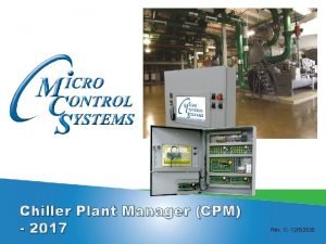
Chiller Plant Manager (CPM) - 2017 Rev. C- 12/5/2020

Overview § Designed to control a site that consists of multiple chiller packages controlled by individuall MCS-MAGNUMS § Plant Manager will control the process pumps to ensure required water flow § CPM will stage the chiller packages to meet the cooling requirements of the site § CPM compares the control temperature to temperature target, setpoint 4 CPM TARGET and develop the step capacity needed. § Supports up to 15 individual pumps § Supports up to 5 Pump Groups § Can control each pump independently or as a group § Communications via the RS 485 port or hardwired to Magnum controllers. § Provide Run/Stop and staging capacity. § Provide alarm status of Magnum on the network.

Overview (Continued) § Supports up to 12 pumps or fans per loop. Supports 16 cooling/ice making and heating stages per loop. Supports 1 VFD for pumps or fans per loop with unique control sensor. Supports 1 VFD for heating stages per loop. § Supports 1 VFD for cooling stages per loop. § § §

Overview (Continued) § § § Supports up to 80 Relay Outputs. Supports up to 112 Sensors Inputs. Supports up 28 Analog Outputs. Supports 255 Set points. Supports storage of last 99 alarms. Supports 1008 History Samples for all inputs & outputs.

Customizable Graphical Interface

Customizable Graphical Interface

MCS-POWERMETER - Optional Rope Current Transformers Features: • Provides Voltages - 3 Phase (up to 600 VAC) • Provides Ampere – 3 Phases (up to 5000 A) • Provide Energy Usage (KWH) • Provides Real Power (KW) • Provides Peak Demand (KWDemand) • Provides Power Factor

Set Points and Descriptions SP # NAME DESCRIPTION TYPE 1 Cool. Deadban d High Zone - Adds to the CPM Target to determine cut in temperature for Cooling Low Zone - Subtracts from CPM Target to determine cut off temperature for Cooling Target 3 CPM Ratio Multiplier A: Determines the numerator value for chiller capacity % adjustment scaling (variable chillers only) Divider A: Determines the denominator value for chiller capacity % adjustment scaling (variable chillers only) Multiplier B: Determines the numerator value for scaling the step delay decrement Divider B: Determines the denominator value for scaling the step delay decrement Digital SW 4 CPM Target Value - Determines the target temperature for chillers to maintain Max Time Allowed - Determines the step delay for chiller capacity control Zone - Determines the zone value (both positive and negative) for chiller capacity control Max ROC - Determines the maximum positive ROC for chiller capacity control TARGE T

SP # 5 NAME CPM ADJUST DESCRIPTION Value - Determines minimum % adjustment for chiller capacity (variable chillers TYPE Delay only) Min VFD Opening - Determines the minimum capacity % for chiller capacity (variable chillers only) Max VFD Opening - Determines the maximum capacity % for chiller capacity (variable chillers only) Max VFD Adjustment - Determines maximum % adjustment for chiller capacity (variable chillers only) 6 CPM ROC Multiplier A: Determines the numerator value for chiller capacity % adjustment scaling (variable chillers only) Divider A: Determines the denominator value for chiller capacity % adjustment Digital SW scaling (variable chillers only) Multiplier B: Determines the numerator value for scaling the step delay decrement Divider B: Determines the denominator value for scaling the step delay decrement 26 Pmp. A-C On-On Value - Determines the minimum amount of time between pumps turning on SP 27 Pmp. A-COff -On Value - Determines the minimum amount of time after a pump turns off before it is allowed to turn on again SP

SP # NAME DESCRIPTION TYPE 36 LD CHL DAYS Similar to lead circuit days logic SP 37 P-PMP LEAD Like Lead Chiller, except for Pump Group #1 38 P-PMP DAYS Like Lead Chiller Days, except for Pump Group #1 SP 47 Pump. Predel ay Value - Determines minimum amount of time pump must have flow before chillers are allowed on SP 48 PValue - Determines how long after run stop switch is flipped that at Pmp. Post. Dly least one pump stage will continue to run SP 59 Cool Stg Dly Value - This setpoint determines how long cooling will hold in a staging delay once a stage is added or subtracted from the capacity SP 60 Iso. Vlv. Cls. Dl y Value - When a chiller shuts down due to lockout or normal shutdown, this setpoint defines how long the CPM will wait before closing the isolation valve for that chiller. If this setpoint is inactive, it will default to 30 seconds. SP 61 No. Iso. Vlv. Prf If active, this setpoint will lock out a chiller if an isolation valve is requested open for a certain period of time (defined by the setpoint) and proof is not given to the CPM. TIME LOCKO UT

Setting up Config for CPM

Setting up Config Chillers

Chiller Control Algorithm § The chiller control algorithm is used to determine how many chiller stages need to be on in order to maintain a target control temperature. § The algorithm will open isolation valves for each chiller as needed. § The chiller control algorithm will only allow the maximum number of primary chillers (as defined in the configuration) on. The other chillers will not turn on unless one of the primary chillers get locked out. § The chiller control uses the standard capacity control algorithm. It uses the following setpoints. ü Setpoint #1: Cooling Deadband (note: only the low zone is used from this setpoint to determine the cooling shutoff temperature) ü Setpoint #3: CPM Cooling Ratio ü Setpoint #4: CPM Cooling Target ü Setpoint #5: CPM Cooling Adjust ü Setpoint #6: CPM Max Dropping ROC

Setting up Config Pump Info

Pump Control Algorithm Depending on the configuration, pump groups can be set up to control a number of different ways. § Staged based on # of chillers on: Specified in the configuration, up to the max limit of pumps allowed. § Water Out Temperature This will stage and modulate the pumps in that group to maintain a water out temperature § Pump Out PSI This will stage and modulate the pumps in that group to maintain a pump out pressure § Pump Differential Pressure This will stage and modulate the pumps to maintain a differential between the pump in and the pump out pressure

Setting up Config Sensor Inputs

Control Logic § CPM is powered on, it will enter 60 second power up delay § After 60 seconds, CPM will ensure that it is allowed to run by checking for any unit lockouot conditions § If there are unit lockout conditions, CPM will lock out all compressors and pumps § If there are no unit lockout, CPM will check for stop conditions. § If these cond. Itions are statisfied, CPM will allow pumps to operate Stop conditions include the following: 1. Unit Run/stop Switch is off 2. Unoccupied if Schedule is set to shut the unit off 3. BMS Run/Stop Switch=OFF

§ For pump operation, CPM will check the configuration to ensure that all isolation valves are properly opened before turning on their respective pump or pump groups. § Once the pumps are operational and the minimum predelay times are satisfied, CPM will allow the chiller control to change the unit state § Once the chiller capacity control is allowed, the CPM will use the chiller capacity control algorithm to determine whether the CPM needs to enter cooling mode. § If the CPM Cooling Target setpoint is active, the CPM is allowed to activate its cooling mode. § The temperature to enter cooling mode is determined the following way: 1. The CPM cooling target is established from Setpoint 4 (CPM Cooling Target) 2. The high zone (setpoint 1, Cooling Deadband – High Value) is added to the CPM cooling target § Once the chilled water control temperature rises above the temperature required to enter cooling, the CPM will enter cooling mode.

§ Once the CPM is in cooling, the following conditions will cause it to leave cooling: No demand for cooling when CPM is at minimum capacity 1. Run stop Condition 2. CPM Safety Condition 3. All pumps locked out § In cooling mode, the CPM will use the standard capacity control algorithm to turn chiller stages on and off as needed.

Load Options § Sequential Loading – More Capacity- The first chiller will be loaded to its full capacity before the next one is enabled to run. It will then be loaded. – Less Capacity- Lead chiller will be completely unloaded and run enable will be stopped. The next chiller will then be unloaded.

Load Options (Continued) § Balance Loading – More Capacity- All chillers will be enabled to run and will be loaded equally. – Less Capacity- All chillers will be unloaded equally.

Communications § § Plant Manager will communicate to Magnum on the network based upon Chiller information. Standard class 55 messages are used for communications.

Alarms § LOST Magnum #x – This alarm indicates that Magnum at address x is not communicating. § ALARMon. Magnum #x – This alarm indicates that Magnum at address x has encountered an alarm.

Typical Configuration for 3 Chiller

For additional information please visit our website www. mcscontrols. com 5580 Enterprise Pkwy. Fort Myers, FL 33905 Office: 239 -694 -0089 Fax: 239 -694 -0031
 What is chiller plant manager
 Formula velocidad angular
 Central plant optimization
 Senior manager vs general manager
 Portfolio manager synergy manager parental developer
 Exv driver
 Qqqqqwe
 Chiller room ventilation requirements
 Chiller diagnosis
 China magnetic suspension inverter chiller
 Free cooling chiller
 Chiller approach temperature
 Blue star water chiller
 Industrial frigo chiller
 Chiller inspection report
 York yvaa
 Four market forms of meat
 Tronsmo plant pathology and plant diseases download
 Sem vi
 Tronsmo plant pathology and plant diseases download
 Plant breeding for disease resistance
 Tronsmo plant pathology and plant diseases download
 Plant introduction in plant breeding
 Nat rev cancer
 Rev 20:15
 Rev 2:1
