CHEMICAL MACHINING CHM Introduction 1 In CHM material
")

 Schematic illustration of the chemical machining process. Note that no")


 Missile skin-panel section contoured by chemical milling to improve the stiffness-to-weight")


 1. The use of photoresists in CHM, called photochemical machining")


 Reasons for using etch band: -To obtain uniform profiles on")
 The width of the etch band on the band mask")


- Slides: 39
CHEMICAL MACHINING (CHM)
Introduction 1. In CHM, material is removed from a workpiece by exposing it to a chemical reagent or etchant. The mechanism for metal removal is the chemical reaction between the etchant and the workpiece resulting in dissolution of the workpiece. 2. Chemical machining (CM) was developed based on the observation that chemicals attack metals and etch them, thereby removing small amounts of material from the surface. This process is carried out by chemical dissolution, using reagents or etchants, such as acids and alkaline solutions. 3. Chemical machining is the oldest of the nontraditional machining processes, and has been used to engrave metals and hard stones, in deburring, and more recently in the production of printed-circuit boards and microprocessor chips. 4. The most common method of CHM involves covering selected areas of the workpiece with a maskant (or etch resist) and imparting the remaining exposed surfaces of the workpiece to the etchant.
Chemical Machining Figure. (a) Schematic illustration of the chemical machining process. Note that no forces or machine tools are involved in this process. (b) Stages in producing a profiled cavity by chemical machining; note the undercut.
Steps in CHM 1. Cleaning operation is to ensure that material will be removed uniformly from the surfaces to be etched. Contaminants on the surface of the workpiece are removed to prepare for application of the maskant and permit uniform etching. This may include degreasing, rinsing, and/or pickling. A good cleaning process produces a good adhesion of the masking material. There are two cleaning methods; mechanical and chemical methods. The most widely used cleaning process is chemical method due to less damages occurred comparing to mechanical one. 2. Masking A protective coating called a maskant is applied to certain portions of the part surface. This maskant is made of a material that is chemically resistant to the etchant. It is therefore applied to those portions of the work surface that are not to be etched. If selective etching is desired, an etch-resistant maskant is applied and selected areas of the workpiece are exposed through the maskant in preparation for etching. The selected masking material should be readily strippable mask, which is chemically impregnable and adherent enough to stand chemical abrasion during etching.
Steps in CHM 3. Etching This is the material removal step. The part is either immersed in an etchant or an etchant is continuously sprayed onto the surface of the workpiece. The chemical reaction is halted by rinsing. This process is generally carried out in elevated temperatures which are depended on the etched material. Then the etched workpiece is rinsed to clean etchant from machined surface. 4. Stripping/ demasking The maskant is removed from the workpiece and the surface is cleaned.
Procedure for CHM 1. If the part to be machined has residual stresses from prior processing, the stresses should first be relieved in order to prevent warping after chemical milling. 2. The surfaces are thoroughly degreased and cleaned to ensure good adhesion of the masking material and uniform material removal. Scale from heat treatment should also be removed. 3. The masking material is applied. Masking with tapes or paints (maskants) is a common practice, although elastomers (rubber and neoprene) and plastics (polyvinyl chloride, polyethylene, and polystyrene) are also used. The maskant material should not react with the chemical reagent. 4. The masking that covers various regions that require etching is peeled off by the scribe-and-peel technique.
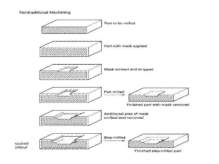
Procedure for CHM 5. The exposed surfaces are etched with etchants such as sodium hydroxide (for aluminum), solutions of hydrochloric and nitric acids (for steels), or iron chloride (for stainless steels). Temperature control and stirring during chemical milling is important in order to obtain a uniform depth of material removed. 6. After machining, the parts should be washed thoroughly to prevent further reactions with any etchant residues. 7. The rest of the masking material is removed and the part is cleaned and inspected. 8. Additional finishing operations may be performed on chemically milled parts. 9. This sequence of operations can be repeated to produce stepped cavities and various contours.
Process Capabilities • Chemical milling is used in the aerospace industry to remove shallow layers of material from large aircraft components, missile skin panels, and extruded parts for airframes. • Tank capacities for reagents are as large as 3. 7 m X 15 m (12 ft X 50 ft). • The process is also used to fabricate microelectronic devices.
Etchants are the most influential factor in the chemical machining of any material. Various etchant are available due to workpiece material.
Etch Factor, E The etch factor, E, in chemical machining is defined as: Undercutting in Photo Chemical Machining. E=d/U Where; d is the depth of cut, U is the undercut Along with the penetration into the workpiece, etching also occurs sideways under the maskant
Etch rate 1. Workpiece is etched for a duration necessary to produce the required depth of etching. E=d/t , (micron/min or mm/min) depth of etch= d (micron or mm), etching time= t (min) rate of etching E (per side) Example: If thickness of material is 3. 0 mm, etching time is 10 min and thickness of material after simultaneously etching from both side is 2. 5 mm, E= (3. 0 -2. 5)/ (2 x 10)= 0. 5/20 = 0. 025 mm/min
Effect of the etch factor in Chemical Machining from one side and both sides of a plate
Advantages 1. 2. 3. 4. 5. 6. 7. Except for the preparation of the artwork and photo tool, screen or scribing template, the process is relatively simple, does not require highly skilled labor, induces no stress or cold working in the metal, and can be applied to almost any metal— aluminum, magnesium, titanium, and steel being the most common. Large areas can be machined; tanks for parts up to 12 by 50 ft and spray lines up to 10 ft wide are available. Machining can be done on parts of virtually any shape. Thin sections, such as honey comb, can be machined because there are no mechanical forces involved. Useful and economical for weight reduction. Tolerances in chemical milling increase with the depth of the cut and with faster etch rates and vary for different materials. The surface finish is generally good.
Disadvantages 1. CHM requires the handling of dangerous chemicals and the disposal of potentially harmful by products although some recycling of chemicals may be possible. 2. The metal removal rate is slow in terms of the unit area exposed. 3. However, because large areas can be exposed all at once, the overall removal rate may compare favorably with other metalremoval processes, particularly when the work material is not machinable or the workpiece is thin and fragile, unable to sustain large cutting forces.
Design consideration for CHM 1. Because the etchant attacks all exposed surface continuously, design involving sharp corner, deep and narrow cavities, severe tapers, folded seams, or porous workpiece materials should be avoided. 2. Because the etchant attacks the material in both vertical and horizontal direction, undercuts may developed. Typically, tolerances of ± 10% of the material thickness can be maintained in chemical blanking. 3. In order to improve the production rate, the bulk of the workpiece should be shaped by other processes (such as by machining) prior to chemical machining.
Design consideration for CHM 4. Dimensional variations can occur because of size changes in artwork due to humidity and temperature. This variation can be minimized by properly selecting artwork media and by controlling the environment in the artwork generation and the production area in the plant. 5. Many product designs now are made with computer-aided design (CAD) system. However, product drawings must be translated into a protocol that is compatible with the equipment for photochemical artwork generation.
Question Chemical milling is used to make rectangular pockets. The starting thickness of the workpart is 20 mm. A series of rectangular-shaped pockets 5 mm deep are to be formed with dimensions 100 mm by 200 mm. The radius of each corner is 10 mm. The part is an aluminum alloy and the etchant is Na. OH. The penetration rate for this combination is 0. 02 mm/min and the etch factor is 1. 5. Determine: (a) metal removal rate in mm 3/min, (b) time required to machine to the specified depth, and (c) required dimensions of the opening in the cut and peel maskant to achieve the desired pocket size on the part.
Solution Given; thickness = 20 mm Pockets = 100 mm x 200 mm x 5 mm Radius corner = 10 mm Aluminum alloy Etchant is Na. OH Penetration rate = 0. 02 mm/min Etch factor = 1. 5 Solution a. Metal removal rate = Area x feed rate MRR = (Area rectangular – πD 2/4) x feed rate MRR = (100 mm x 200 mm – π202/4) x 0. 02 mm/min MRR = (19685. 80 mm 2) x 0. 02 mm/min MRR = 393. 716 mm 3 b. Time required = depth of cut / feed rate t = 5 mm / 0. 02 mm/min t = 250 min c. Desired pocket size is 100 x 200 mm with radius 5 mm. Etch factor, E = d/U Undercut = d/E U = 5 mm/1. 5 U = 3. 33 mm Size maskant = Pocket size – (3. 33 x 2) Therefore 100 – 6. 66, 200 – 6. 66 = 93. 34 mm x 193. 34 mm radius=10 mm - 3. 33 = 6. 66 mm
Chemical machining processes • Chemical milling • Chemical blanking • Chemical engraving • Photochemical machining
Chemical Milling (a) Missile skin-panel section contoured by chemical milling to improve the stiffness-to-weight ratio of the part. (b) Weight reduction of space launch vehicles by chemical milling aluminumalloy plates. These panels are chemically milled after the plates have first been formed into shape by processes such as roll forming or stretch forming. The design of the chemically machined rib patterns can be modified readily at minimal cost.
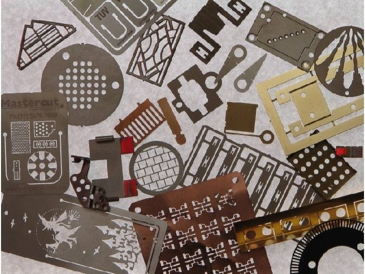
Chemical Blanking • • • Chemical blanking uses chemical erosion to cut very thin sheet metal part, down to 0. 025 mm thick. Chemical blanking is similar to the blanking of sheet metal in that it is used to produce features which penetrate through the thickness of the material. Conventional punch-and-die methods do not work because the stamping forces damage the sheet metal. Typical applications for chemical blanking are the burr-free etching of printed-circuit boards, decorative panels, and thin sheet-metal stampings, as well as the production of complex or small shapes.
Chemical engraving • Chemical machining process for making name plates and other flat panels that have lettering and/or artwork on one side. • The sequence in chemical engraving is similar to other CHM processes, except that a filling operation follows etching. The purpose of filling is to apply paint or other coating into the recessed area that have been created by etching. Then the panel is immersed in a solution that dissolved the resist but does not attack the coating material. Thus, when the resist is removed, the coating remains in the etched areas but not in the areas that were masked. The effect is to highlight the pattern.
Photo Chemical machining (PCM) 1. The use of photoresists in CHM, called photochemical machining (PCM). The most common and most precise method for creating maskants involves the use of UV light-sensitive emulsions, called photoresists. 2. In this method, photoresists are applied to the surface of the workpiece and selectively exposed to an intense ray of UV light through a photographic negative of the image to be patterned. 3. PCM has been widely used for the production of small, complex parts such as printed circuit boards and very thin parts that are too small or too thin to be blanked or milled by ordinary sheet metal forming or machining operations, respectively. Refinements to the PCM process are used in the microelectronics industry to etch metal and dielectric thin films. 4. The photochemical term can be applied correctly to chemical blanking and chemical engraving when these methods use the photographic resist method.
Photochemical Blanking • Photochemical blanking, also called photoetching, is a modification of chemical milling. • Material is removed, usually from flat thin sheet, by photographic techniques. • Complex burr- free shapes can be blanked on metals as thin as 0. 0025 mm (0. 0001 in. ). • Sometimes called photochemical machining, the process is also used for etching.
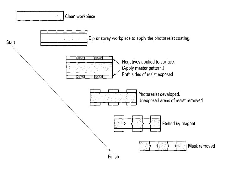
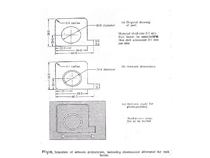
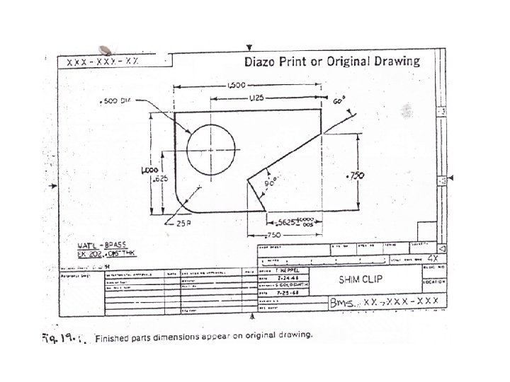
Procedure in photochemical blanking 1. The design of the part to be blanked is prepared. A photographic negative is then made and reduced to the size of the finished part. The reduced negative of the design is called artwork. The original (enlarged) drawing allows inherent design errors to be reduced by the amount of reduction (such as 100 X) for the final artwork image. 2. The sheet blank is coated with a photosensitive material (photoresist) by dipping, spraying, or roller coating, and dried in an oven. This coating is often called the emulsion. 3. The negative (stencil) is placed over the coated blank and exposed to ultraviolet light, which hardens the exposed areas. 4. The blank is developed, which dissolves the unexposed areas. 5. The blank is then immersed into a bath of reagent (as in chemical milling), or sprayed with the reagent, which etches away the exposed areas. 6. The masking material is removed, and the part is washed thoroughly to remove all chemical residues.
Procedure in photochemical blanking 1. 2. 3. 4. 5. 6. 7. Clean raw part Apply resist (maskant) by dipping, spraying or painting Place negative on resist Expose to ultraviolet light Develop to remove resist from areas to be etched Etch partially until completed both side Remove resist and clean to yield finished part.
Types of Photoresist
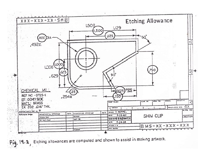
Design consideration for PCM Etching allowance- the artwork dimensions are made to match those of the component plus or minus the etching allowance due to undercut (side etching). Three types of dimensions: 1. Dimensions that decrease with etching time. Example outside dimension, distance between an edge and a hole centre. 2. Dimensions that increase with etching time. Example: hole diameter, width of slot. 3. Dimensions that remain constant with etching time. Example: angle, distance between centres. Etch band-A line with uniform width drawn on the artwork and hence reproduced on stencil.
Design consideration (cont. ) Reasons for using etch band: -To obtain uniform profiles on all edges. Rate of etching is dependent on stencil line width. -To conserve etchant.
Design consideration (cont. ) The width of the etch band on the band mask should be equal to the width of the smallest aperture on the mask or approximately 0. 8 mm if the smallest aperture is wider than 1 mm. Etching tabs-triangle bridges across and along the outside etch band with apex towards the component. This apex should be etched almost to a part (0. 1 mm) after processing. Function of tabs: 1. To prevent components separating from the main sheet and lost in the etchant. 2. To prevent components becoming entangled.
Comparison between PCM and CHM 1. CHM involves bulk material removal, in engineering application involves structural components 2. PCM involves low depths of cut on flat sheet materials. 3. CHM employs a hard-metal template and hand scribing. 4. PCM combines chemical etching with micro-photography and photosensitive maskants.
PCM Capabilities 1. Typical applications for photochemical blanking are fine screens, printed-circuit cards, electric-motor laminations, flat springs, and masks for color television. Although skilled labor is required, tooling costs are low; the process can be automated; and it is economical for medium- to highproduction volume. 2. Photochemical blanking is capable of making very small parts where traditional blanking dies are difficult to produce. The process is also effective for blanking fragile workpieces and materials. 3. The handling of chemical reagents requires precautions and special safety considerations to protect the workers against exposure to both liquid chemicals and volatile chemicals. 4. Furthermore, the disposal of chemical by-products from this process is a major drawback, although some by-products can be recycled.
Lecture highlights • General steps of chemical machining. • Terms: etching, etchant, etch rate etc • Illustration and step sequences of processing in chemical machining and photochemical machining. • Design consideration of PCM