
CHEMCAD Seminar Transport and Storage John Edwards PI

- Slides: 34
CHEMCAD Seminar Transport and Storage John Edwards, P&I Design Ltd January 2015 www. chemstations. com
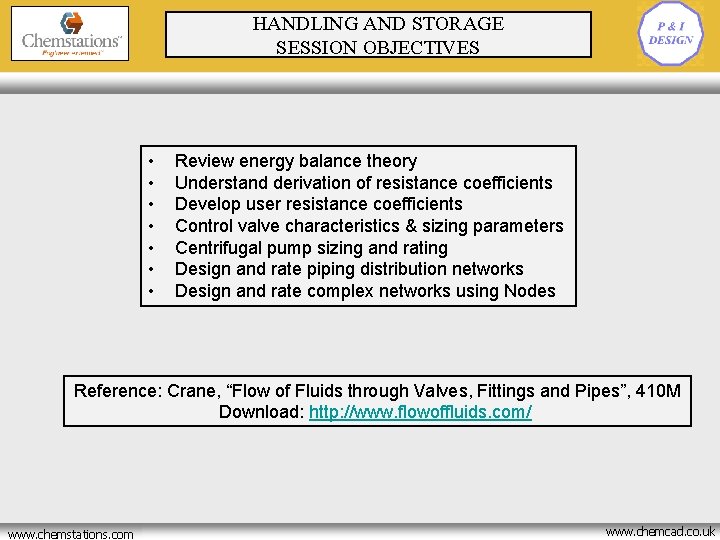
HANDLING AND STORAGE SESSION OBJECTIVES • • Review energy balance theory Understand derivation of resistance coefficients Develop user resistance coefficients Control valve characteristics & sizing parameters Centrifugal pump sizing and rating Design and rate piping distribution networks Design and rate complex networks using Nodes Reference: Crane, “Flow of Fluids through Valves, Fittings and Pipes”, 410 M Download: http: //www. flowoffluids. com/ www. chemstations. net www. chemstations. com www. chemcad. co. uk
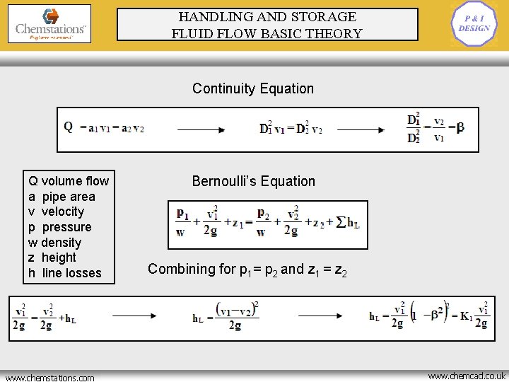
HANDLING AND STORAGE FLUID FLOW BASIC THEORY Continuity Equation Q volume flow a pipe area v velocity p pressure w density z height h line losses www. chemstations. net www. chemstations. com Bernoulli’s Equation Combining for p 1= p 2 and z 1 = z 2 www. chemcad. co. uk
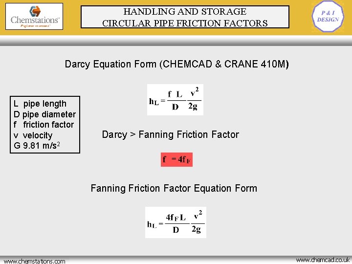
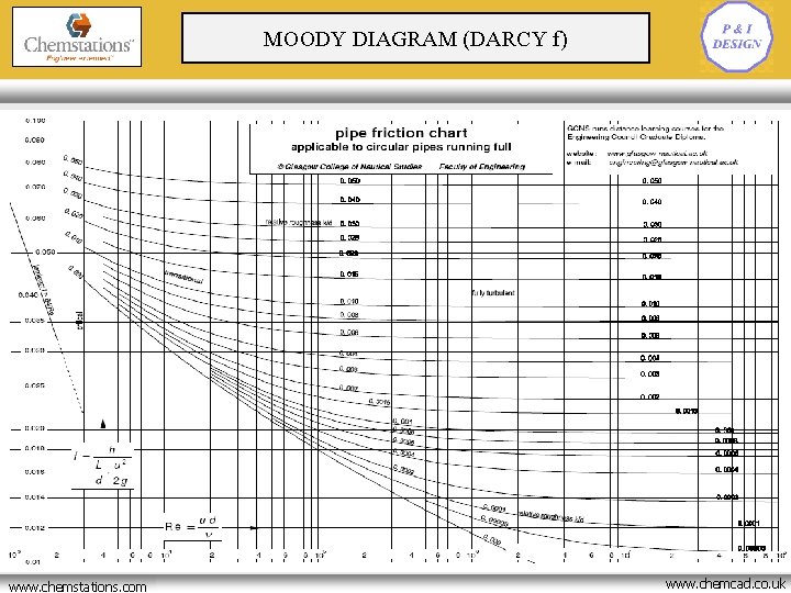
HANDLING AND STORAGE CIRCULAR PIPE FRICTION FACTORS Darcy Equation Form (CHEMCAD & CRANE 410 M) L pipe length D pipe diameter f friction factor v velocity G 9. 81 m/s 2 Darcy > Fanning Friction Factor Equation Form www. chemstations. net www. chemstations. com www. chemcad. co. uk
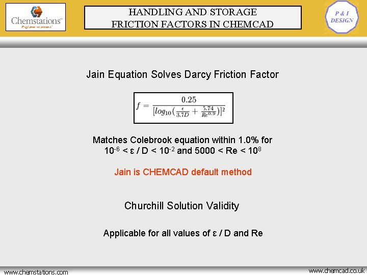
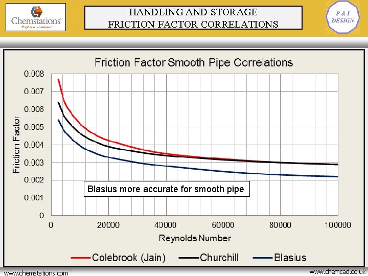
HANDLING AND STORAGE FRICTION FACTORS IN CHEMCAD Jain Equation Solves Darcy Friction Factor Matches Colebrook equation within 1. 0% for 10 -6 < ε / D < 10 -2 and 5000 < Re < 108 Jain is CHEMCAD default method Churchill Solution Validity Applicable for all values of ε / D and Re www. chemstations. net www. chemstations. com www. chemcad. co. uk
MOODY DIAGRAM (DARCY f) www. chemstations. net www. chemstations. com www. chemcad. co. uk
HANDLING AND STORAGE FRICTION FACTOR CORRELATIONS Blasius more accurate for smooth pipe www. chemstations. net www. chemstations. com www. chemcad. co. uk
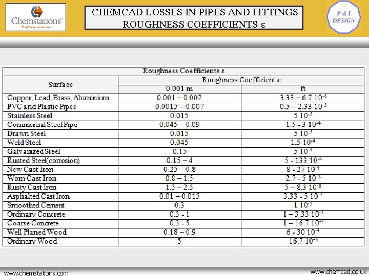
CHEMCAD LOSSES IN PIPES AND FITTINGS ROUGHNESS COEFFICIENTS ε www. chemstations. net www. chemstations. com www. chemcad. co. uk
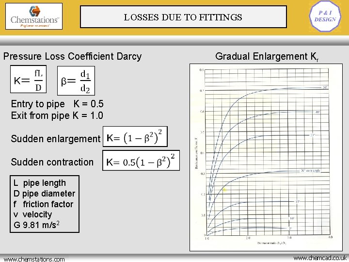
LOSSES DUE TO FITTINGS Pressure Loss Coefficient Darcy Gradual Enlargement Kr Entry to pipe K = 0. 5 Exit from pipe K = 1. 0 Sudden enlargement Sudden contraction L pipe length D pipe diameter f friction factor v velocity G 9. 81 m/s 2 www. chemstations. net www. chemstations. com www. chemcad. co. uk
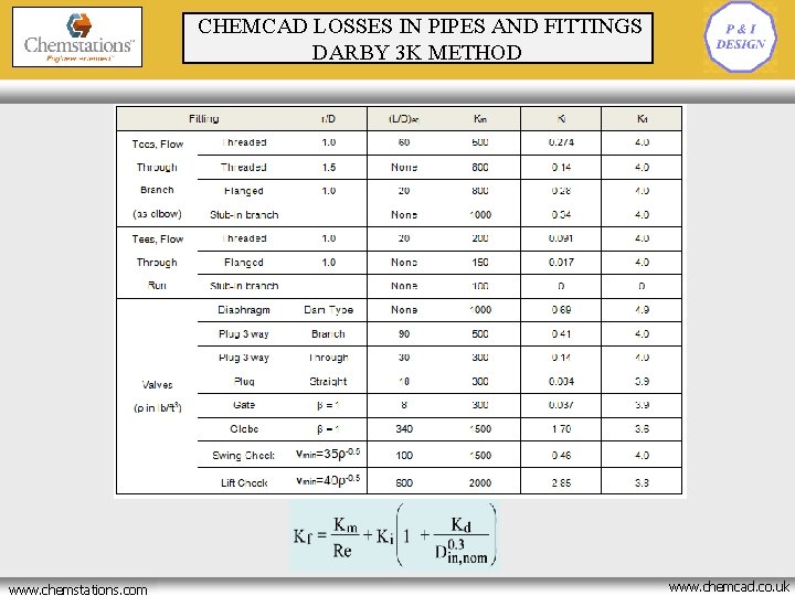
CHEMCAD LOSSES IN PIPES AND FITTINGS DARBY 3 K METHOD www. chemstations. net www. chemstations. com www. chemcad. co. uk
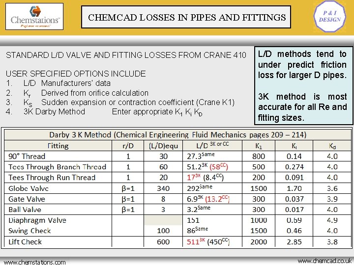
CHEMCAD LOSSES IN PIPES AND FITTINGS STANDARD L/D VALVE AND FITTING LOSSES FROM CRANE 410 USER SPECIFIED OPTIONS INCLUDE 1. L/D Manufacturers’ data 2. Kr Derived from orifice calculation 3. KS Sudden expansion or contraction coefficient (Crane K 1) 4. 3 K Darby Method Enter appropriate K 1 Ki KD www. chemstations. net www. chemstations. com L/D methods tend to under predict friction loss for larger D pipes. 3 K method is most accurate for all Re and fitting sizes. www. chemcad. co. uk
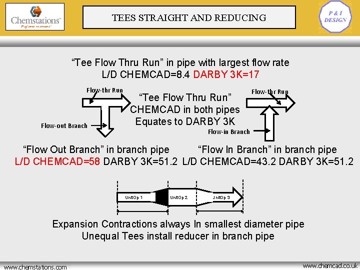
TEES STRAIGHT AND REDUCING “Tee Flow Thru Run” in pipe with largest flow rate L/D CHEMCAD=8. 4 DARBY 3 K=17 Flow-thr Run Flow-out Branch “Tee Flow Thru Run” CHEMCAD in both pipes Equates to DARBY 3 K Flow-thr Run Flow-in Branch “Flow Out Branch” in branch pipe “Flow In Branch” in branch pipe L/D CHEMCAD=58 DARBY 3 K=51. 2 L/D CHEMCAD=43. 2 DARBY 3 K=51. 2 Unit. Op 1 Unit. Op 2 Unit. Op 3 Expansion Contractions always In smallest diameter pipe Unequal Tees install reducer in branch pipe www. chemstations. net www. chemstations. com www. chemcad. co. uk
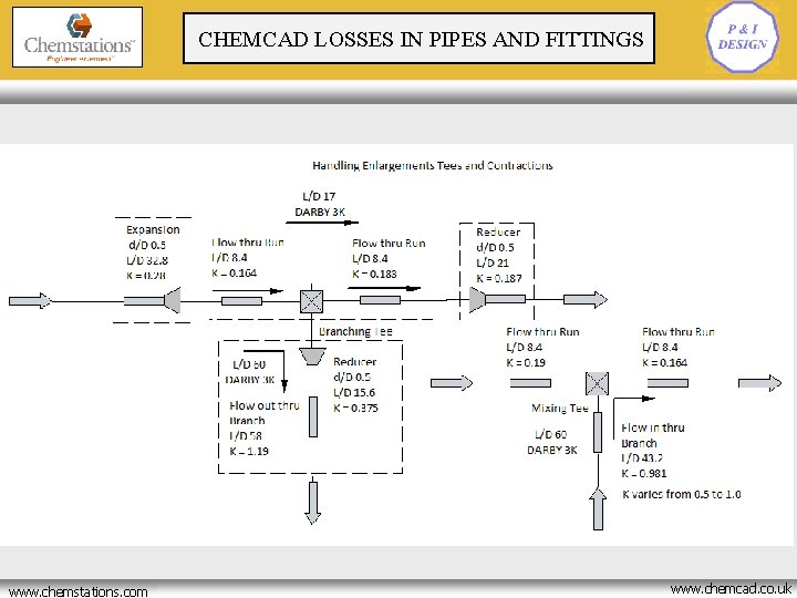
CHEMCAD LOSSES IN PIPES AND FITTINGS www. chemstations. net www. chemstations. com www. chemcad. co. uk
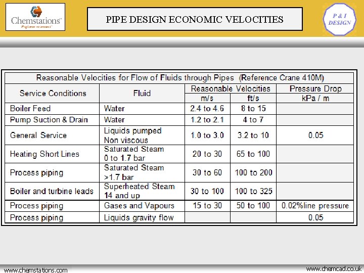
CRYOGENIC BATCH REACTOR PIPE DESIGN ECONOMIC VELOCITIES OPTIMISATION www. chemstations. net www. chemstations. com www. chemcad. co. uk
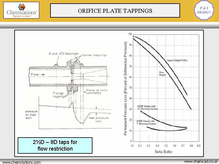
ORIFICE PLATE TAPPINGS 2½D – 8 D taps for flow restriction www. chemstations. net www. chemstations. com www. chemcad. co. uk
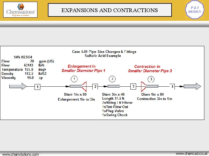
EXPANSIONS AND CONTRACTIONS www. chemstations. net www. chemstations. com www. chemcad. co. uk
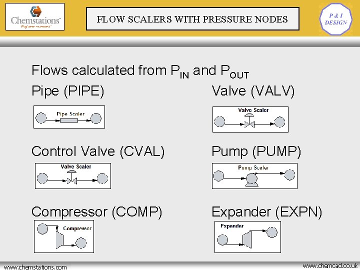
CRYOGENIC BATCH REACTOR FLOW SCALERS WITH PRESSURE NODES OPTIMISATION Flows calculated from PIN and POUT Pipe (PIPE) Valve (VALV) Control Valve (CVAL) Pump (PUMP) Compressor (COMP) Expander (EXPN) www. chemstations. net www. chemstations. com www. chemcad. co. uk
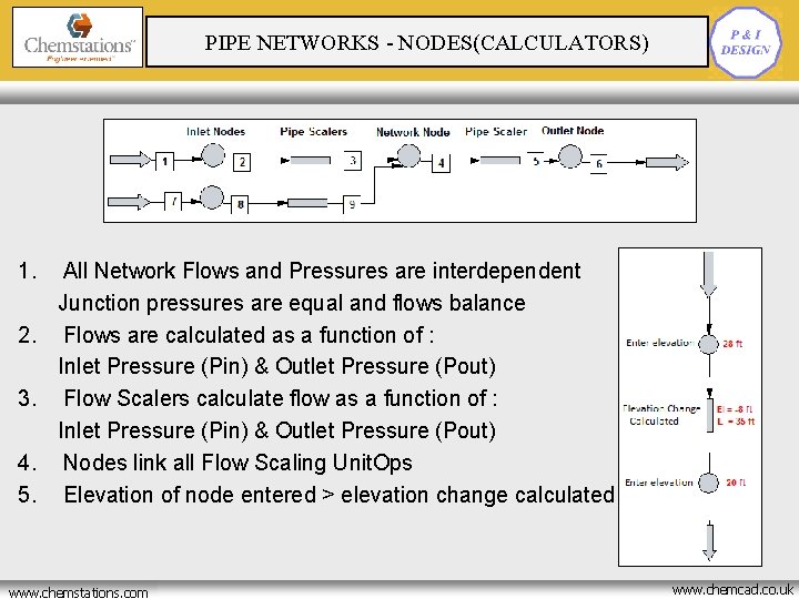
CRYOGENIC BATCH REACTOR PIPE NETWORKS - NODES(CALCULATORS) OPTIMISATION 1. 2. 3. 4. 5. All Network Flows and Pressures are interdependent Junction pressures are equal and flows balance Flows are calculated as a function of : Inlet Pressure (Pin) & Outlet Pressure (Pout) Flow Scalers calculate flow as a function of : Inlet Pressure (Pin) & Outlet Pressure (Pout) Nodes link all Flow Scaling Unit. Ops Elevation of node entered > elevation change calculated www. chemstations. net www. chemstations. com www. chemcad. co. uk
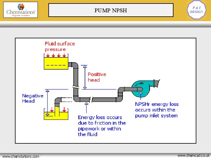
PUMP NPSH www. chemstations. net www. chemstations. com www. chemcad. co. uk
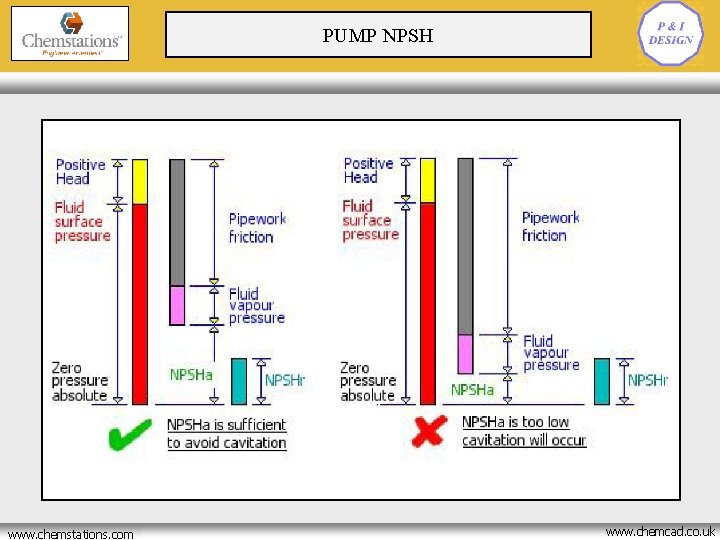
PUMP NPSH www. chemstations. net www. chemstations. com www. chemcad. co. uk
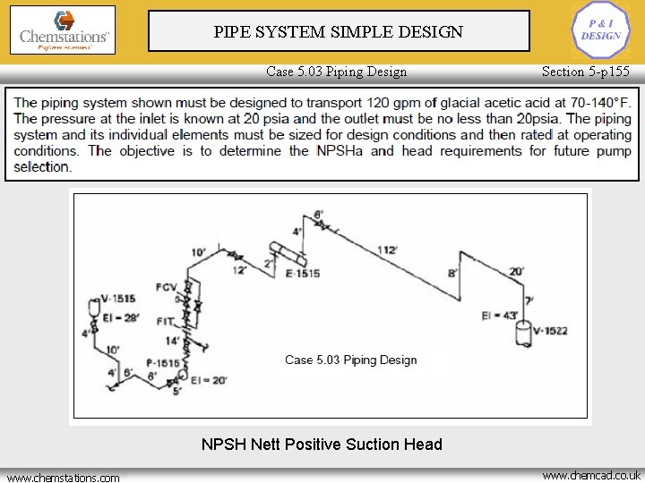
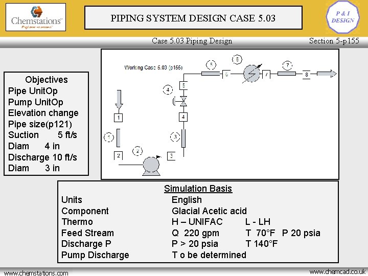
PIPE SYSTEM SIMPLE DESIGN Case 5. 03 Piping Design Section 5 -p 155 NPSH Nett Positive Suction Head www. chemstations. net www. chemstations. com www. chemcad. co. uk
PIPING SYSTEM DESIGN CASE 5. 03 Case 5. 03 Piping Design Section 5 -p 155 Objectives Pipe Unit. Op Pump Unit. Op Elevation change Pipe size(p 121) Suction 5 ft/s Diam 4 in Discharge 10 ft/s Diam 3 in Units Component Thermo Feed Stream Discharge P Pump Discharge www. chemstations. net www. chemstations. com Simulation Basis English Glacial Acetic acid H – UNIFAC L - LH Q 220 gpm T 70°F P 20 psia P > 20 psia T 140°F T o be determined www. chemcad. co. uk
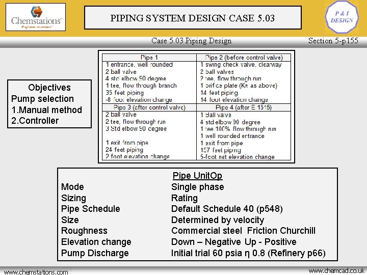
PIPING SYSTEM DESIGN CASE 5. 03 Case 5. 03 Piping Design Section 5 -p 155 Objectives Pump selection 1. Manual method 2. Controller Mode Sizing Pipe Schedule Size Roughness Elevation change Pump Discharge www. chemstations. net www. chemstations. com Pipe Unit. Op Single phase Rating Default Schedule 40 (p 548) Determined by velocity Commercial steel Friction Churchill Down – Negative Up - Positive Initial trial 60 psia η 0. 8 (Refinery p 66) www. chemcad. co. uk
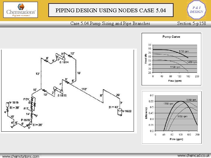
PIPING DESIGN USING NODES CASE 5. 04 Case 5. 04 Pump Sizing and Pipe Branches www. chemstations. net www. chemstations. com Section 5 -p 158 www. chemcad. co. uk
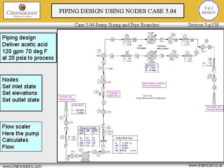
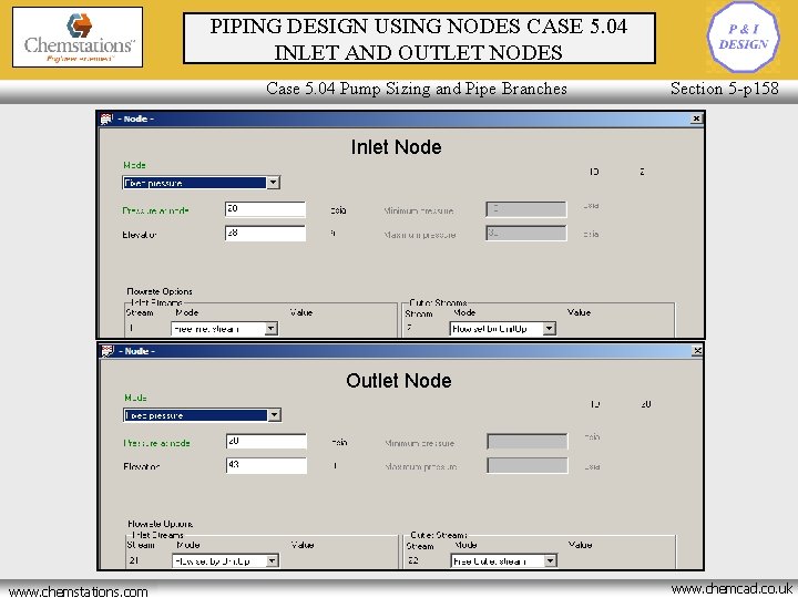
PIPING DESIGN USING NODES CASE 5. 04 Case 5. 04 Pump Sizing and Pipe Branches Section 5 -p 158 Piping design Deliver acetic acid 120 gpm 70 deg F at 20 psia to process Nodes Set inlet state Set elevations Set outlet state Flow scaler Here the pump Calculates Flow www. chemstations. net www. chemstations. com www. chemcad. co. uk
PIPING DESIGN USING NODES CASE 5. 04 INLET AND OUTLET NODES Case 5. 04 Pump Sizing and Pipe Branches Section 5 -p 158 Inlet Node Outlet Node www. chemstations. net www. chemstations. com www. chemcad. co. uk
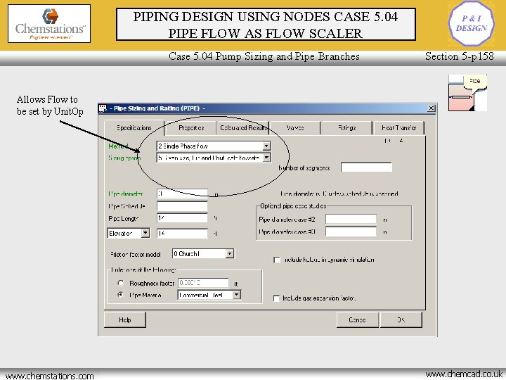
PIPING DESIGN USING NODES CASE 5. 04 PIPE FLOW AS FLOW SCALER Case 5. 04 Pump Sizing and Pipe Branches Section 5 -p 158 Allows Flow to be set by Unit. Op www. chemstations. net www. chemstations. com www. chemcad. co. uk
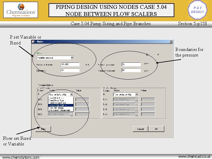
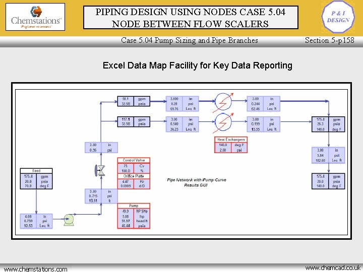
PIPING DESIGN USING NODES CASE 5. 04 NODE BETWEEN FLOW SCALERS Case 5. 04 Pump Sizing and Pipe Branches Section 5 -p 158 P set Variable or Fixed Boundaries for the pressure Flow set Fixed or Variable www. chemstations. net www. chemstations. com www. chemcad. co. uk
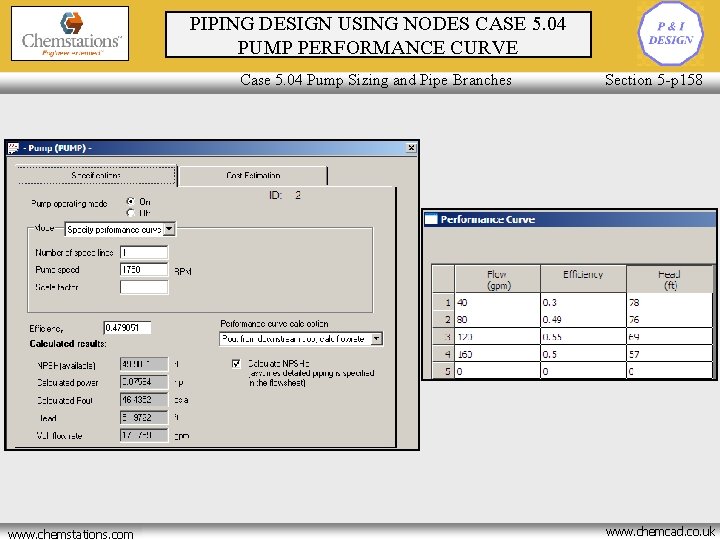
PIPING DESIGN USING NODES CASE 5. 04 PUMP PERFORMANCE CURVE Case 5. 04 Pump Sizing and Pipe Branches www. chemstations. net www. chemstations. com Section 5 -p 158 www. chemcad. co. uk
PIPING DESIGN USING NODES CASE 5. 04 NODE BETWEEN FLOW SCALERS Case 5. 04 Pump Sizing and Pipe Branches Section 5 -p 158 Excel Data Map Facility for Key Data Reporting www. chemstations. net www. chemstations. com www. chemcad. co. uk
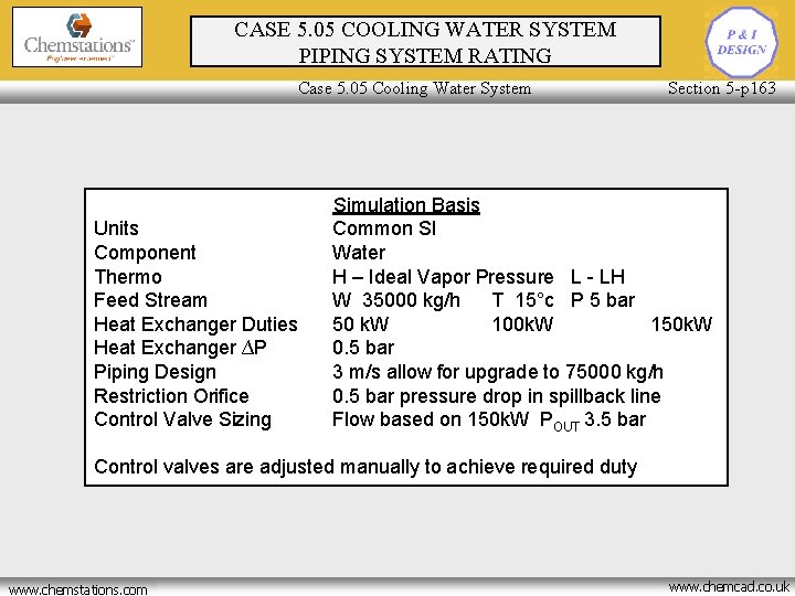
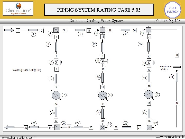
Simulation of more complex piping systems, as found in service distribution networks, to CASE 5. 05 COOLING WATER SYSTEM determine the pressure drops and the flows throughout the system. This case develops Piping Design and Rating PIPING SYSTEM RATING the design of a cooling water distribution system supplying three shell and tube heat Case 5. 05 Cooling Water System Section 5 -p 163 exchangers. Units Component Thermo Feed Stream Heat Exchanger Duties Heat Exchanger ∆P Piping Design Restriction Orifice Control Valve Sizing Simulation Basis Common SI Water H – Ideal Vapor Pressure L - LH W 35000 kg/h T 15°c P 5 bar 50 k. W 100 k. W 150 k. W 0. 5 bar 3 m/s allow for upgrade to 75000 kg/h 0. 5 bar pressure drop in spillback line Flow based on 150 k. W POUT 3. 5 bar Control valves are adjusted manually to achieve required duty www. chemstations. net www. chemstations. com www. chemcad. co. uk
PIPING SYSTEM RATING CASE 5. 05 Piping Design and Rating Case 5. 05 Cooling Water System www. chemstations. net www. chemstations. com Section 5 -p 163 www. chemcad. co. uk
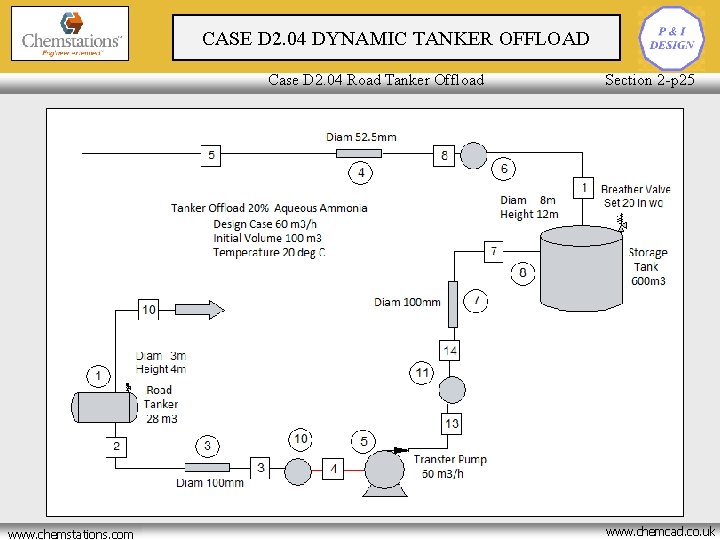
CASE D 2. 04 DYNAMIC TANKER OFFLOAD Piping Design and Rating Case D 2. 04 Road Tanker Offload www. chemstations. net www. chemstations. com Section 2 -p 25 www. chemcad. co. uk
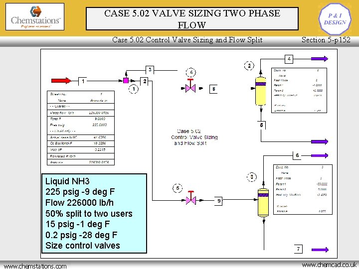
CASE 5. 02 VALVE SIZING TWO PHASE Piping Design and Rating FLOW Case 5. 02 Control Valve Sizing and Flow Split Section 5 -p 152 Liquid NH 3 225 psig -9 deg F Flow 226000 lb/h 50% split to two users 15 psig -1 deg F 0. 2 psig -28 deg F Size control valves www. chemstations. net www. chemstations. com www. chemcad. co. uk