
Characterization of a lumped getter pump SAES Capaci


- Slides: 23
Characterization of a lumped getter pump: SAES Capaci. Torr A. Michet TE/VSC/IVM 1
Outline 1. Some notions about non-evaporable getters (NEG) 1. 1 Pumping process 1. 2 Activation / reconditioning process 1. 3 Capaci. Torr 1300 2. Pumping speed measurements 2. 1 Test bench 2. 2 Measurements for selected gas species 3. Ultimate vacuum measurements 3. 1 Test bench 3. 2 Unbaked system 3. 3 Baked system 4. Performance tests 4. 1 Presentation 4. 2 Test bench 4. 3 Hydrogen injections 4. 4 Calculations about reconditioning 4. 5 1 st reconditioning 4. 6 2 nd reconditioning 2
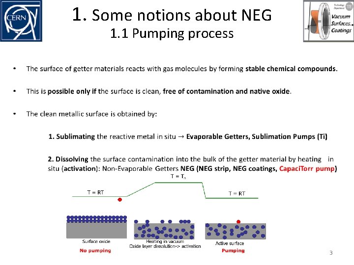
1. Some notions about NEG 1. 1 Pumping process • 3
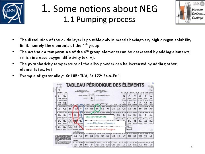
1. Some notions about NEG 1. 1 Pumping process • • The dissolution of the oxide layer is possible only in metals having very high oxygen solubility limit, namely the elements of the 4 th group. The activation temperature of the 4 th group elements can be decreased by adding elements which increase oxygen diffusivity (ex: V). The pyrophoricity temperature of the alloy powder can be increased by adding other elements (ex: Fe) Example of getter alloy: St 185: Ti-V, St 172: Zr-V-Fe ) 4
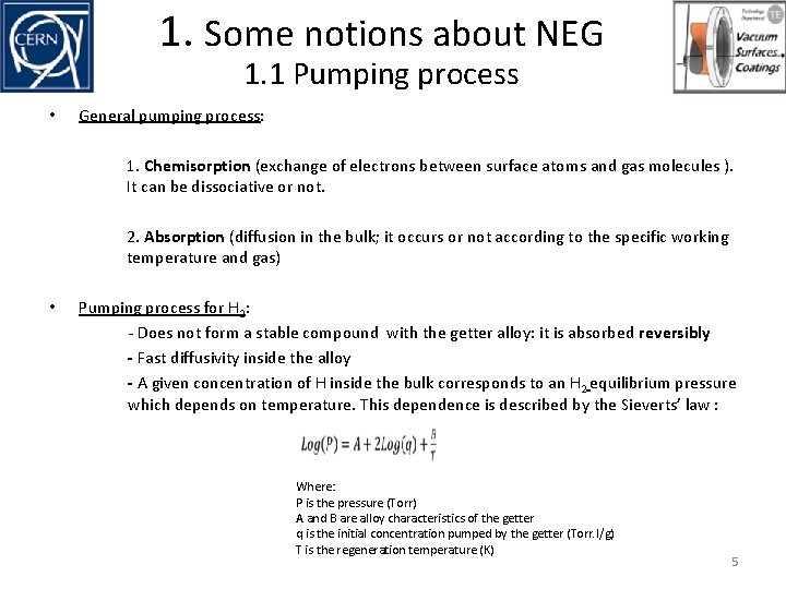
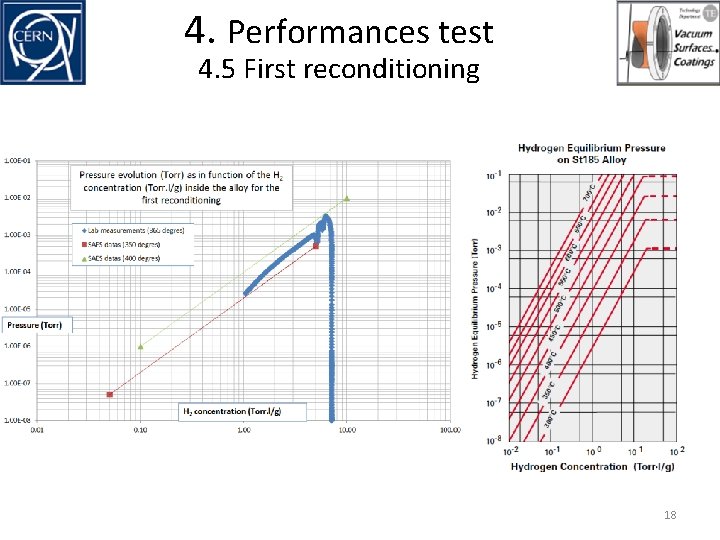
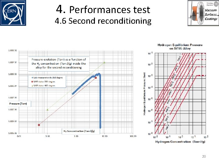
1. Some notions about NEG 1. 1 Pumping process • General pumping process: 1. Chemisorption (exchange of electrons between surface atoms and gas molecules ). It can be dissociative or not. 2. Absorption (diffusion in the bulk; it occurs or not according to the specific working temperature and gas) • Pumping process for H 2: - Does not form a stable compound with the getter alloy: it is absorbed reversibly - Fast diffusivity inside the alloy - A given concentration of H inside the bulk corresponds to an H 2 equilibrium pressure which depends on temperature. This dependence is described by the Sieverts’ law : Where: P is the pressure (Torr) A and B are alloy characteristics of the getter q is the initial concentration pumped by the getter (Torr. l/g) T is the regeneration temperature (K) 5
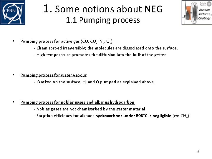
1. Some notions about NEG 1. 1 Pumping process • Pumping process for active gas (CO, CO 2, N 2, O 2) - Chemisorbed irreversibly; the molecules are dissociated onto the surface. - High temperature promotes the diffusion into the bulk of the getter • Pumping process for water vapour - Cracked on the surface: H, and O pumped as explained above • Pumping process for nobles gases and alkanes hydrocarbon - Nobles gases are not chemisorbed by the getter material - Sorption efficiency for alkanes hydrocarbons under 500°C is negligible (ex: CH 4) 6
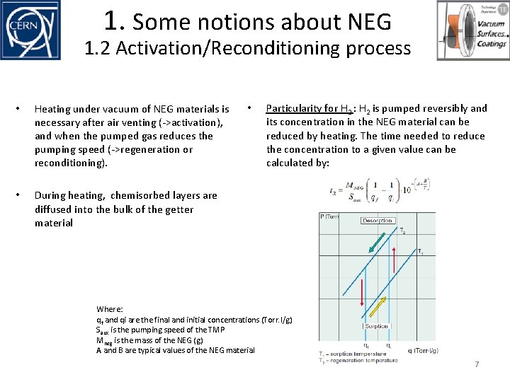
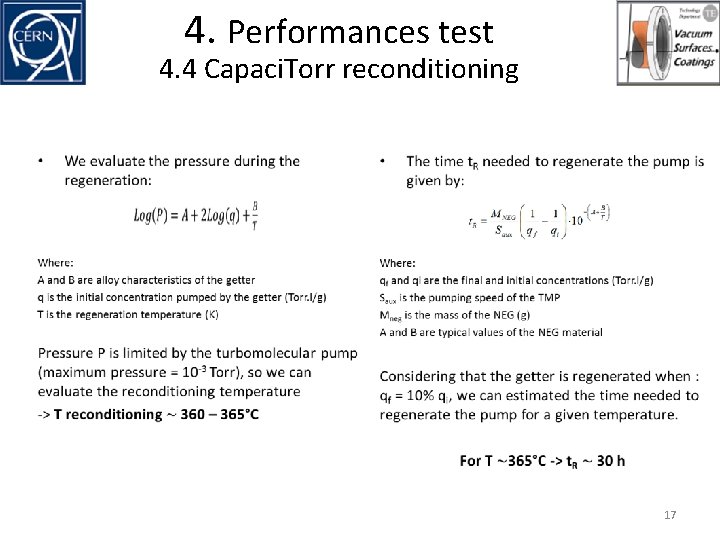
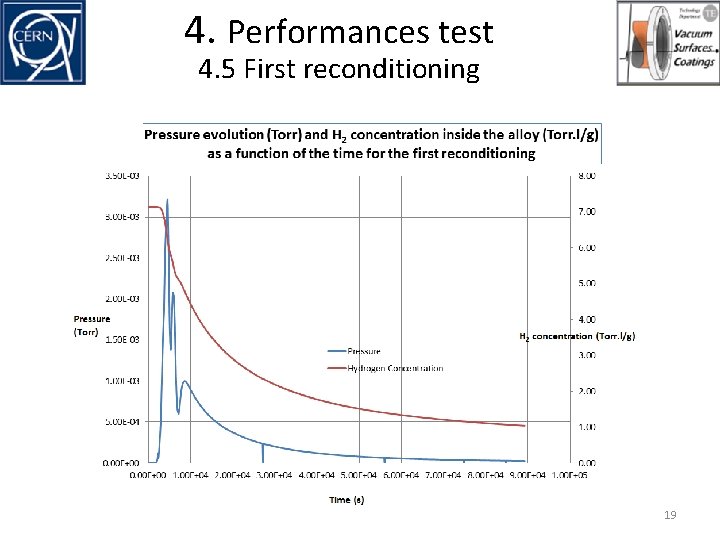
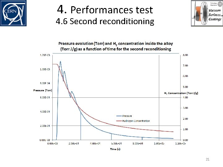
1. Some notions about NEG 1. 2 Activation/Reconditioning process • Heating under vacuum of NEG materials is necessary after air venting (->activation), and when the pumped gas reduces the pumping speed (->regeneration or reconditioning). • During heating, chemisorbed layers are diffused into the bulk of the getter material • Particularity for H 2 : H 2 is pumped reversibly and its concentration in the NEG material can be reduced by heating. The time needed to reduce the concentration to a given value can be calculated by: Where: qf and qi are the final and initial concentrations (Torr. l/g) Saux is the pumping speed of the TMP Mneg is the mass of the NEG (g) A and B are typical values of the NEG material 7
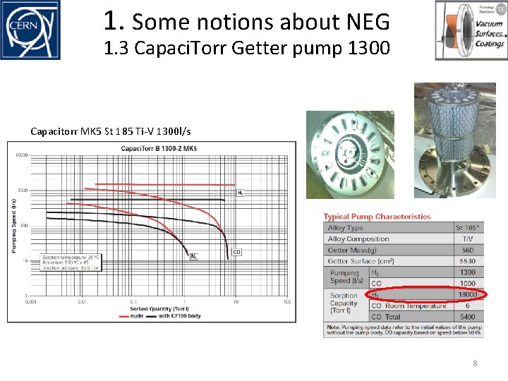
1. Some notions about NEG 1. 3 Capaci. Torr Getter pump 1300 Capacitorr MK 5 St 185 Ti-V 1300 l/s 8
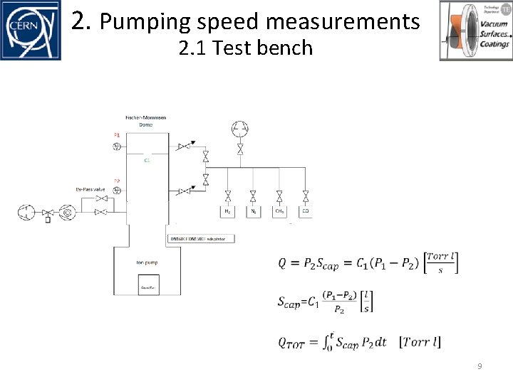
2. Pumping speed measurements 2. 1 Test bench 9
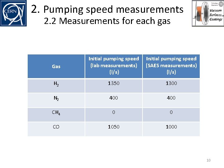
2. Pumping speed measurements 2. 2 Measurements for each gas Gas Initial pumping speed (lab measurements) (l/s) Initial pumping speed (SAES measurements) (l/s) H 2 1350 1300 N 2 400 CH 4 0 0 CO 1050 1000 10
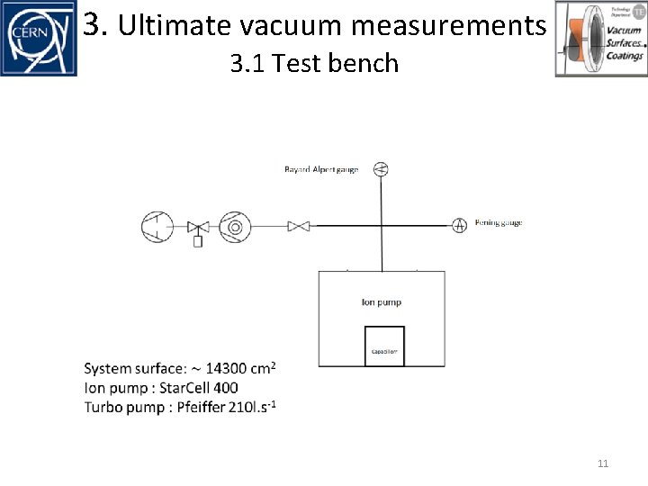
3. Ultimate vacuum measurements 3. 1 Test bench 11
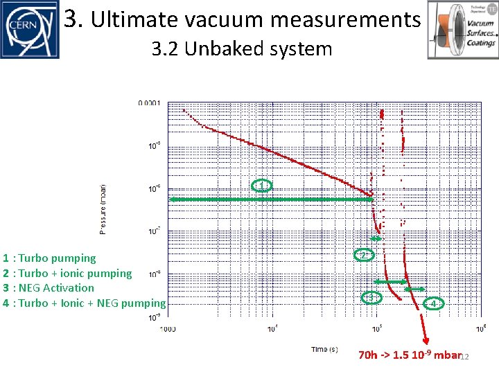
3. Ultimate vacuum measurements 3. 2 Unbaked system 1 1 : Turbo pumping 2 : Turbo + ionic pumping 3 : NEG Activation 4 : Turbo + Ionic + NEG pumping 2 3 4 70 h -> 1. 5 10 -9 mbar 12
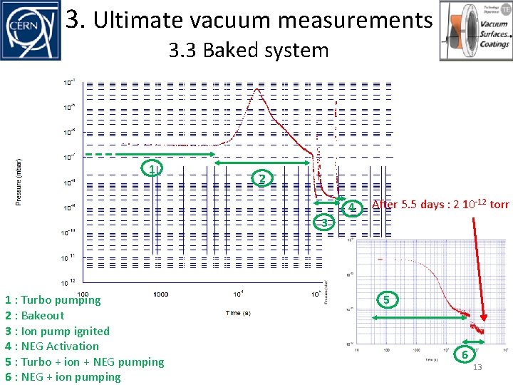
3. Ultimate vacuum measurements 3. 3 Baked system 1 2 3 1 : Turbo pumping 2 : Bakeout 3 : Ion pump ignited 4 : NEG Activation 5 : Turbo + ion + NEG pumping 6 : NEG + ion pumping 4 After 5. 5 days : 2 10 -12 torr 5 6 13
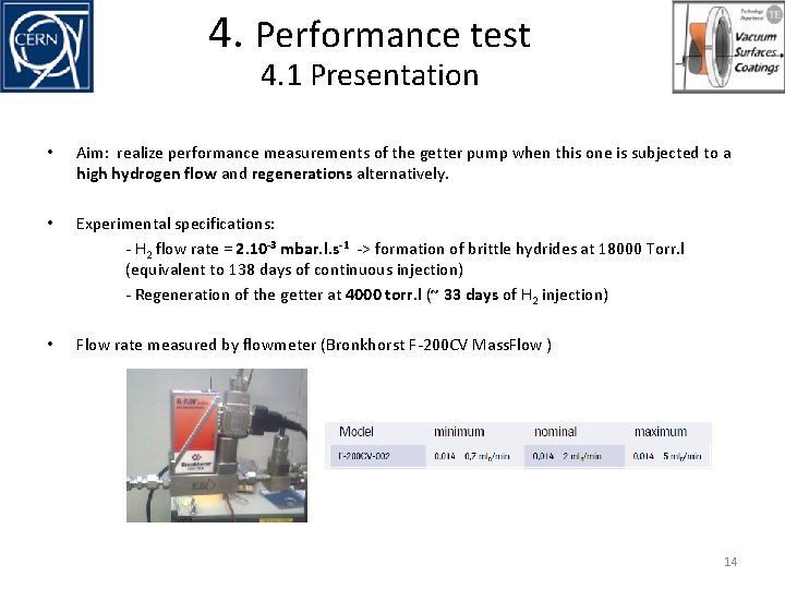
4. Performance test 4. 1 Presentation • Aim: realize performance measurements of the getter pump when this one is subjected to a high hydrogen flow and regenerations alternatively. • Experimental specifications: - H 2 flow rate = 2. 10 -3 mbar. l. s-1 -> formation of brittle hydrides at 18000 Torr. l (equivalent to 138 days of continuous injection) - Regeneration of the getter at 4000 torr. l (~ 33 days of H 2 injection) • Flow rate measured by flowmeter (Bronkhorst F-200 CV Mass. Flow ) 14
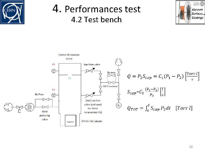
4. Performances test 4. 2 Test bench 15
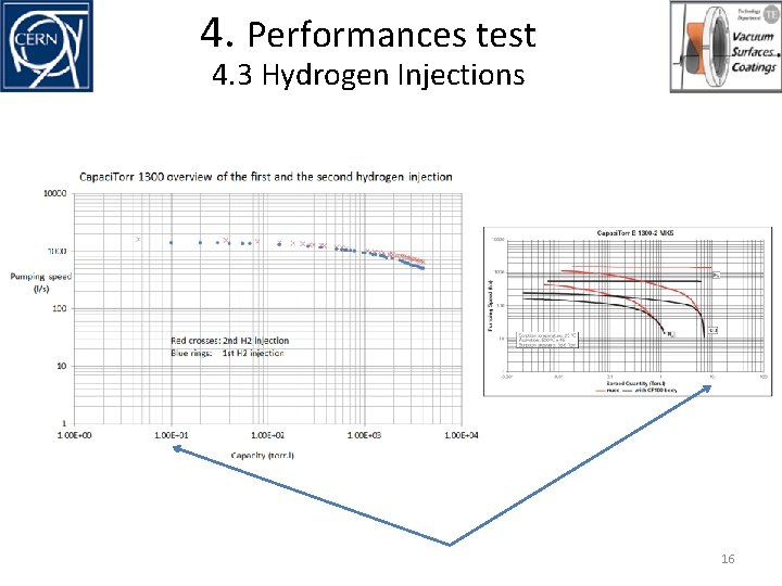
4. Performances test 4. 3 Hydrogen Injections 16
4. Performances test 4. 4 Capaci. Torr reconditioning • 17
4. Performances test 4. 5 First reconditioning 18
4. Performances test 4. 5 First reconditioning 19
4. Performances test 4. 6 Second reconditioning 20
4. Performances test 4. 6 Second reconditioning 21
Conclusion • Measurements still ongoing The Capaci. Torr pumps : - reach very low pressures - work with high flow of hydrogen ( be careful with H 2 sorption limit : necessity of reconditioning) • • Regenerations' laws are known and reproducible • We are more confident with this type of pump (application on linac 4 in the future) • The Ti-V alloy is not made anymore (environmental problems during production of powders). • The Capaci. Torr 2000, based on Zr-V-Fe are installed on Linac 4. The hydrogen embrittlement limit is lower than Ti-V (4500 against 18000 Torr l, but the quantity of NEG material can be increased) • Next step in collaboration with SAES : test of the Capaci. Torr 2000 with a fourfold quantity of NEG material. 22
Thanks for your attention ! 23