
Characteristics of an Economically Attractive Fusion Power Plant
- Slides: 24
Characteristics of an Economically Attractive Fusion Power Plant Farrokh Najmabadi University of California San Diego Fusion: Energy Source for the Future? AAAS Annual Meeting February 19, 2005 Electronic copy: http: //aries. ucsd. edu/najmabadi/ ARIES Web Site: http: /aries. ucsd. edu/ARIES
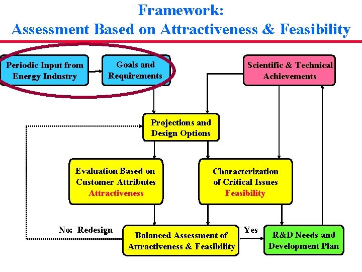
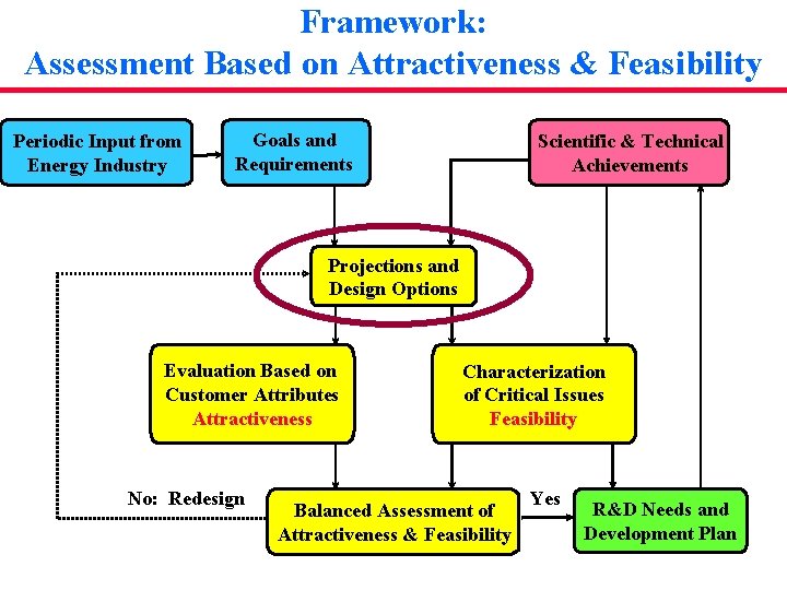
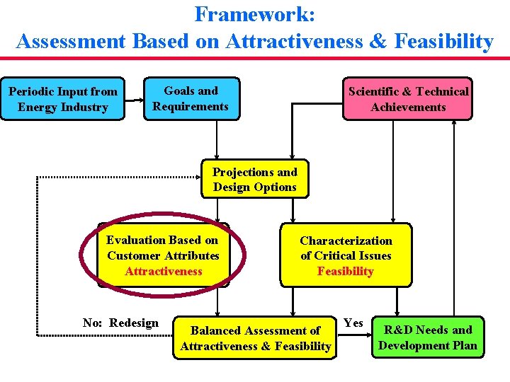
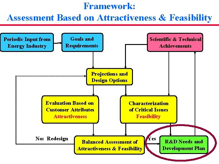
Framework: Assessment Based on Attractiveness & Feasibility Periodic Input from Energy Industry Goals and Requirements Scientific & Technical Achievements Projections and Design Options Evaluation Based on Customer Attributes Attractiveness No: Redesign Characterization of Critical Issues Feasibility Balanced Assessment of Attractiveness & Feasibility Yes R&D Needs and Development Plan
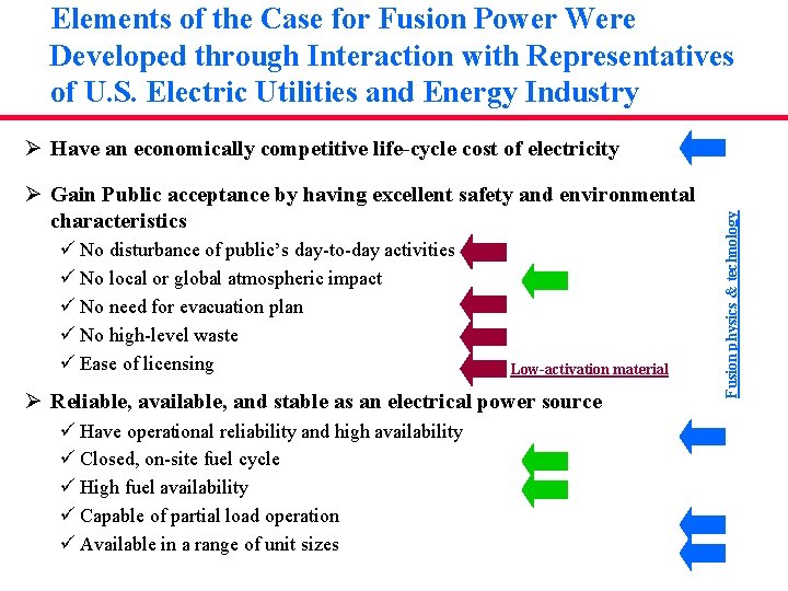
Elements of the Case for Fusion Power Were Developed through Interaction with Representatives of U. S. Electric Utilities and Energy Industry Ø Gain Public acceptance by having excellent safety and environmental characteristics ü No disturbance of public’s day-to-day activities ü No local or global atmospheric impact ü No need for evacuation plan ü No high-level waste ü Ease of licensing Low-activation material Ø Reliable, available, and stable as an electrical power source ü Have operational reliability and high availability ü Closed, on-site fuel cycle ü High fuel availability ü Capable of partial load operation ü Available in a range of unit sizes Fusion physics & technology Ø Have an economically competitive life-cycle cost of electricity
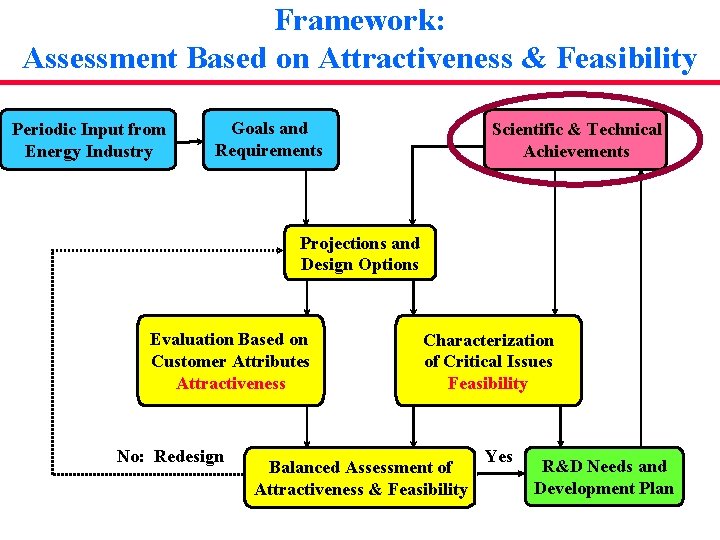
Framework: Assessment Based on Attractiveness & Feasibility Periodic Input from Energy Industry Goals and Requirements Scientific & Technical Achievements Projections and Design Options Evaluation Based on Customer Attributes Attractiveness No: Redesign Characterization of Critical Issues Feasibility Balanced Assessment of Attractiveness & Feasibility Yes R&D Needs and Development Plan
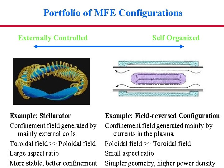
Portfolio of MFE Configurations Externally Controlled Example: Stellarator Confinement field generated by mainly external coils Toroidal field >> Poloidal field Large aspect ratio More stable, better confinement Self Organized Example: Field-reversed Configuration Confinement field generated mainly by currents in the plasma Poloidal field >> Toroidal field Small aspect ratio Simpler geometry, higher power density
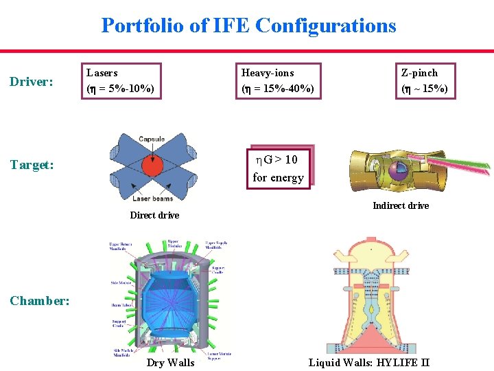
Portfolio of IFE Configurations Driver: Lasers (h = 5%-10%) Heavy-ions (h = 15%-40%) Z-pinch (h ~ 15%) h. G > 10 for energy Target: Direct drive Indirect drive Chamber: Dry Walls Liquid Walls: HYLIFE II
Framework: Assessment Based on Attractiveness & Feasibility Periodic Input from Energy Industry Goals and Requirements Scientific & Technical Achievements Projections and Design Options Evaluation Based on Customer Attributes Attractiveness No: Redesign Characterization of Critical Issues Feasibility Balanced Assessment of Attractiveness & Feasibility Yes R&D Needs and Development Plan
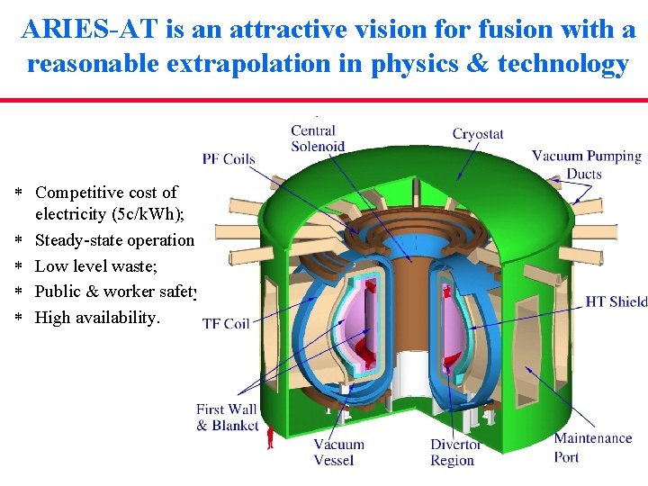
ARIES-AT is an attractive vision for fusion with a reasonable extrapolation in physics & technology * Competitive cost of electricity (5 c/k. Wh); * Steady-state operation; * Low level waste; * Public & worker safety; * High availability.
A high-performance plasma should have a high power density & a low recirculating power fraction Requirement: Establish and maintain the magnetic bottle Ø External magnets: ü Superconducting: size and cost ü Normal conducting (e. g. , copper): power consumption Ø Maintenance of plasma profiles (mainly plasma current) ü Inductive (transformer action): non-stationary ü Non-inductive through Neutral beams, microwave, …: Inefficient ØKey parameters: ü Plasma b (ratio of plasma pressure to magnetic pressure) Non-dimensional parameter b. N is a measure of plasma performance ü Current-drive power PCD
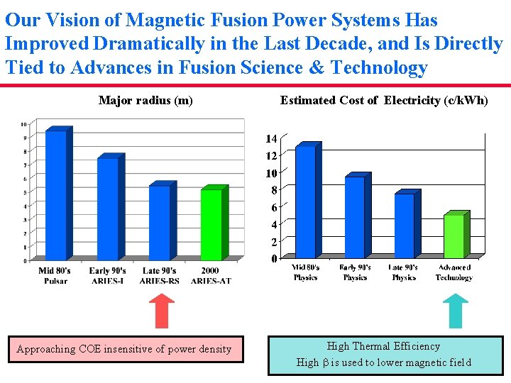
A dramatic change occurred in 1990: Introduction of Advanced Tokamak Ø Our vision of a fusion system in 1980 s was a large pulsed device. ü Non-inductive current drive is inefficient. Ø Some important achievements in 1980 s: ü Experimental demonstration of bootstrap current; ü Development of ideal MHD codes that agreed with experimental results. ü Development of steady-state power plant concepts (ARIES-I and SSTR) based on the trade-off of bootstrap current fraction and plasma b ARIES-I: b. N= 2. 9, b=2%, Pcd=230 MW Reverse Shear Regime Ø Excellent match between bootstrap & equilibrium current profile at high b. Ø ARIES-RS (medium extrapolation): b. N= 4. 8, b=5%, Pcd=81 MW (achieves ~5 MW/m 2 peak wall loading. ) Ø ARIES-AT (aggressive extrapolation): b. N= 5. 4, b=9%, Pcd=36 MW (high b is used to reduce peak field at magnet)
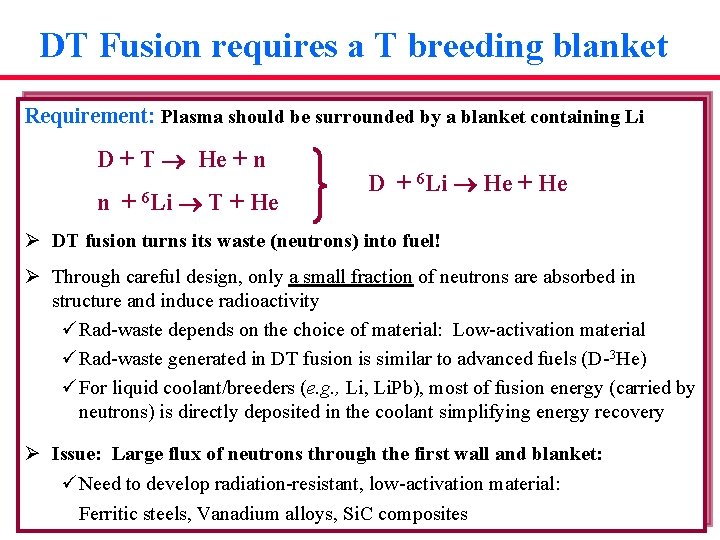
DT Fusion requires a T breeding blanket Requirement: Plasma should be surrounded by a blanket containing Li D + T He + n n + 6 Li T + He D + 6 Li He + He Ø DT fusion turns its waste (neutrons) into fuel! Ø Through careful design, only a small fraction of neutrons are absorbed in structure and induce radioactivity ü Rad-waste depends on the choice of material: Low-activation material ü Rad-waste generated in DT fusion is similar to advanced fuels (D-3 He) ü For liquid coolant/breeders (e. g. , Li. Pb), most of fusion energy (carried by neutrons) is directly deposited in the coolant simplifying energy recovery Ø Issue: Large flux of neutrons through the first wall and blanket: ü Need to develop radiation-resistant, low-activation material: Ferritic steels, Vanadium alloys, Si. C composites
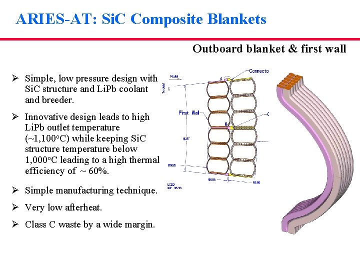
ARIES-AT: Si. C Composite Blankets Outboard blanket & first wall Ø Simple, low pressure design with Si. C structure and Li. Pb coolant and breeder. Ø Innovative design leads to high Li. Pb outlet temperature (~1, 100 o. C) while keeping Si. C structure temperature below 1, 000 o. C leading to a high thermal efficiency of ~ 60%. Ø Simple manufacturing technique. Ø Very low afterheat. Ø Class C waste by a wide margin.
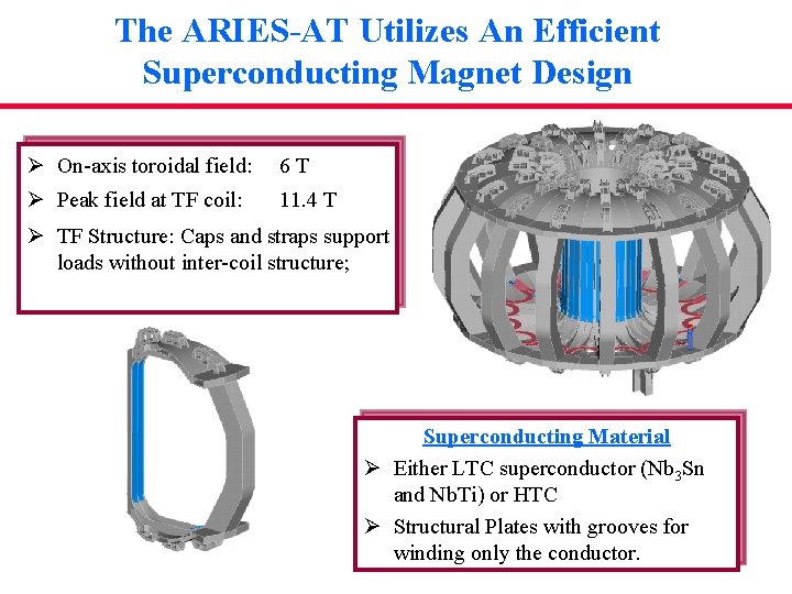
The ARIES-AT Utilizes An Efficient Superconducting Magnet Design Ø On-axis toroidal field: 6 T Ø Peak field at TF coil: 11. 4 T Ø TF Structure: Caps and straps support loads without inter-coil structure; Superconducting Material Ø Either LTC superconductor (Nb 3 Sn and Nb. Ti) or HTC Ø Structural Plates with grooves for winding only the conductor.
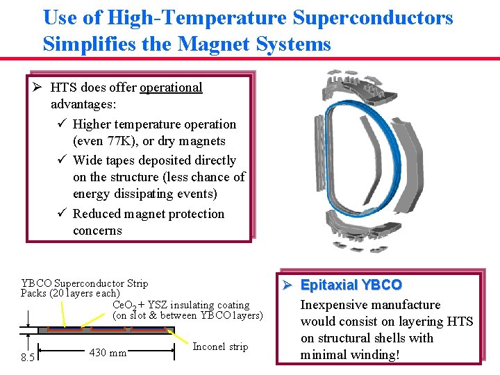
Use of High-Temperature Superconductors Simplifies the Magnet Systems Ø HTS does offer operational advantages: ü Higher temperature operation (even 77 K), or dry magnets ü Wide tapes deposited directly on the structure (less chance of energy dissipating events) ü Reduced magnet protection concerns YBCO Superconductor Strip Packs (20 layers each) Ce. O 2 + YSZ insulating coating (on slot & between YBCO layers) 8. 5 430 mm Inconel strip Ø Epitaxial YBCO Inexpensive manufacture would consist on layering HTS on structural shells with minimal winding!
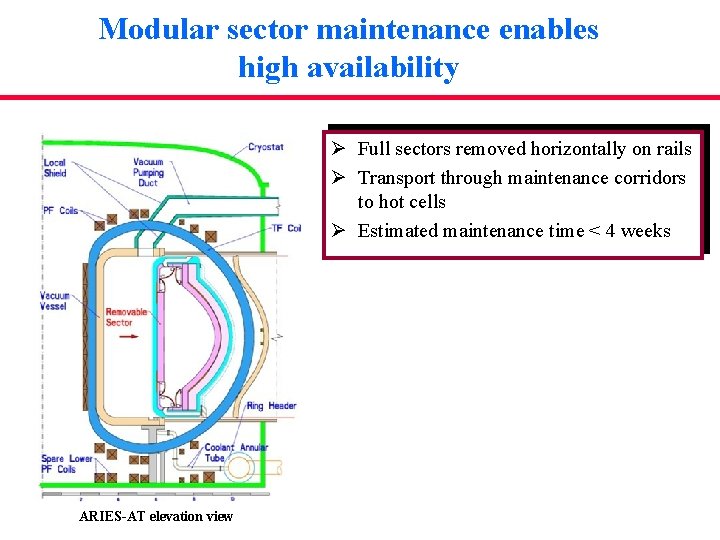
Modular sector maintenance enables high availability Ø Full sectors removed horizontally on rails Ø Transport through maintenance corridors to hot cells Ø Estimated maintenance time < 4 weeks ARIES-AT elevation view
Framework: Assessment Based on Attractiveness & Feasibility Periodic Input from Energy Industry Goals and Requirements Scientific & Technical Achievements Projections and Design Options Evaluation Based on Customer Attributes Attractiveness No: Redesign Characterization of Critical Issues Feasibility Balanced Assessment of Attractiveness & Feasibility Yes R&D Needs and Development Plan
Our Vision of Magnetic Fusion Power Systems Has Improved Dramatically in the Last Decade, and Is Directly Tied to Advances in Fusion Science & Technology Major radius (m) Approaching COE insensitive of power density Estimated Cost of Electricity (c/k. Wh) High Thermal Efficiency High b is used to lower magnetic field
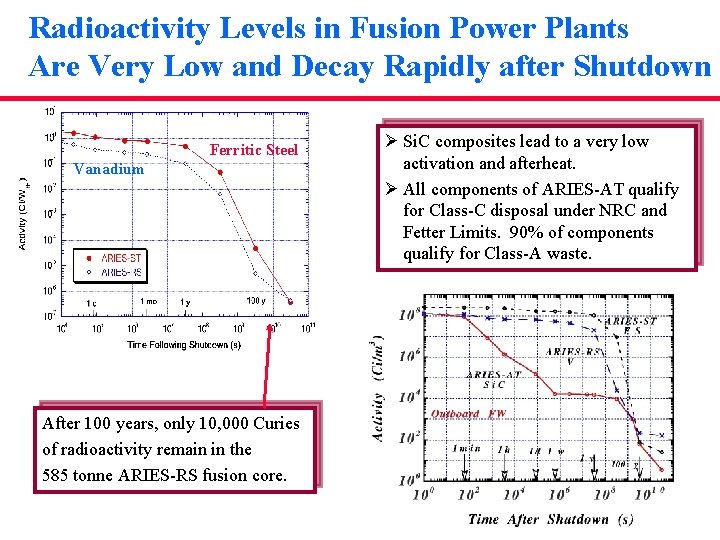
Radioactivity Levels in Fusion Power Plants Are Very Low and Decay Rapidly after Shutdown Ferritic Steel Vanadium After 100 years, only 10, 000 Curies of radioactivity remain in the 585 tonne ARIES-RS fusion core. Ø Si. C composites lead to a very low activation and afterheat. Ø All components of ARIES-AT qualify for Class-C disposal under NRC and Fetter Limits. 90% of components qualify for Class-A waste.
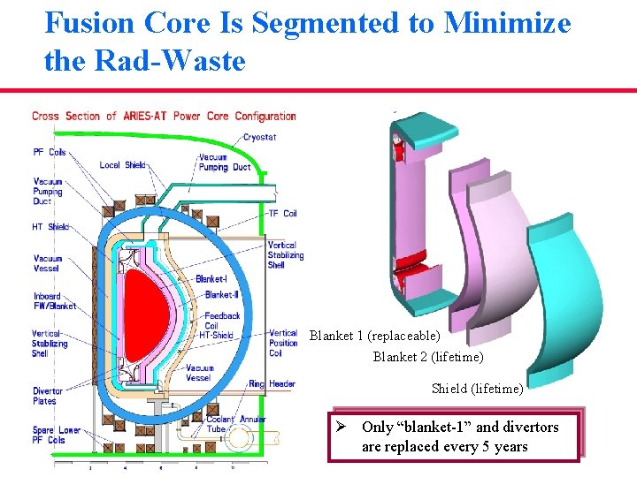
Fusion Core Is Segmented to Minimize the Rad-Waste Blanket 1 (replaceable) Blanket 2 (lifetime) Shield (lifetime) Ø Only “blanket-1” and divertors are replaced every 5 years
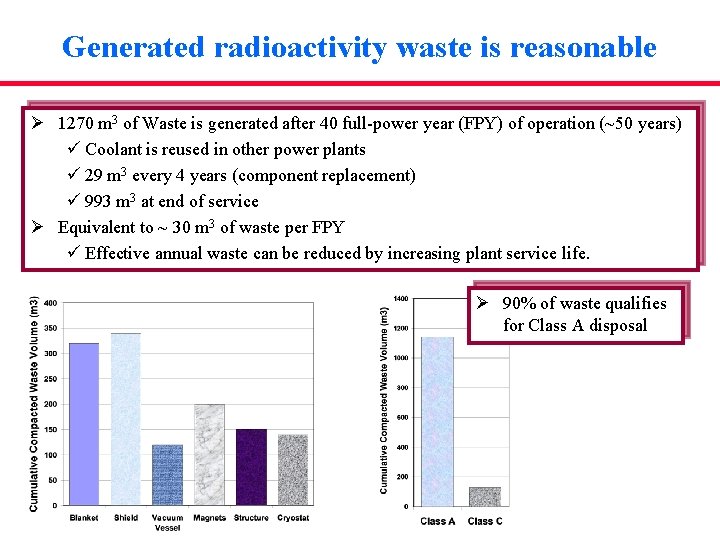
Generated radioactivity waste is reasonable Ø 1270 m 3 of Waste is generated after 40 full-power year (FPY) of operation (~50 years) ü Coolant is reused in other power plants ü 29 m 3 every 4 years (component replacement) ü 993 m 3 at end of service Ø Equivalent to ~ 30 m 3 of waste per FPY ü Effective annual waste can be reduced by increasing plant service life. Ø 90% of waste qualifies for Class A disposal
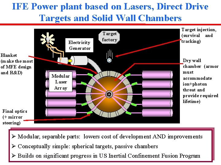
IFE Power plant based on Lasers, Direct Drive Targets and Solid Wall Chambers Electricity Generator Blanket (make the most of MFE design and R&D) Target factory Modular Laser Array Target injection, (survival and tracking) Dry wall chamber (armor must accommodate ion+photon threat and provide required lifetime) Final optics (+ mirror steering) Ø Modular, separable parts: lowers cost of development AND improvements Ø Conceptually simple: spherical targets, passive chambers Ø Builds on significant progress in US Inertial Confinement Fusion Program
Framework: Assessment Based on Attractiveness & Feasibility Periodic Input from Energy Industry Goals and Requirements Scientific & Technical Achievements Projections and Design Options Evaluation Based on Customer Attributes Attractiveness No: Redesign Characterization of Critical Issues Feasibility Balanced Assessment of Attractiveness & Feasibility Yes R&D Needs and Development Plan
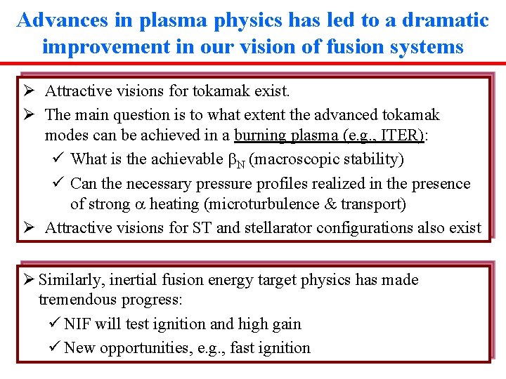
Advances in plasma physics has led to a dramatic improvement in our vision of fusion systems Ø Attractive visions for tokamak exist. Ø The main question is to what extent the advanced tokamak modes can be achieved in a burning plasma (e. g. , ITER): ü What is the achievable b. N (macroscopic stability) ü Can the necessary pressure profiles realized in the presence of strong a heating (microturbulence & transport) Ø Attractive visions for ST and stellarator configurations also exist Ø Similarly, inertial fusion energy target physics has made tremendous progress: ü NIF will test ignition and high gain ü New opportunities, e. g. , fast ignition
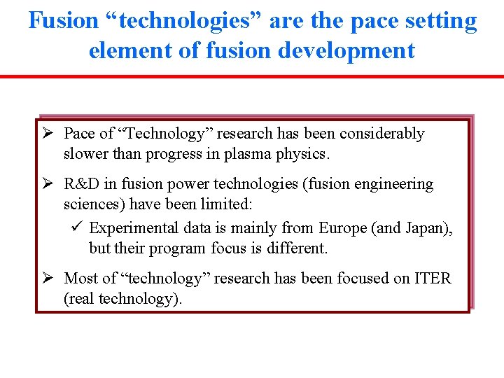
Fusion “technologies” are the pace setting element of fusion development Ø Pace of “Technology” research has been considerably slower than progress in plasma physics. Ø R&D in fusion power technologies (fusion engineering sciences) have been limited: ü Experimental data is mainly from Europe (and Japan), but their program focus is different. Ø Most of “technology” research has been focused on ITER (real technology).