Chapter4 Pulse Modulation Techniques Introduction to Communication Systems
 Mr. Haneef Khan")
 and Pulse Modulation techniques. 2. Differentiate pulse analog and")


 �PAM is defined as the process of varying the amplitude")
 =")


 �PWM is defined as the process of varying the width")

 �PPM is defined as the process of varying the")


 � PCM is used to digitally represent sampled analog signals.")


 �Delta Modulation is obtained by simplifying the quantization and encoding process")


- Slides: 25
Chapter-4 Pulse Modulation Techniques Introduction to Communication Systems (CNET - 222) Mr. Haneef Khan Department of Computer Networks College of CS&IS Jazan University, Jazan.
Objectives 1. Differentiate CW(continuous wave) and Pulse Modulation techniques. 2. Differentiate pulse analog and digital modulation techniques. 3. Define PAM, PWM, PPM, PCM and DM 4. Describe Sampling process 5. Describe Nyquist Theorm
Introduction �In previous chapters, we studied about the Analog Modulation techniques, Sine wave is used as the carrier signal. �In Pulse Modulation techniques, sine wave will be replaced by the Pulse train. As the sine wave being characterized in term of its parameters (amplitude, frequency, and phase) , the pulse train is also characterized in the same way.
Pulse Modulation Classification Pulse Modulation is further classified into two categories depending on whether the parameter of the pulse is continuous and discrete in nature: 1. Pulse Analog Modulation Techniques 2. Pulse Digital Modulation Techniques
Pulse Analog Modulation Techniques The pulse Modulation techniques are of three types namely: 1. Pulse Amplitude Modulation(PAM) 2. Pulse Width Modulation(PWM) 3. Pulse Position Modulation (PPM) In all above techniques, message signal will be Analog and Carrier signal will be pulse. Now, We will Elaborate all the techniques one by one.
1. Pulse Amplitude Modulation(PAM) �PAM is defined as the process of varying the amplitude of the pulse in accordance to the instantaneous value of the message signal. �Message Signal is given by, v m = Vm sin(ωm t) �Carrier signal or Pulse train is given by, p = Vp 0≤t≤Δ = 0 0 ≤ t ≤ T 0
Pulse amplitude modulated signal is given by, pa = Vp Vm sin(ωm t) = 0 0≤t≤Δ 0 ≤ t ≤ T 0
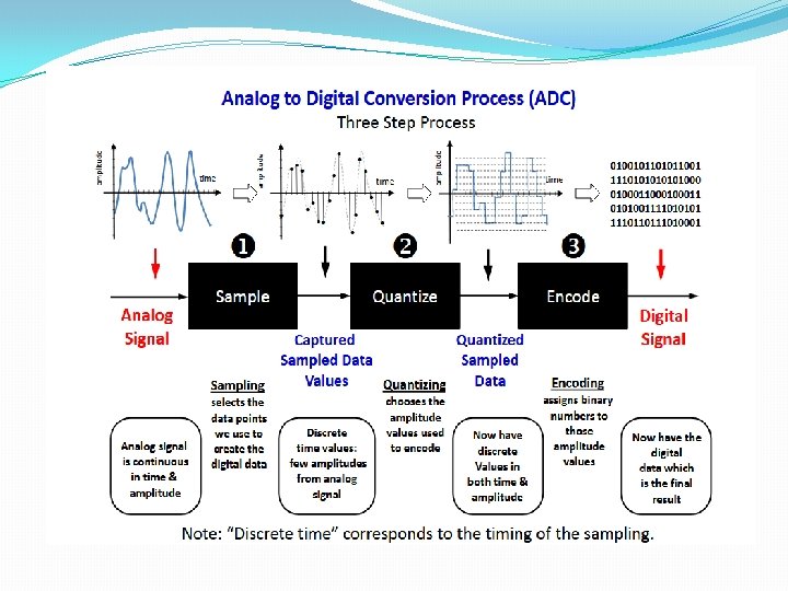
Sampling Process �Sampling is a signal processing operation that helps is sensing the continuous time signal values at discrete instants of time. �Sampled signal will have amplitudes equal to signal values at the sampling instants and undefined at all other times. �Sampling theorem is important because it allows a continuous signal to be sampled and then transmitted as a discrete number rather than a continuous time signal. Processing a continuous signal is then equivalent to processing a discrete signal.
Nyquist frequency and Nyquist rate �Nyquist frequency is the maximum frequency in a signal that can be well recorded given a certain sampling rate. �Nyquist rate is the sampling rate needed to record signal well given a certain maximum frequency in a signal. �Nyquist rate = Given max frequency x 2
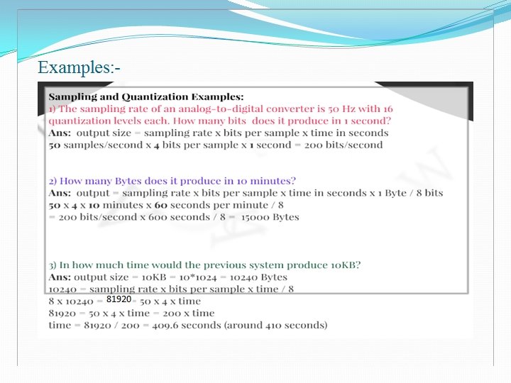
Examples: -
2. Pulse Width Modulation(PWM) �PWM is defined as the process of varying the width of the pulse in accordance to the instantaneous value of the message signal. �Message Signal is given by, v m = Vm sin(ωm t) �Carrier signal or Pulse train is given by, p = Vp 0≤t≤Δ = 0 0 ≤ t ≤ T 0 �Carrier signal width is given by, Δ α vm
The width of pulse in PWM signal is given by, Δm = Δ(1+ vm )
3. Pulse Position Modulation (PPM) �PPM is defined as the process of varying the position of the pulse in accordance to the instantaneous value of the message signal. �Message Signal is given by, v m = Vm sin(ωm t) �Carrier signal or Pulse train is given by, p = Vp 0≤t≤Δ = 0 0 ≤ t ≤ T 0
• Let tp indicates the timing instant of the leading or trailing edge of the pulse in each period of the pulse train. In PPM t p α vm • The Position of the leading pr trailing edge of the pulse in PPM signal is given by, tp = f(vm)
PWM And PPM Modulated Signal
Pulse Digital Modulation Techniques The most important pulse digital modulation techniques are as follows: 1. Pulse Code Modulation(PCM) 2. DM(Delta Modulation) Basically, these techniques is used to represent message signal in digital form rather than the original analog form.
1. Pulse Code Modulation(PCM) � PCM is used to digitally represent sampled analog signals. It is the standard form of digital audio in computers, CDs, digital telephony and other digital audio applications. � The amplitude of the analog signal is sampled at uniform intervals and each sample is quantized to its nearest value within a predetermined range of digital levels.
Quantization Levels
Examples: -
2. Delta Modulation(DM) �Delta Modulation is obtained by simplifying the quantization and encoding process of PCM. �The Signal is sampled at much higher than the required nyquist rate. �Rather than quantizing the absolute value of the input analog waveform, delta modulation quantizes the difference between the current and the previous step. �The modulator is made by a quantizer which converts the difference between the input signal and the average of the previous steps. In its simplest form, the quantizer can be realized with a comparator referenced to 0 (two levels quantizer), whose output is 1 or 0 if the input signal is positive or negative.
Block diagram of Delta Modulation Signal
Advantages of Digital Modulation Over Analog Modulation 1. 2. 3. 4. 5. 6. 7. 8. 9. 10. Digital is more robust than analog to noise and interference. Digital is more viable to using regenerative repeaters. Digital hardware more flexible by using microprocessors and VLSI. Can be coded to yield extremely low error rates with error correction. Easier to multiplex several digital signals than analog signals. Digital is more efficient in trading off SNR for bandwidth. Digital signals are easily encrypted for security purposes. Digital signal storage is easier, cheaper and more efficient. Reproduction of digital data is more reliable without deterioration. Cost is coming down in digital systems faster than in analog systems and DSP algorithms are growing in power and flexibility.
END