CHAPTER1 SOLID STATE Characteristics of solid state They


 unit cell:")


/(")


- Slides: 62
CHAPTER-1 SOLID STATE
Characteristics of solid state They have definite shape due to strong Intermolecular forces of attraction. They have distinct boundaries. They have a fixed volume. They cannot flow. They have negligible compressibility due to negligible distance between the neighbouring molecules. • They possess a tendency to uphold their shape when exposed to external force. • They break under force but it is difficult to change their shape so they are rigid. • They have high density and do not diffuse at all. • • •
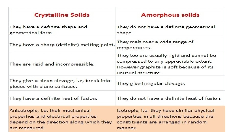
Amorphous Solids • The term amorphous solid is derived form a Greek word amorphous meaning no form. • The constituent particles are arranged in a short range order with a regular and periodically repeating pattern over short distances. • These solids get softened at a certain temperature and hence can be moulded and drawn into various desired shapes. Solids may also acquire crystalline form at some temperature when heated. • These solids have the ability to flow very slowly due to which they are also termed as pseudo solids or super cooled liquids. • These solids are isotropic in nature due to the absence of long range order and irregular arrangement of the constituent particles in all direction. This leads to same value of physical property along all the direction. • Glass, rubber, amorphous silicon and plastics are typical examples of amorphous solids. • Amorphous silicon is a photovoltaic material widely used for conversion of sunlight into electricity.
Crystalline Solids • This range of solids consists of a broad range of small crystals having a definite characteristic geometrical shape. • Fig. Crystals are crystalline solids • The constituent particles are arranged in a long range order (symmetry and regularity of arrangement of constituent particles that repeat at any distance from a given atom due to the interaction between the particles) with a regular and periodically repeating pattern over the entire crystal.
• Crystalline solids possess a sharp melting point. • Crystalline solids are anisotropic in nature due to different arrangement of particles in different directions. This leads to different value of physical property along different directions in the same crystals. • Metallic elements including iron, copper and silver are typical examples of crystalline solids. • On the other hand non – metallic elements like sulphur, phosphorus and iodine and compounds like sodium chloride, zinc sulphide and naphthalene and quartz are typical examples of crystalline solids.
CRYSTALLINE SOLID MOLECULAR SOLIDS IONIC SOLIDS METALLIC SOLIDS COVALENT SOLIDS
MOLECULAR SOLIDS Solid composed of molecules as constituent particles. These solids can further be categorized into following types: NON-POLAR MOLECULAR SOLIDS • They are composed of either atom. • H 2, Cl 2 and I 2. are some of the typical example. • In NON-POLAR MOLECULAR SOLIDS the comprised atoms or molecules are held together by weak dispersion forces or London forces. • They are soft and non-conductors of electricity. • They have low melting points and usually exist in liquid or gaseous state at room temperature and pressure.
POLAR MOLECULAR SOLIDS • The molecules like HCl, SO 2, are formed by polar covalent bonds. • In polar Molecular solids the comprised atoms or molecules are held together by stronger dipole-dipole interactions. • They are soft and non-conductors of electricity. • The melting points of these solids are higher than those of non-polar molecular solids and usually exist in liquid or gaseous state at room temperature and pressure. • Molecules like SO 2 and solid NH 3 are some examples of such solids.
HYDROGEN BONDED MOLECULAR SOLIDS • Hydrogen Bonded Molecular Solids contain polar covalent bonds between H and F, O or N atoms. • Strong hydrogen bonding binds molecules of such solids like H 2 O (ice). • They are non-conductors of electricity and are volatile liquids or soft solids under room temperature and pressure.
IONIC SOLIDS • The constituent particles of these solids are ions. • The solid is composed of three dimensional arrangements of cations and anions that are bonded by strong coulombic (electrostatic) forces. • These solids are hard and brittle in nature and have high melting and boiling points. • They are electrical insulators in solid state due to the absence of movement of free electrons but are good conductors in molten state due to the movement of ions.
METALLIC SOLIDS • Each metal atom donates one or more electrons to the group of mobile electrons which increases the electrical and thermal conductivity of the metallic elements. • Application of electric field makes these electrons flow through the linkage of positive ions. • Whereas application of heat to one portion of a metal makes thermal energy spread uniformly throughout by free electrons. • Presence of free electrons in metals makes them lustrous, malleable and ductile. For example, Cr, Fe etc.
COVALENT SOLIDS • Crystalline solids of non-metals comprises of covalent bonds between adjacent atoms that are strong and directional in nature due to which atoms are held very strongly at their positions all over the crystal. • They are also called giant molecules. • These solids are very hard and brittle. • They have extremely high melting points and may decompose before melting. • They are insulators and do not conduct electricity. • Diamond and silicon carbide are typical examples of such solids but Graphite is an exception as it is soft and a good conductor of electricity.
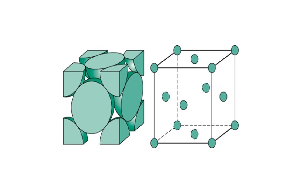
CRYSTAL LATTICE AND UNIT CELLS • Crystalline solids have a regular and periodically repeating pattern of constituent particles. • The diagrammatical representation of three dimensional arrangements of constituent particles of a crystal in space with each particle depicted as a point is called crystal lattice. • There are only 14 possible three dimensional lattices and are known Bravais Lattices. • Each point in a lattice is called lattice point or lattice site. • Each point in a crystal lattice signifies one constituent particle which can be an atom, a molecule or an ion. • Lattice points are joined together using straight lines to identify the geometry of the lattice.
UNIT CELL • Unit cell can be described as the smallest portion of a crystal lattice which when repeated in different directions, generates the entire lattice. • A unit cell is characterized by: • (i) Its dimensions along the three edges, a, b and c which may or may not be mutually perpendicular. • Angles between the edges, α (between b and c) β (between and c) and γ (between a and b). Thus, a unit cell is characterized by six parameters a, b, c, α, β and γ.
PRIMITIVE UNIT CELL • If the constituent particles of a crystal lattice are present only on the corner positions of a unit cell, it is known as primitive unit cell.
BODY-CENTRED UNIT CELL Such a unit cell contains one constituent particle (atom, molecule or ion) at its bodycentre besides the ones that are at its corners.
FACE CENTRED UNIT CELL • If the constituent particles of a unit cell are present at the center of each face, besides the ones that are at its corners, then it is a face centred unit cell, fcc
END-CENTRED UNIT CELL • If the constituent particles of a unit cell are present the center of any two opposite faces besides the ones present at its corners, then it end-centred unit cell.
No. of atoms in a unit cell • Number of atoms per unit cell : Primitive Cubic Unit Cell • Each cubic unit cell has 8 atoms on its corners. • Therefore total number of atoms in one unit cell = 8 * 1/8 = 1 atom •
Number of atoms per unit cell : Body Centered Cubic Unit Cell • In a body-centered cubic (bcc) unit cell, the atoms are present in the body-center besides the ones that are at its corners that wholly belongs to the unit cell in which it is present. Thus in a body-centered cubic (bcc) unit cell: • 8 corners X 1/8 per corner atom = 8 * 1/8 • 1 body center atom = 1 X 1 • Total number of atoms per unit cell = 1 atom = 2 atoms
No. of atoms in FCC • Thus, in a face-centered cubic (fcc) unit cell: • 8 corners X 1/8 per corner atom = = 1 atom 8 * 1/8 • 6 face-centered atoms X 1/2 per unit cell = 6 X 1/2 = 3 atoms • Total number of atoms per unit cell = 4 atoms • In solids, these constituent particles are closelypacked that leaves minimum vacant space.
Close Packing in One Dimension • The only way to arrange spheres in a one dimensional close packed structure is to arrange the spheres in a single row and touching each other. • Each sphere is in contact with two of its surrounding atom. • The number of nearest surrounding particles is called its coordination number. Therefore in one dimensional close packed arrangement, the coordination number is 2.
CLOSE PACKING IN TWO DIMENSION
Close Packing in Three Dimensions • All real structures are three dimensional structures that are obtained by stacking two dimensional layers one above the other in a square closepacked and hexagonal closepacked manner. It can be categorized into two types: •
• Three dimensional close packing from two dimensional square close-packed layers: • The second layer is placed over the first layer in such a way that the spheres of the upper layer are exactly above those of the first layer. • In this arrangement of spheres, both the layers are perfectly aligned horizontally as well as vertically. • Let the first row be ‘A’ type row, and the second row be ‘B’ type row. • Thus this lattice has AAA. . type pattern. • The lattice therefore generated is the simple cubic lattice, and its unit cell is the primitive cubic unit cell.
• Three dimensional close packing from two dimensional hexagonal close packed layers: • Three dimensional close packed structure can be generated by placing layers one over the other. • Placing second layer over the first layer
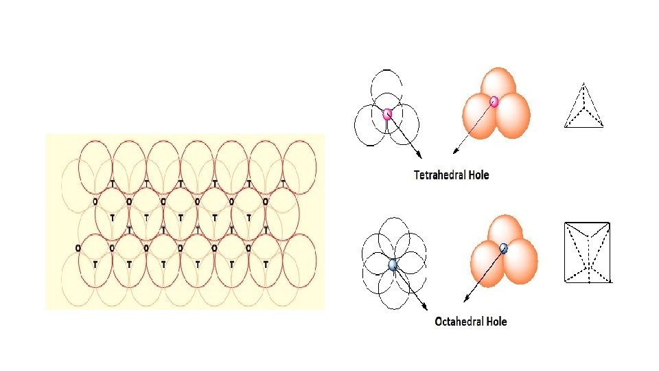
Placing second layer over the first layer • Consider a two dimensional hexagonal close packed layer of type ‘A’ and place a similar layer above it in such a way that the spheres of the second layer lies in the depressions of the first layer. • Let the second layer be of type ‘B’ due to its different alignment. • All the triangular voids of the first layer are not covered by the spheres of the second layer which gives rise to a different arrangement. • The area where a sphere of the second layer is above the void of the first layer (or vice versa) a tetrahedral void is formed. • These voids are called tetrahedral voids because a joining of the centers of four spheres gives rise to tetrahedron. • There areas where the triangular voids in the second layer lies above the triangular voids of the first layer, and the triangular shapes of these do not overlap. • One of them has the apex of the triangle pointing upwards and the other downwards.
• Such voids are surrounded by six spheres and are called octahedral voids (O). • Let the number of close packed spheres be N, then: • The number of octahedral voids generated in the structure = N. • The number of tetrahedral voids generated in the structure = 2 N.
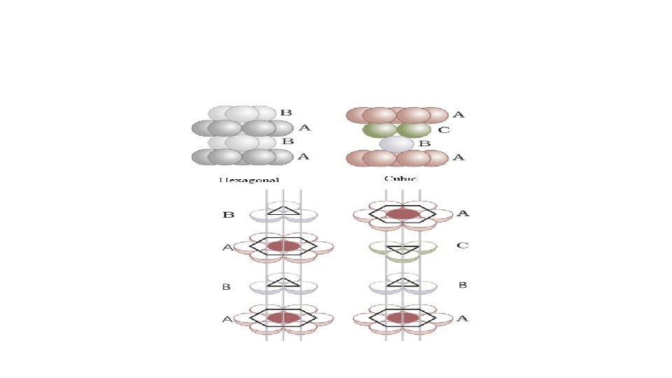
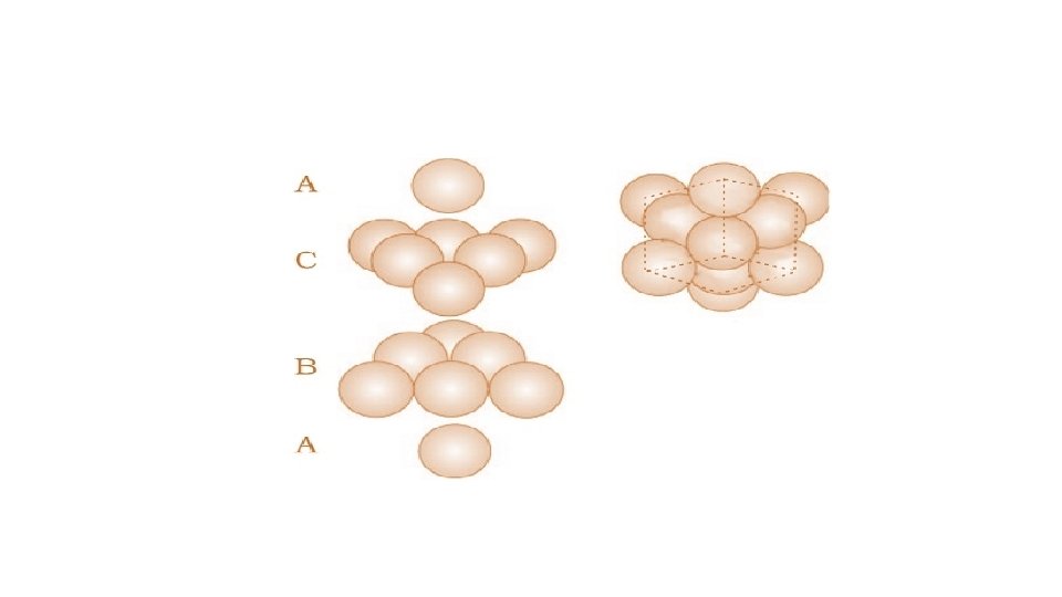
Placing third layer over the second layer : Covering Tetrahedral Voids • Tetrahedral voids of the second layer can get covered by the spheres of the third layer. • Here the spheres of the third layer get exactly aligned with the spheres of the first layer. • Therefore it can be observed that the pattern of spheres is repeated in alternate layers. • This pattern is often written as ABAB. . . . pattern and the structure is called hexagonal close packed (hcp) structure found in many metals like magnesium and zinc.
Placing third layer over the second layer : Covering Octahedral Voids • The third layer may be placed above the second layer in a manner such that its spheres cover the octahedral voids. • When placed in this manner, the spheres of the third layer are not aligned with • those of either the first or the second layer. This arrangement is called “C’ • Only when fourth layer is placed, its spheres are aligned with those of the first layer. • This pattern of layers is often written as ABCABC. . . This structure is called cubic close packed (ccp) or face-centered cubic (fcc) structure.
PACKING EFFICIENCY IN HCP & CCP • let the unit cell edge length be ‘a’ and face diagonal AC = b.
Each unit cell in ccp structure has effectively 4 spheres. Hence total volume of four spheres is equal to 4 X (4/3)Π r 3 and volume of the cube is a 3 or (2√ 2 r)3. Therefore, Packing efficiency = (Volume occupied by four spheres in the unit cell X 100)/( Total volume of the unit cell)
Efficiency of Packing in Body Centered Cubic Structures The length of the body diagonal c = 4 r, where r is the radius of the sphere as all the spheres along the diagonal touch each other. Therefore,
Packing efficiency = (Volume occupied by two spheres in the unit cell X 100)/( Total volume of the unit cell)
Packing Efficiency in Simple Cubic Lattice a = 2 r Where a = Edge length or side of the cube r = radius of each particle, The volume of the cubic unit cell = a 3 = (2 r)3 = 8 r 3 A simple cubic unit cell contains only 1 atom. The volume of the occupied space =4/3 Π r 3 Packing efficiency = (Volume of one atom X 100)/( Volume of cubic unit cell)
• Edge length of a unit cell of a cubic crystal = a, • Density of the solid substance = d • Molar mass = M • Volume of a unit cell = a 3 • Mass of the unit cell = number of atoms in unit cell × mass of each atom = number of atoms present in one unit cell (z) × mass of a single atom (m)
Imperfections in Solids Constituent particles in crystalline solids are arranged in a short range as well as long range order yet crystals are not perfect. They possess small crystals have defects that are irregularities in the arrangement of constituent particles in them when crystallization process occurs at fast or moderate. These defects are of two types- point defects and line defects. The irregularities or deviations from ideal arrangement around a point or an atom in a crystalline substance. The irregularities or deviations from ideal arrangement in entire rows of lattice points are known as line defects. • These irregularities are called crystal defects. • Point defects can be classified into three types: (i) stoichiometric defects • (ii) impurity defects and (iii) non-stoichiometric defects • •
Stoichiometric Defects • These ranges of point defects do not disturb the stoichiometry of • the solid. • They are also called intrinsic or thermodynamic defects. • Non-ionic solids exhibit their defects as vacancy defects and interstitial defects. Vacancy Defect: A crystal containing vacant lattice sites is said to have vacancy defect. This defect can also develop due to heating up of a substance.
Interstitial Defect: A crystal in which some constituent particles occupy an interstitial site, are said to have interstitial defect which increases the density of the substance. Frenkel Defect: This defect is exhibited by the ionic substances due to the large difference in size of ions. The smaller ion (cation) is displaced from its normal site to an interstitial site which creates a vacancy defect at its original site and an interstitial defect at the new location. It is also called dislocation defect. It does not alter the density of the solid. For example, Zn. S, Ag. Cl, Ag. Br and Ag. I due to small size of Zn 2+ and Ag+ ions.
SCHOTTKY DEFECT • This defect in ionic solids is equivalent to the vacancy defect in non-ionic solids. • In order to maintain electrical neutrality, the number of missing cations and anions are equal • Schottky defect also decreases the density of the substance. • This defect is shown by ionic substances in which the cation and anion are of almost similar sizes. • For example, Na. Cl, KCl, Cs. Cl and Ag. Br. • Out of these Ag. Br shows both, Frenkel as well as Schottky defects.
Impurity defect • Crystallization of molten Na. Cl with little amount of Sr. Cl 2 results in Sr 2+ occupying some of the sites of Na+ • Each Sr 2+ replaces two Na+ ions. • It occupies the site of one ion and the other site remains vacant. • The cationic vacancies thereby produced are equal in number to that of Sr 2+ • Solid solution of Cd. Cl 2 and Ag. Cl
Non-Stoichiometric Defects • Nonstoichiometric inorganic solids contain the constituent elements in a non-stoichiometric ratio due to defects in their crystal structures. • These defects are of two types: (i) metal excess defect and • (ii) metal deficiency defect. (i) Metal Excess Defect. Metal excess defect due to anionic vacancies: This type of defect is exhibited by alkali halides like Na. Cl and KCl. Application of heat to Na. Cl in an atmosphere of sodium vapour results in deposition of the sodium atoms on the surface of the crystal. The sodium atoms lose electron to form Na+ The Cl– ions diffuse to the surface of the crystal and combine with Na atoms to give Na. Cl.
• The released electrons diffuse into the crystal and occupy anionic sites. • The anionic sites occupied by unpaired electrons are called Fcentres that imparts yellow colour to the crystals of Na. Cl due to the excitation of the electrons on absorption of energy from the visible light falling on the crystals. • Excess of lithium makes Li. Cl crystals pink and excess of potassium makes KCl crystals violet. Metal excess defect due to the presence of extra cations at interstitial sites: Heating Zinc oxide that exists in white colour at room temperature loses oxygen and turns yellow. This results in excess of zinc in the crystal and its formula becomes Zn 1+x O. The excess Zn 2+ ions move to interstitial sites and the electrons to neighbouring interstitial sites.
Metal Deficiency Defect: • Many solids possess less amount of the metal as compared to the stoichiometric proportion. • For example, Fe. O is mostly found with a composition ranging from Fe 0. 93 O to Fe 0. 96 O. • In crystals of Fe. O some Fe 2+ cations are missing and the loss of positive charge is made up by the presence of required number of Fe 3+ •
Conduction of Electricity in Semiconductors In semiconductors, the gap between the valence band conduction band is small. • This enables some electrons to jump to conduction band exhibit their conductivity. • Electrical conductivity of semiconductors increases with increase in temperature, since more electrons can jump to the conduction band due to small gap between the valence band conduction band. • Silicon and germanium exhibit this behavior and are called intrinsic semiconductors. • The conductivity of these intrinsic semiconductors is too low to be practically used.
Doping The conductivity of metal is increased by adding an appropriate amount of suitable impurity. This process is known as doping. It can be performed with an impurity which is electron rich or electron deficient than the intrinsic semiconductor silicon or germanium.
Electron – rich impurities • In a periodic table Silicon and germanium belongs to group 14 with four valence electrons each. In their crystals each atom forms four covalent bonds with surrounding atom. • When doped with a group 15 element like P or As, which contains five valence electrons, • Four out of five electrons are used in the formation of four covalent bonds with the four neighbouring silicon atoms. The fifth electron in P is extra and becomes delocalized. • These delocalized electrons increase the conductivity of doped silicon (or germanium). • This type of semiconductor is known as n-type semiconductor because the increase in conductivity is due to the negatively charged electron.
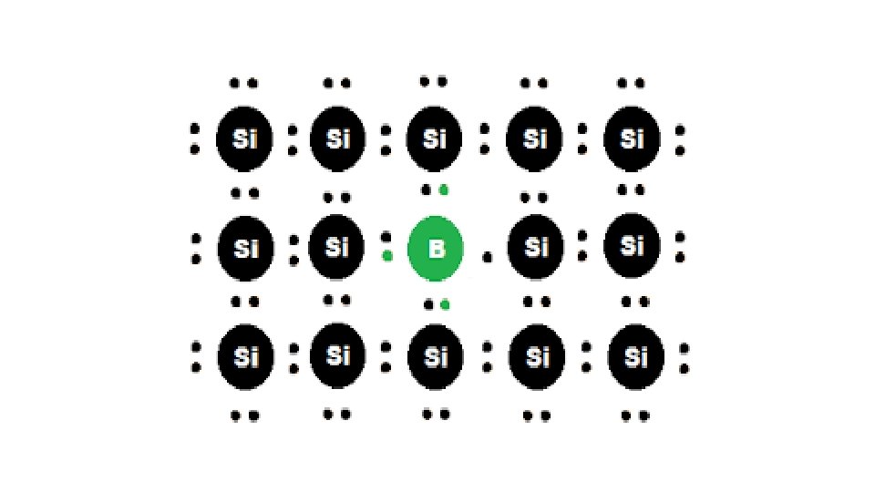
Electron – deficit impurities Silicon or germanium of group 14 can also be doped with elements of group 13 element like B, Al or Ga which contains only three valence electrons. Three electrons of B form covalent bonds with three electrons of Si. The fourth electron in Si is extra that remains isolated and creates an electron hole or electron vacancy.
• On the basis of their magnetic properties, substances can be classified into five categories: • Paramagnetic • Diamagnetic • Ferromagnetic • Antiferromagnetic • Ferrimagnetic.
• Paramagnetism • Paramagnetic substances are weakly attracted on application of magnetic field. • It is due to presence of one or more unpaired electrons that gets attracted by the magnetic field. • Application of a magnetic field magnetizes the paramagnetic substances in the same direction. • They lose their magnetism in the absence of magnetic field. • O 2, Cu 2+, Fe 3+, Cr 3+ are some examples of such substances.
• Diamagnetism • Diamagnetic substances are weakly repelled by a magnetic field. • This property is represented by the substances in which all the electrons are paired and there are no unpaired electrons. • They are weakly magnetized on application of magnetic field in opposite direction. • Pairing of electrons cancel out their magnetic moments and they lose their magnetic character. • For example, H 2 O, Na. Cl and C 6 H 6 are some examples of such substances.
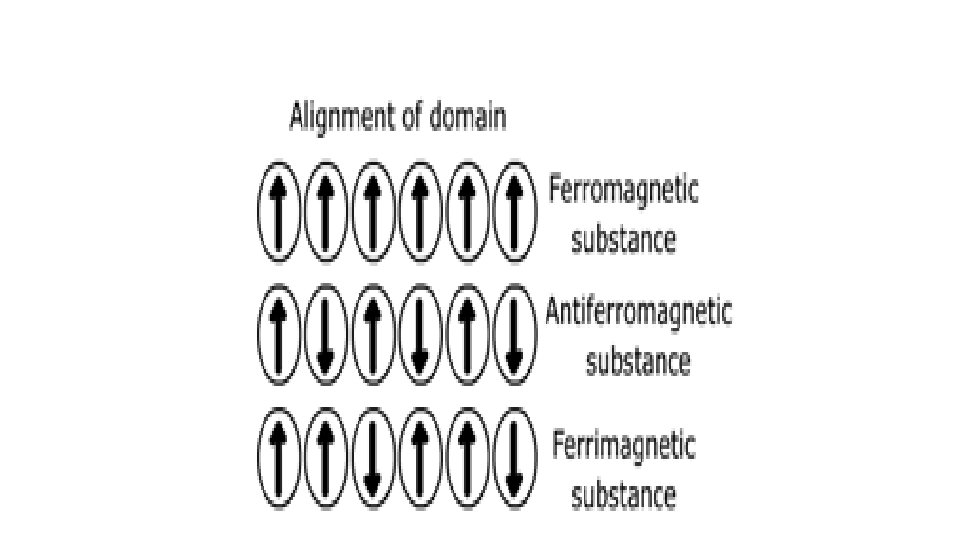
• Ferromagnetism • Ferromagnetic substances get strongly attracted towards magnetic field. • They can be permanently magnetized. • In solid state, the metal ions of ferromagnetic substances are grouped together into small regions and are known as domains that act as a tiny magnet. • In an unmagnetised ferromagnetic substance the domains are randomly oriented that cancels out their magnetic moments. • When placed in a magnetic field all the domains of the substance get oriented in the direction of the magnetic field producing a strong magnetic effect which persists even on removal of the magnetic field and the ferromagnetic substance becomes a permanent magnet. • For example, iron, cobalt, nickel, gadolinium and Cr. O 2 are ferromagnetic substances.
ANTIFERROMAGNETISM • Substances like Mn. O showing antiferromagnetism have domain structure similar to ferromagnetic substance, but the domains are oppositely oriented and cancel out ecah other's magnetic moment. FERROMAGNETISM • Magnetic moments of the domains in the substance are aligned in parallel and antiparallel directions in unequal numbers they are weakly attracted by manetic field as compared to ferromagnetic substances. Fe 3 O 4, Mg. Fe 2 O 4, Zn. Fe 2 O 4. • These substances loose ferrimagnetism on heating and become paramagnetic.
• https: //youtu. be/B 1 Jz. FAD 1 GAo • https: //youtu. be/li. ECfpbe. Ixw https: //youtu. be/L 2 jva 8 j n. GAM