Chapter Seven Underground Cables 1 Introduction Underground cables

Chapter Seven Underground Cables 1

Introduction �Underground cables have several advantages such as less liable to damage through storms or lightning, less chances of faults, smaller voltage drop and better general appearance. �However, their major drawback is that they have greater installation cost and introduce insulation problems at high voltages compared with the equivalent overhead system. �For this reason, underground cables are employed where it is impracticable to use overhead lines. 2

�An underground cable essentially consists of one or more conductors covered with suitable insulation and surrounded by a protecting cover. �Several types of cables are available and the type of cable to be used will depend upon the working voltage and service requirements. �They may be classified in two ways according to the type of insulating material used in their manufacturing or/and the voltage for which they are manufactured. 3

�In general, an underground cable must fulfil the following necessary requirements : 1. The conductor used should be tinned stranded copper or aluminium of high conductivity. Stranding is done so that conductor may become flexible and carry more current. 2. The conductor size should be such that the cable carries the desired load current without overheating and causes voltage drop within permissible limits. 4

3. The cable must have proper thickness of insulation in order to give high degree of safety and reliability at the voltage for which it is designed. 4. The cable must be provided with suitable mechanical protection so that it may withstand the rough use in laying it. 5. The materials used in the manufacture of cables should be such that there is complete chemical and physical stability throughout. 5

Insulating Materials for Cables �In general, the insulating materials used in cables should have the following properties : 1. High insulation resistance to avoid leakage current. 2. High dielectric strength to avoid electrical breakdown of the cable. 3. High mechanical strength to withstand the mechanical load on the cables. 4. Low cost so as to make the underground system a viable proposition. 6

5. Non-inflammable. 6. Non-hygroscopic i. e. , it should not absorb moisture from air or soil. The moisture tends to decrease the insulation resistance and hastens the breakdown of the cable. In case the insulating material is hygroscopic, it must be enclosed in a waterproof covering like lead sheath. 7. Unaffected by acids and alkalies to avoid any chemical action. 7

�The principal insulating materials used in cables are: v. Rubber v. Vulcanised India Rubber (VIR) v. Impregnated Paper v. Varnished Cambric v. Polyvinyl Chloride (PVC) 8

Electric Stress in a Single-Core Cable �If the dielectric strength of the insulating material is exceeded during the operation of the cable, the insulation will break down. �Hence, the cable must be designed so that the electric field strength, or the maximum electric stress, at the surface of the conductor does not exceed that required to break down the insulation. �It has been found that the optimal ratio of the radius of the cable to the radius of the conductor is given by: 9

�Smaller ratios will result in unstable cable operation, in that the dielectric will tend to break down. �Any ratio exceeding 2. 718 will result in satisfactory cable operation. �For economic reasons, however, it is best to maintain the ratio close to 2. 718. 10

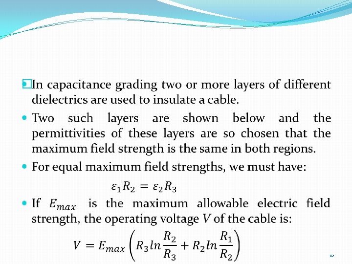
Grading of Cables �In order to minimize the difference between the maximum and minimum electric field strengths in the cable, many cables contain several layers of dielectric material. �This process is known as grading, and two types of grading are commonly used. (Capacitance grading and inter-sheath grading) 11

13

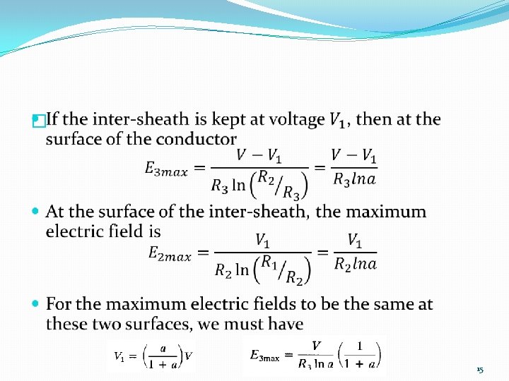
�In inter-sheath grading, the cable contains several layers of a single dielectric material, separated by coaxial metallic sheaths that are inserted into the dielectric and maintained at predetermined voltages. �A cable with one such inter-sheath is shown below. 14

Cable Capacitance �The capacitance per unit length of a single-conductor cable is given by: �In a three-conductor cable, the capacitances between pairs of conductors and between the conductors and the sheath are shown below, where equilateral spacing is assumed. �To find the capacitance per phase, the delta connected capacitances are changed to their equivalent wye form. 16

17

Cable Inductance �The inductance per unit length of a single conductor cable is given by: �Analytical expressions leading to the per phase inductance of a three conductor cable are extremely cumbersome and are beyond the scope of this course. 18

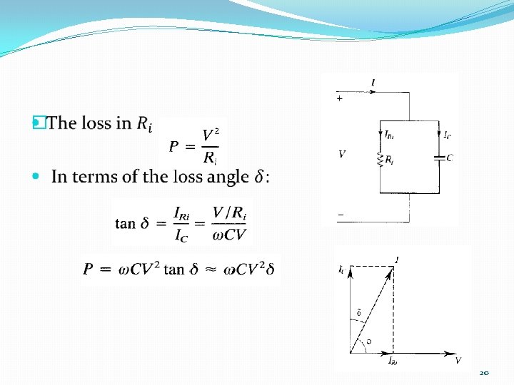
Dielectric Loss and Heating � 19

Overhead Lines versus Underground Cables �The inductance is more predominant in case of overhead lines whereas capacitance in the case of underground cables. �The large charging current on very high voltage cables limits the use of cables for long length transmission. �The conductor in the overhead line is less expensive than the underground cable. The size of the conductor for the same power transmission is smaller in case of overhead lines than the cables because of the better heat dissipation in overhead line. 21

�The insulation cost is more in case of cables than overhead lines. �The erection cost of an overhead line is much less than the underground cable. 22
- Slides: 22