CHAPTER NO 4 NETWORK REFERENCE MODEL What is


 MODEL The")


 � Gives data to the NIC � Controls access")
 �")


 originally developed Transmission")


 � Allows end-to-end communication � Connection establishment, error")


- Slides: 31
CHAPTER NO. 4 NETWORK REFERENCE MODEL What is Network Reference Model? A network reference model defines the functions of communication software in a generalized and structured manner which helps to carry out the network product development activities.
- To reduce the design complexity networks are organised as a series of layers or levels , one above the other as shown in the figure. - The number of layers , the name of each layer, the content of each layer and the function of each layer differ from network to network. Layer n protocol Layer 2 protocol Layer 1 protocol
REFERENCE MODEL OSI REFERENCE MODEL TCP/IP REFERENCE MODEL OPEN SYSTEM INTERCONNECTION (OSI) MODEL The OSI model is a layered framework for design of network system that allows communication between all types of network systems.
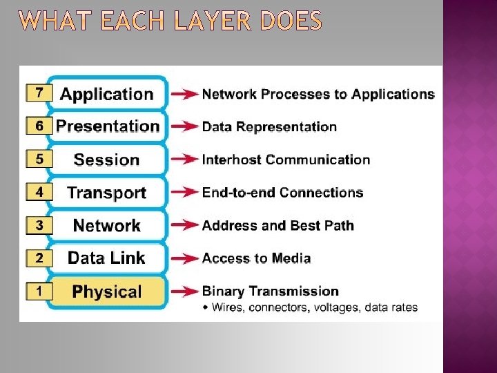
- OSI model consist of seven separate but related layers, each of which defines a part of process of moving information about network. - An understanding of the fundamentals of the OSI model provides a solid basis for exploring data communications. 7 Application 6 Presentation 5 Session 4 Transport 3 Network 2 Data link 1 Physical Fig. Seven layers of the OSI model
WHO DEVELOPED THE OSI MODEL? - The OSI model was developed in two different projects by the International Organisation for Standardization (ISO) and Consultative Committee for International Telephone and telegraphy(CCITT) which is now known as ITU-T. - Both these organization developed their own seven layer models. Then in 1983 the two projects were combined together. INTERLAYER COMMUNICATION - Just as we package a letter by placing it in an envelope and write an address on it, the networking protocols also package the data generated by an application, puts an address on it and sends to the destination computer. - In order an idea get idea of interlayer communication, let us take a simple example first. Consider a three layer model of following figure.
Machine 1 Machine 2 Layer 3 Layer 2 Layer 1 Physical medium Data and control information We want the data to get transferred from layer-3 of machine-1 to layer 3 of machine-2. But the data does not get transferred directly from layer 3 of one machine to layer 3 of the other machine. Instead the data transfer takes place as explained below The data and control information is passed on to the lower layers until the lowest layer (layer 1) is reached. Below layer 1 lies the physical medium such as coaxial cable, through which actual communication takes place.
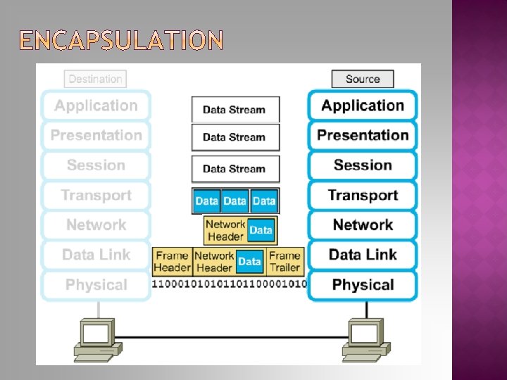
ENCAPSULATION Encapsulation is the technique used by layered protocols in which a layer accepts a message from a layer above it and places it in the data portion of the lower level layers message unit. As data moves down the layers, additional information will be appended to it, and it may be segmented into smaller pieces. E-MAIL
Figure 2. 3 An exchange using the OSI model
� Determines the specs for all physical components � Cabling � Interconnect methods (topology / devices) � Data encoding (bits to waves) � Electrical properties � Examples: � Ethernet (IEEE 802. 3) � Token Ring (IEEE 802. 5) � Wireless (IEEE 802. 11 b)
Physical layer The physical layer is responsible for the movement of individual bits from one hop (node) to the next.
� Places data and retrieves it from the physical layer and provides error detection capabilities 3
Data link layer The data link layer is responsible for moving frames from one hop (node) to the next.
� MAC (Media Access Control) � Gives data to the NIC � Controls access to the media through: CSMA/CD Carrier Sense Multiple Access/Collision Detection Token passing � LLC (Logical Link Layer) � Manages the data link interface (or Service Access Points (SAPs)) � Can detect some transmission errors using a Cyclic Redundancy Check (CRC). If the packet is bad the LLC will request the sender to resend that particular packet.
� Provides network-wide addressing and a mechanism to move packets between networks (routing) � Responsibilities: � Network addressing � Routing � Example: � IP from TCP/IP 3
Network layer The network layer is responsible for the delivery of individual packets from the source host to the destination host.
� Provides reliable data delivery � It’s the TCP in TCP/IP � Receives info from upper layers and segments it into packets � Can provide error detection and correction 3
Transport layer The transport layer is responsible for the delivery of a message from one process to another.
� Allows applications to maintain an ongoing session � Where is it on my computer? �Workstation and Server Service (MS) �Windows Client for Net. Ware (Net. Ware) 3
� Gives end-user applications access to network resources � Where is it on my computer? � Workstation or Server Service in MS Windows 3
7 - Application All 6 - Presentation People 5 - Session Seem 4 - Transport To 3 - Network Need 2 - Data Link Data 1 - Physical Processing
� The late-60 s The Defense Advance Research Projects Agency (DARPA) originally developed Transmission Control Protocol/Internet Protocol (TCP/IP) to interconnect various defense department computer networks. � The Internet, an International Wide Area Network, uses TCP/IP to connect networks across the world.
� Layer 4: � Layer 3: � Layer 2: � Layer 1: Application Transport Internet Network access It is important to note that some of the layers in the TCP/IP model have the same name as layers in the OSI model. Do not confuse the layers of the two models.
� Concerned with all of the issues that an IP packet requires to actually make the physical link. All the details in the OSI physical and data link layers. �Electrical, mechanical, procedural and functional specifications. �Data rate, Distances, Physical connector. �Frames, physical addressing. �Synchronization, flow control, error control.
� Send source packets from any network on the internetwork and have them arrive at the destination independent of the path and networks they took to get there. �Packets, Logical addressing. �Internet Protocol (IP). �Route , routing table, routing protocol.
� The transport layer deals with the quality-ofservice issues of reliability, flow control, and error correction. �Segments, data stream, datagram. �Connection oriented and connectionless. �Transmission control protocol (TCP). �User datagram protocol (UDP). �End-to-end flow control. �Error detection and recovery.
� 3. Transport layer (layer 3) � Allows end-to-end communication � Connection establishment, error control, flow control � Two main protocols at this level Transmission control protocol (TCP), � Connection oriented Connection established before sending data Reliable user datagram protocol (UDP) � Connectionless Sending data without establishing connection Fast but unreliable
� Handles high-level protocols, issues of representation, encoding, and dialog control. � The TCP/IP combines all application-related issues into one layer, and assures this data is properly packaged for the next layer. �FTP, HTTP, SMNP, DNS. . . �Format of data, data structure, encode … �Dialog control, session management …
OSI Model TCP/IP Hierarchy Protocols 7 th Application Layer 6 th Presentation Layer Application Layer 5 th Session Layer 4 th Transport Layer 3 rd Network Layer 2 nd Link Layer 1 st Physical Layer Link Layer Network Layer Transport Layer Application Layer Link Layer : includes device driver and network interface card : handles the movement of packets, i. e. Routing : provides a reliable flow of data between two hosts : handles the details of the particular application