CHAPTER FOUR NETWORK DESIGN AND ANALYSIS OVERVIEW Introduction


 3 3")
 4")

 are mechanical")


 Pump")

 • • Fixed volume")
 Pump 14")
 pump")


 Hp 2 Pumps 1 Pump Q 23")


")

")
")


specific speed • • • refers the speed of geometrically similar turbine")


 SP…. . Suction Pipe PR…. . Delivery pipe")


 • • The curve of the amount of")

 • • q Some times called head capacity curve It’s the")


- Slides: 54
CHAPTER FOUR NETWORK DESIGN AND ANALYSIS OVERVIEW Introduction to hydraulic machine q. Pumps q. Turbines qnetwork - pump-pipe network q 1
What is the practical importance of this chapter? Hydropower system q Turbine-generator network q Turbine-penstock network q Design of Pump stations q q To deliver water from the source for different purposes 2
Practical application…hydropower plant(turbines) 3 3
Practical application…pumping water(pump) 4
objective • • • To understand the general characteristics of hydraulic machines To differentiate the difference b/n turbine and pump To understand the relationship between head and flow in a pump to determine the power requirements of pumps Apply continuity and energy equations to pipe systems involving pump 5 Matching pumps to pipelines
4. 1 Introduction to hydraulic machine q • Hydraulic machines (Fluid machines) are mechanical devices that either extract energy from a fluid(e. g. turbines) or add energy to a fluid(e. g. pump) Generally classified into two categories Positive displacement machine(static type) q Turbo machine(dynamic type) q 6
4. 1. 1 Positive displacement machine Ø Ø These machines force a fluid into or out of a chamber by changing the volume of the chamber. The pressure developed and the work done are a result of essentially static forces rather than dynamic forces. Ø Example: tire pump , heart 7
4. 1. 2 Turbo machine Ø Ø These machines involve a collection of blades, buckets , flow channels or passages arranged around an axis of rotation to form a rotor. Rotation of the rotor produces dynamic effects that either add energy to the fluid or remove energy from the fluid. Ø Example: water pump , water turbines 8
Pumps 9
4. 2 Pumps • Def’n: device that uses external power source to apply force to a fluid in order to move it from one place to another § • 1) When the fluid is to be pumped over long distance. 2) When the fluid is to be pumped to higher elevation. Must overcome: • • • Practical application: - (1) frictional forces from large quantities of fluid (2) difference in static pressure between two locations 10 Must provide any desired velocity
4. 2. 1 Components of Pumps • • Drive mechanism (steam, electric, gear) Pump shaft----C Impeller or piston Casing----F 11
Components of pump 12
4. 2. 2 Types of Pumps • Positive Displacement (reciprocating) • • Fixed volume of fluid is displaced during each cycle regardless of static head/pressure pumping against Uses either a piston, gear, or screw type (reciprocating, rotary gear, rotary screw, etc) Components : look at the figure below Reciprocating pump is now-a days outdating 13
Positive Displacement(reciprocating) Pump 14
Positive displacement (reciprocating) pump
cont… • Non-positive Displacement: volume of fluid is dependent on static head/pressure • Centrifugal: impeller inside a casing (called volute). Impeller is a disc with curved vanes mounted radially (like a pedal wheel) • • Suction is the Eye through which fluid accelerated as it travels outward & then enters volute Of two types: volute pump, diffuser pump(turbine pump) Components: look at the picture below 16 As compared to reciprocating pumps centrifugal
Centrifugal Pump 17
Centrifugal Pump
Centrifugal Pump 19
Pump Characteristic Curves • Pump Parameters: • • • N = pump speed, rpm Q= volumetric flow rate, m 3 /s Hp = pump head (discharge pressure), m P = power required, watt Centrifugal Pump Laws • • • Va. N Hp a N 2 W a N 3 20
Positive Displacement Pumps N 1 N 2 Hp Q 21
Centrifugal Pumps • Parallel Pumps Hp 2 Pumps 1 Pump Q 22
Centrifugal Pumps • Series pumps (called staging) Hp 2 Pumps 1 Pump Q 23
Turbines 24
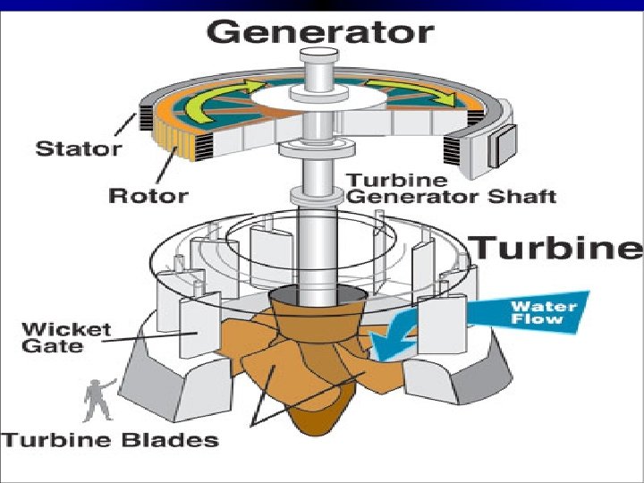
How Hydropower Works ? # Hydropower plants capture the energy of falling water to generate electricity. # A turbine converts the kinetic energy of falling water into mechanical energy Outflow during a test at the hydropower plant at the Hoover Dam, located on the Nevada-Arizona
Turbines Ø The literature on power generation gives the following definitions of turbines Ø A machine wherein rotary motion is obtained by centrifugal force which results from a change in the direction of high velocity fluid jet.
Turbines • • • A hydraulic turbine uses the potential and kinetic energy of water and converts in to usable mechanical energy. A fluid energy is available in the natural or artificial high level water reservoirs which are created by constructing dams at appropriate places in the flow path of the rivers. When water from the reservoirs is taken in to turbines, transfers of energy takes place in the blade passage of the unit.
Turbines • • • Their application lies in the filed of electric power generation. The mechanical energy made available at the turbine shaft is used to run an electric generator which directly coupled to the turbine shaft. The power is generated by utilizing potential energy.
Type of Turbines • Based on basic operating principles, hydraulic turbines are categorized in to impulse and reaction turbines depending on whether the pressure head available is fully or partially converted into kinetic energy in the nozzle.
Impulse turbine v Impulse turbines, available hydraulic energy is first converted in to kinetic energy by means of an efficient nozzle. ü The high velocity head(jet) issuing from the nozzle then strikes a series of suitable shaped buckets fixed around the wheel ü ü ü The buckets change the direction of jet with out changing its pressure. An impulse turbine operates under atmospheric pressure. Important impulse turbines are Pelton wheel, tugoimpulse wheel, girede turbine. Pelton wheel is predominantly used
Impulse turbine (Pelton)
Reaction Turbines • • • When the part of the total available hydraulic energy is transformed in to kinetic energy before the water is taken in to runner. A substantial part remains in the form of pressure energy. The flow from inlet to outlet of the turbine is under pressure and blades of a reaction turbines are closed passages sealed from atmospheric conditions. Important reaction turbine are; Francis, Kaplan, Thomson and propeller turbines. Francis and Kaplan turbines are widely used at present.
Reaction turbine (Kaplan)
Reaction turbine (Francis)
Impulse versus Reaction turbines • Impulse turbines • • • All available energy of the fluid is converted in to kinetic energy by an efficient nozzle that forms a free jet. The jet is unconfined and exposed to atmospheric pressure. Flow regulation is possible without loss • Reaction turbines • • Only the portion of the fluid energy is transferred into kinetic energy before the fluid enters to the turbine. Water enter with an excess pressure and velocity.
Cont… • • The wheel does not run full and air has free access to the buckets. Casing has no hydraulic function it only serves prevents splashing and to guide the water to tail race. • • Flow regulation is always accompanied by loss Water competing fills the vane passages through the operation of the turbine.
In addition to the concept of impulse and reaction, Hydraulic turbines may be future classified in to various • I) Direction of water flow through runner Turbines Tangential flow(Pelton wheel) Axial or parallel flow(Kaplan turbine) Outward radial flow Inward radial flow Mixed, radial and axial (Modern Francis turbines)
Cont… II )specific speed • • • refers the speed of geometrically similar turbine , which will develop unit power when working under unit head. The turbine specific speed is prescribed by the relation Ns=N√P/H 5/4 • Where p is power in KW • H is the net available head in m • N is the speed is rpm Specific speed is characteristic index which service to identify the type of hydraulic model.
Cont… • • For Pelton wheel , Ns=9 -17 for a slow runner =17 -25 for normal runner =25 -30 for fast runner = for double jet Francis turbine Ns= 50 -100 for slow runner =100 -150 for
Cont… III Available head • High head turbine operating under head above 250 m Pelton wheel is high head turbine and relatively require small rates of flow. • Medium head working under head 60 -250 m and require medium flow rate. E. g. Francis • Low head turbines which operate up to 30 m require very large volumetric rates of flow. E. g. axial flow turbines propeller or Kaplan.
Cont… IV Position of shaft Impulse , turbines have usually a horizontal shaft and vertical runner arrangement. Reaction, turbine may be either vertical or horizontal shape type. •
Pipe pump network design 43
Cont… q q q Over view Delivery and Suction pipe Static and total head System characteristic curve Pump capacity curve(head-discharge curve) Net Positive Suction Head(NPSH) q Cavitation 44
Delivery and Suction pipe Fig. a: suction and delivery pipe 45
cont… R…. reservoir, p… pump, S…sump(source) SP…. . Suction Pipe PR…. . Delivery pipe Ø The pipeline can be separated into the suction pipe and the delivery pipe. Ø Suction pipe: connects the source(sump)and the inlet of the pump. Ø Delivery pipe: connected at its lower end to the outlet of the pump and delivers the liquid to the required height. 46
Cont… • • Pump operation adds energy to water in the pipeline by boosting the pressure head. The suction side of the system from the supply reservoir to the inlet of the pump is subjected to negative pressure in energy equation.
Static and total head • Ø Ø From fig. a hs : suction head, hd : delivery head Static head(h)= hs + hd Total head(H)=h+hf+v 2/2 g , where: hf=all losses(including major and minor losses in suction and delivery pipe) v=velocity in the delivery pipe neglecting that of suction pipe 48 due to
System characteristic curve (system head curve) • • The curve of the amount of discharge(Q) required versus the total head(H) of the system. i. e. pipe network (in this case) Generally can be expressed by: H=h+k. Q 2, where h=static head H=total head Q=required discharge K=coefficient which accounts losses in the system 49
Cont… a 50
Pump capacity curve(centrifugal) • • q Some times called head capacity curve It’s the curve of the discharge capacity versus head capacity of the pump i. e. head-discharge(H-Q) curve (Look at fig. a) Point ‘a’ is called operating point 51
Net Positive Suction Head • • Def’n: the pressure required at the suction of a pump to prevent cavitation. So what is cavitation? • • the formation of bubbles due to low pressure area and the subsequent collapse upon migration to a high pressure area Cavitation causes noise and damage 52
Net Positive Suction Head • • • Need enough pressure on the suction side so that the pump does not reduce pressure @ the eye to cause P < Psat If P < Psat, water flashes to vapor causing damage to the pump What are possible means of preventing cavitation? q Priming: the operation in which the suction pipe , casing of the pump and the portion of the delivery pipe up to the delivery valve is completely filled with the liquid to be pumped before starting the pump so as to evacuate air. 53
Thank Questions? you! 54