CHAPTER 9 Moments of Inertia 9 1 INTRODUCTION


 Determine the centroidal polar moment of inertia of a")
 Determine the centroidal polar")
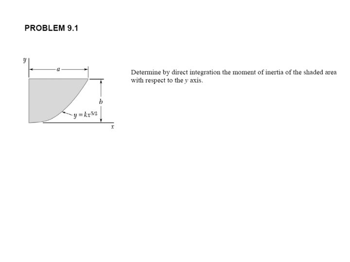
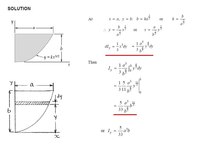
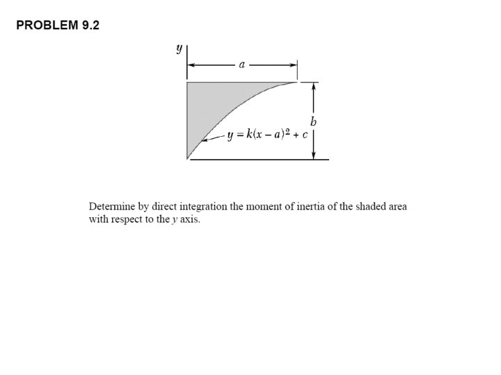
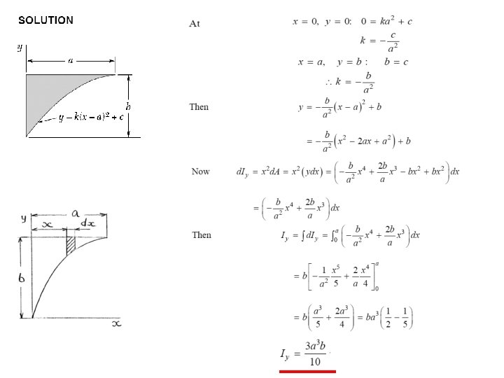
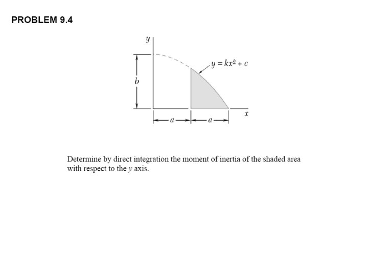
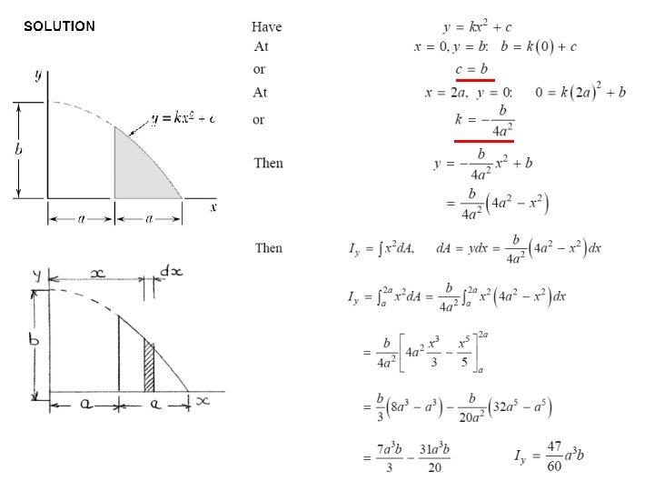
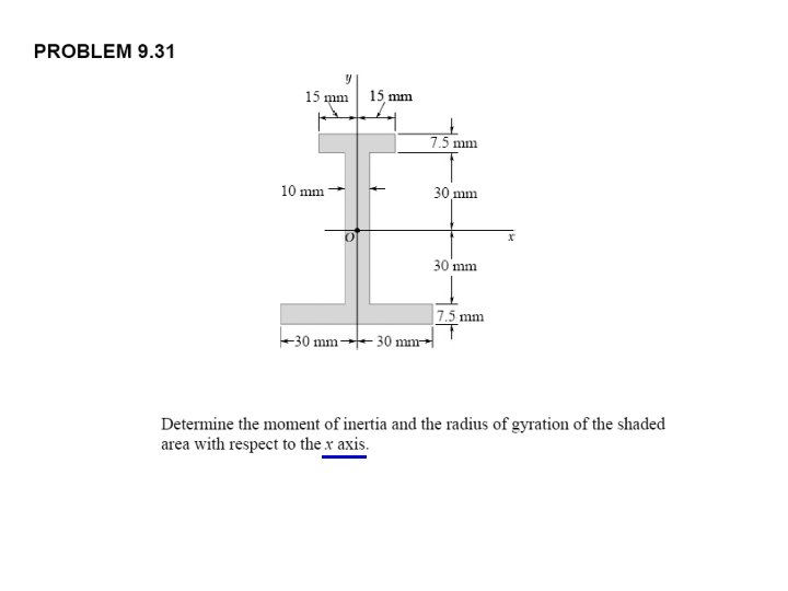
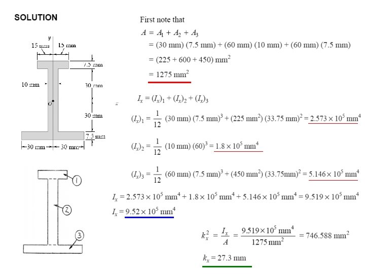
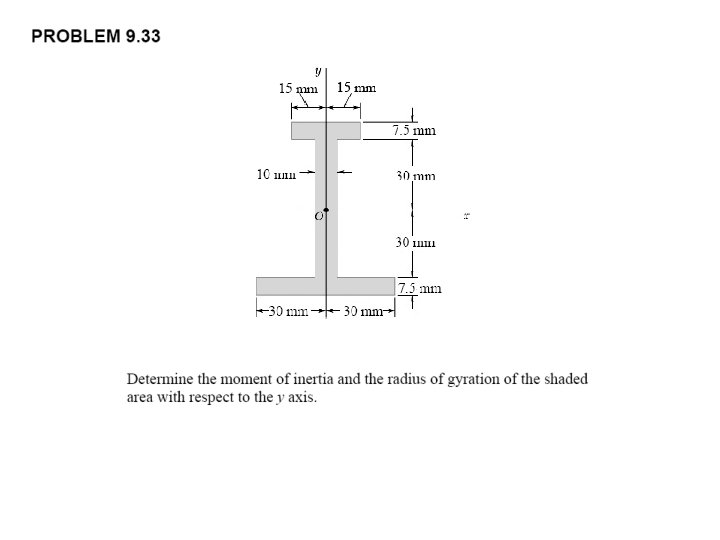
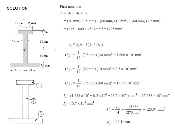
 Determine the moment of inertia of the shaded area")


- Slides: 55
CHAPTER 9 Moments of Inertia
9. 1 INTRODUCTION • Previously considered distributed forces which were proportional to the area or volume over which they act. - The resultant was obtained by summing or integrating over the areas or volumes. - The moment of the resultant about any axis was determined by computing the first moments of the areas or volumes about that axis. • Will now consider forces which are proportional to the area or volume over which they act but also vary linearly with distance from a given axis. - It will be shown that the magnitude of the resultant depends on the first moment of the force distribution with respect to the axis. - The point of application of the resultant depends on the second moment of the distribution with respect to the axis. • Current chapter will present methods for computing the moments and products of inertia for areas and masses.
9. 2 MOMENTS OF INERTIA OF AREAS • Consider distributed forces whose magnitudes are proportional to the elemental areas on which they act and also vary linearly with the distance of from a given axis. • Example: Consider a beam subjected to pure bending. Internal forces vary linearly with distance from the neutral axis which passes through the section centroid. • Example: Consider the net hydrostatic force on a submerged circular gate.
9. 3 Determination of the Moment of Inertia of an Area by Integration • Second moments or moments of inertia of an area with respect to the x and y axes, • Evaluation of the integrals is simplified by choosing d. A to be a thin strip parallel to one of the coordinate axes. • For a rectangular area, • The formula for rectangular areas may also be applied to strips parallel to the axes,
9. 4 Polar Moment of Inertia • The polar moment of inertia is an important parameter in problems involving torsion of cylindrical shafts and rotations of slabs. • The polar moment of inertia is related to the rectangular moments of inertia,
9. 5 Radius of Gyration of an Area • Consider area A with moment of inertia Ix. Imagine that the area is concentrated in a thin strip parallel to the x axis with equivalent Ix. kx = radius of gyration with respect to the x axis • Similarly,
Example For the rectangle shown in Fig 9. 8, let us compute the radius of gyration kx with respect to its base. Using formulas (9. 5) and (9. 2), we write
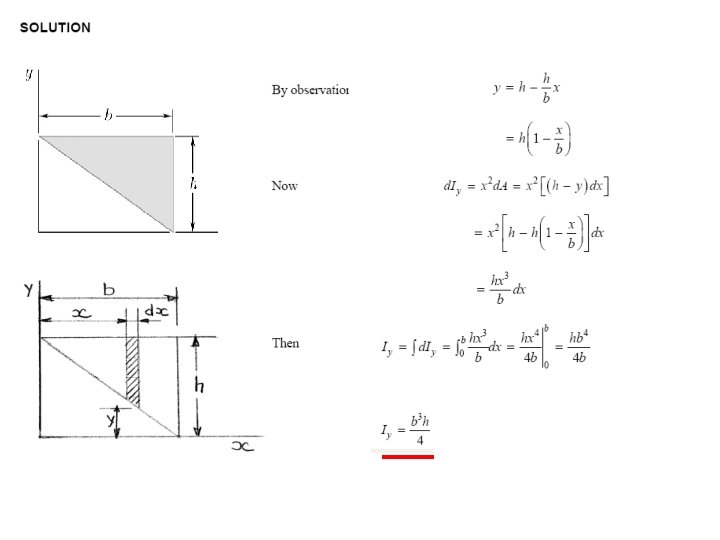
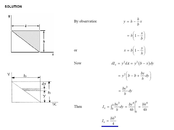
Sample Problem 9. 1 Determine the moment of inertia of a triangle with respect to its base
SOLUTION: • A differential strip parallel to the x axis is chosen for d. A. • For similar triangles, • Integrating d. Ix from y = 0 to y = h,
Sample Problem 9. 2 a) Determine the centroidal polar moment of inertia of a circular area by direct integration. b) Using the result of part a, determine the moment of inertia of a circular area with respect to a diameter.
SOLUTION: • An annular differential area element is chosen, a) Determine the centroidal polar moment of inertia of a circular area by direct integration. b) Using the result of part a, determine the moment of inertia of a circular area with respect to a diameter. • From symmetry, Ix = Iy,
Sample Problem 9. 3 a) Determine the moment of inertia of the shaded area shown with respect to each of the coordinates axes. ( properties of this area were considered
Solution Equation of the curve and the total area refer to page 225 text book SI 8 E Moment of Inertia IX
Moment of Inertia IY Radii of Gyration kx and ky
9. 6 Parallel Axis Theorem • Consider moment of inertia I of an area A with respect to the axis AA’ • The axis BB’ passes through the area centroid and is called a centroidal axis. parallel axis theorem
• Moment of inertia IT of a circular area with respect to a tangent to the circle, • Moment of inertia of a triangle with respect to a centroidal axis,
9. 7 Moment of Inertia of Composite Areas • The moment of inertia of a composite area A about a given axis is obtained by adding the moments of inertia of the component areas A 1, A 2, A 3, . . . , with respect to the same axis. moment of inertia of common geometric shapes
9. 7 Moment of Inertia of Composite Areas Properties of Rolled Steel Shapes ( SI Units )
Sample Problem 9. 4 229 mm 19 mm 352 mm 171 mm The strength of a W 360 x 44 rolled steel beam is increased by attaching a 229 x 19 mm plate to its upper flange as shown. Determine the moment of inertia and the radius of gyration of the composite section with respect to an axis which is parallel to the plate and passes through the centroid C of the section.
SOLUTION: 229 mm 19 mm 352 mm 171 mm • Determine location of the centroid of composite section with respect to a coordinate system with origin at the centroid of the beam section. • Apply the parallel axis theorem to determine moments of inertia of beam section and plate with respect to composite section centroidal axis. • Calculate the radius of gyration from the moment of inertia of the composite section.
229 mm 19 mm The origin O of the coordinates is placed at the centroid of the wide-flange shape, and the distance Y to the centroid of the composite section is computed using the methods of Chap. 5. The area of the wide-flange shape is found by referring to Fig. 9. 13 A. The area and the y coordinates of the centroid of the plane are 352 mm 171 mm 4351 185. 5 807111 5730 0 0 10081 185. 5 mm 807111
229 mm 19 mm 352 mm Moment of Inertia. The parallel-axis theorem is used to determine the moments of inertia of the wide-flange shape and the plate with respect to the x’ axis. This axis is a centroidal axis for the composite section but not for either of the elements considered separately. The value of Ix for the wide-flange shape is obtained from Fig. ). 9. 13 A For the wide-flange shape, For the plate, 171 mm For the composite area, Radius of Gyration. We have
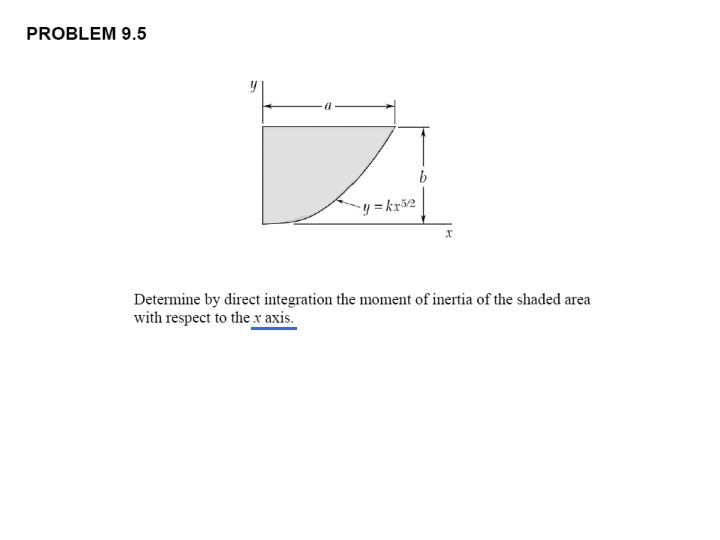
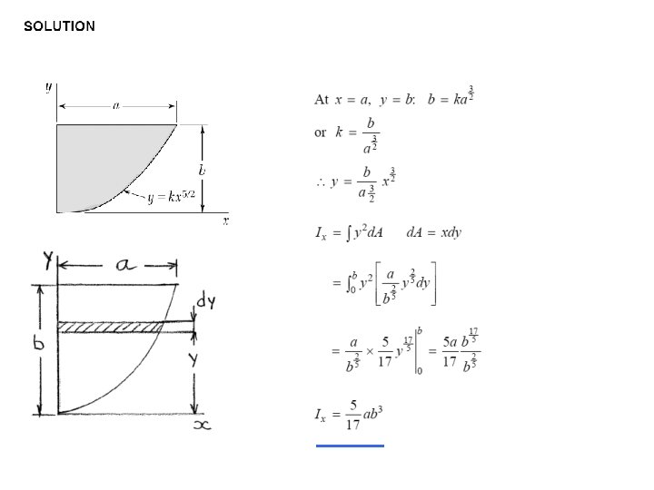
Sample Problem 9. 5 Determine the moment of inertia of the shaded area with respect to the x axis.
Solution The given area can be obtained by subtracting a half circle from a rectangle. The moments of Inertia of the rectangle and the half circle will be computed separately. 240 mm A C 120 mm a A’ x’ b Moment of Inertia of Rectangle. Referring to Fig. 9. 12, we obtain Moment of Inertia of Half Circle. Referring to Fig. 5. 8, we determine the location of the centroid C of the half circle with respect to diameter AA’. The distance b from the centroid C to the axis is
Referring now to Fig. 9. 12, we compute the moment of inertia of the half circle with respect to diameter AA’; we also compute the area of the half circle Using the parallel axis theorem , we obtain the value of Again using the parallel axis theorem, we obtain the value of
• The moment of inertia of the shaded area is obtained by subtracting the moment of inertia of the half-circle from the moment of inertia of the rectangle.
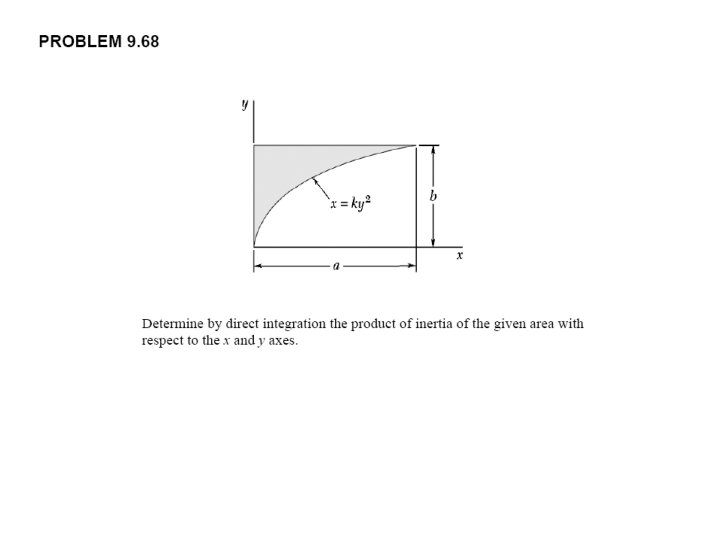
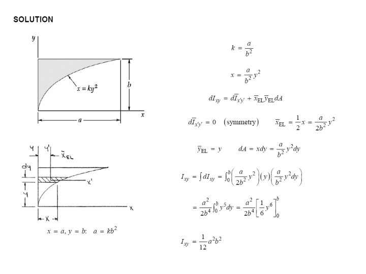
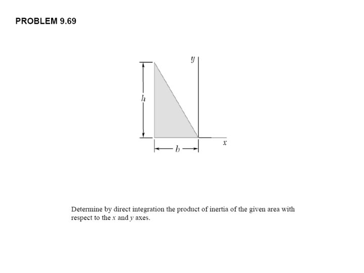
PROBLEMS
X
X
9. 8 Product of Inertia • Product of Inertia: • When the x axis, the y axis, or both are an axis of symmetry • , the product of inertia is zero.
9. 8 Product of Inertia • Parallel axis theorem for products of inertia:
Sample Problem 9. 6 Determine the product of inertia of the right triangle shown (a) with respect to the x and y axes and (b) with respect to centroidal axes parallel to the x and y axes.
Solution a. Product of Inertia Ixy A vertical rectangular strip is chosen as the differential element of area. Using the parallel-axis theorem, we write Since the element is symmetrical with respect to the x’ and y’ axes, we note that d. Ixy = 0. From the geometry of the triangle, we obtain Integrating d. Ix from x = 0 to x = b,
• Apply the parallel axis theorem to evaluate the product of inertia with respect to the centroidal axes. With the results from part a,
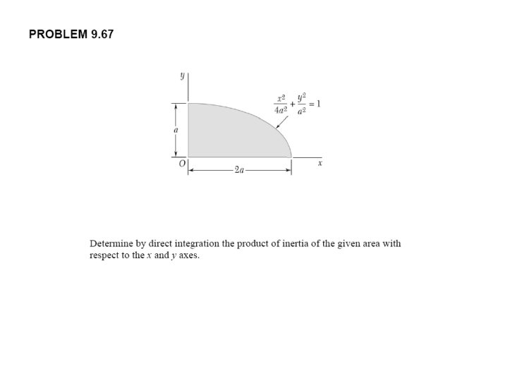
THE END