
Chapter 9 Combined Stresses 9 1 Introduction Basic
Chapter 9 Combined Stresses
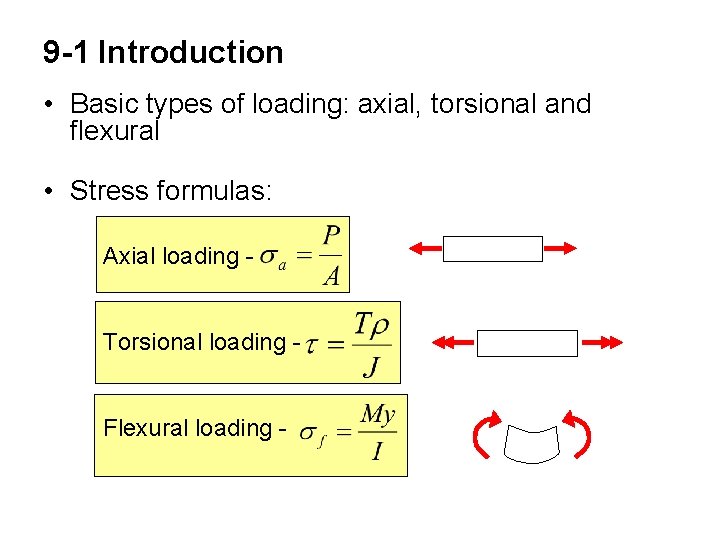
9 -1 Introduction • Basic types of loading: axial, torsional and flexural • Stress formulas: Axial loading Torsional loading Flexural loading -
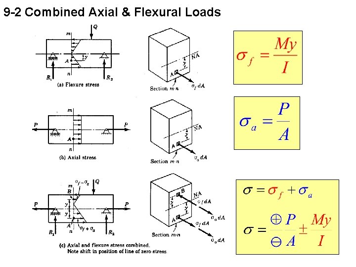
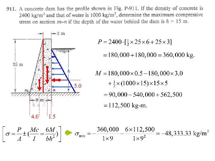
9 -2 Combined Axial & Flexural Loads
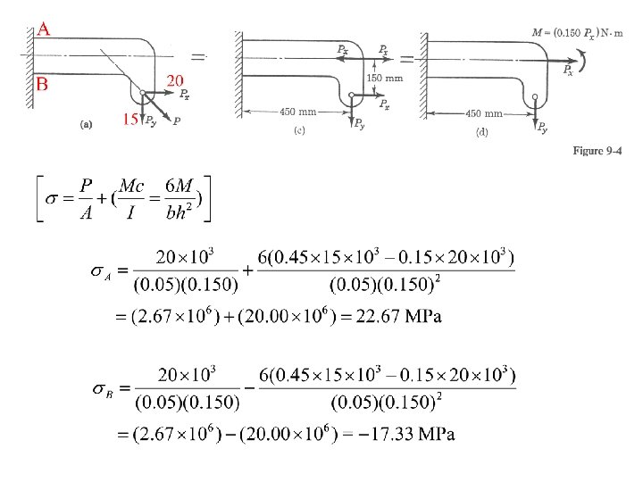
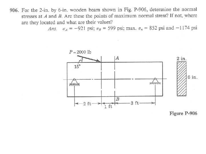
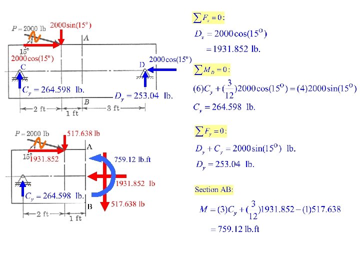

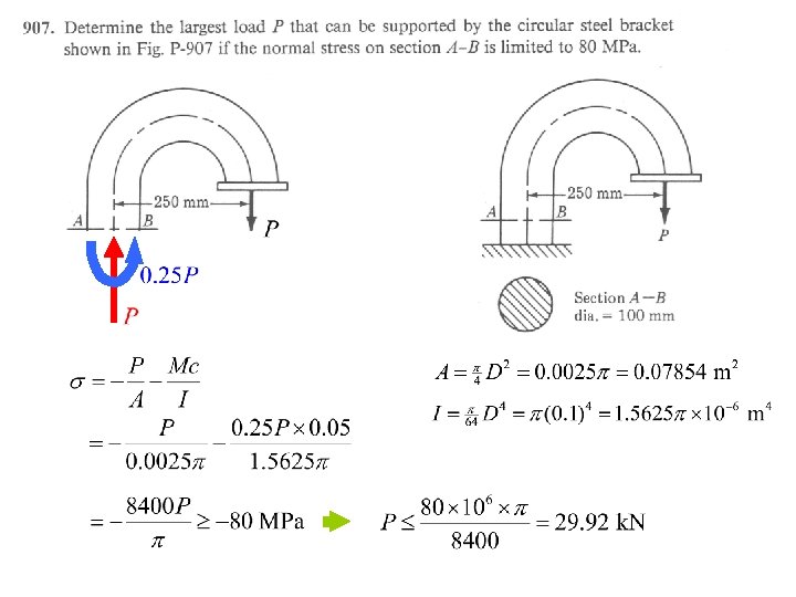
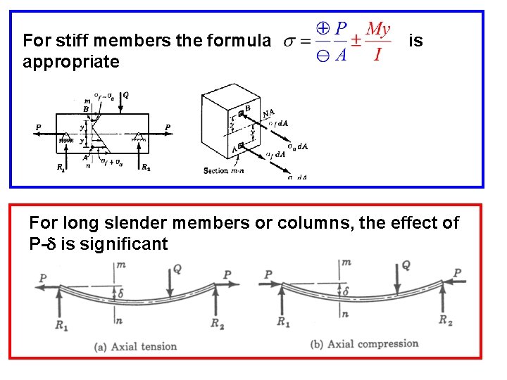
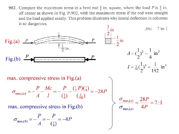
For stiff members the formula appropriate is For long slender members or columns, the effect of P-d is significant

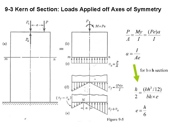
9 -3 Kern of Section: Loads Applied off Axes of Symmetry
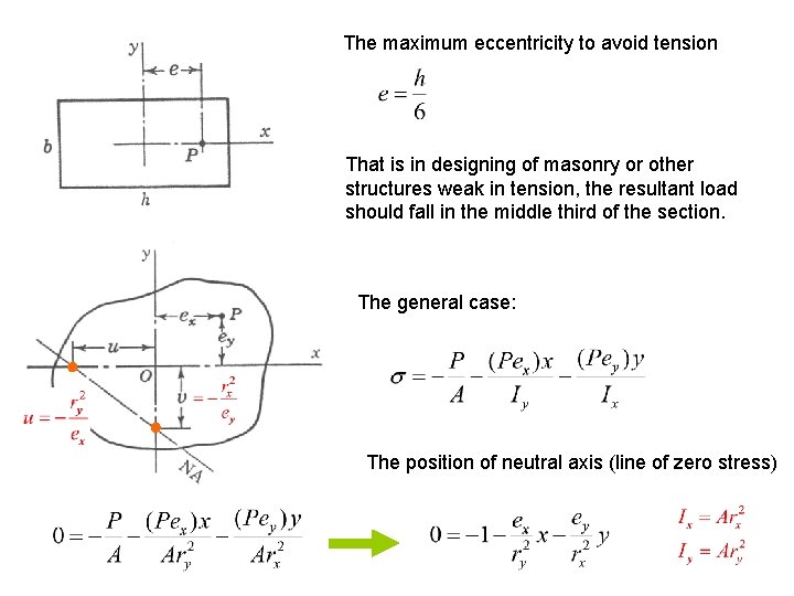
The maximum eccentricity to avoid tension That is in designing of masonry or other structures weak in tension, the resultant load should fall in the middle third of the section. The general case: The position of neutral axis (line of zero stress)
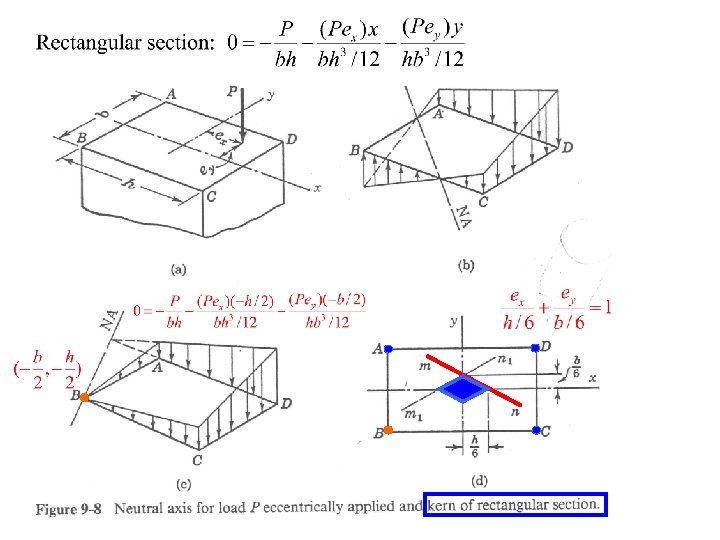
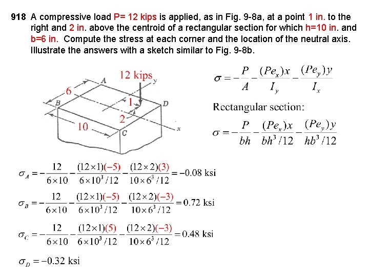
918 A compressive load P= 12 kips is applied, as in Fig. 9 -8 a, at a point 1 in. to the right and 2 in. above the centroid of a rectangular section for which h=10 in. and b=6 in. Compute the stress at each corner and the location of the neutral axis. Illustrate the answers with a sketch similar to Fig. 9 -8 b.

N. A.
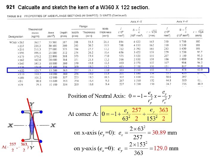
921 Calcualte and sketch the kern of a W 360 X 122 section.
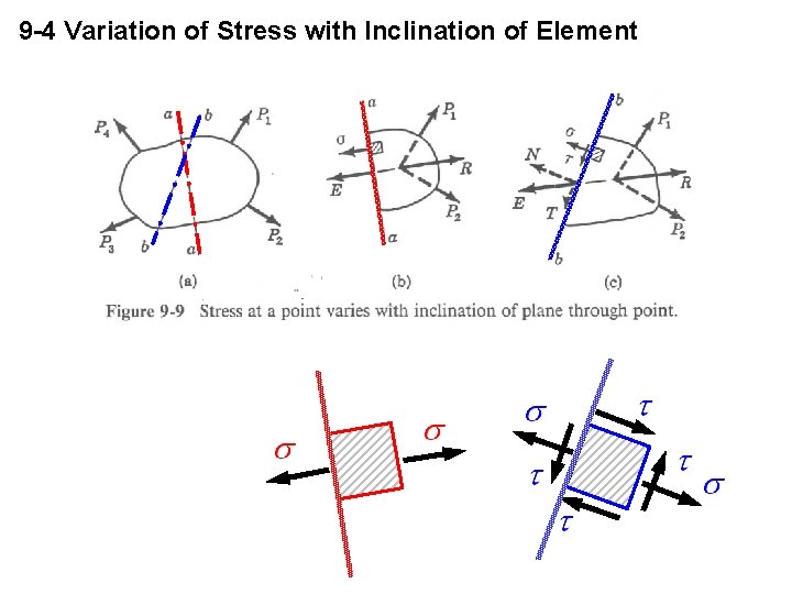
9 -4 Variation of Stress with Inclination of Element

9 -5 Stress at A Point Stress at a point really defines the uniform stress distributed over a differential area.
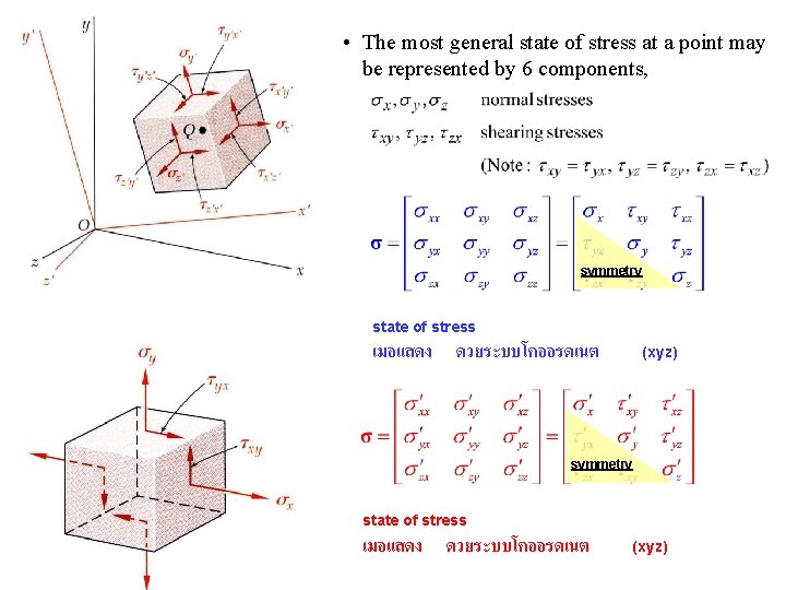
• The most general state of stress at a point may be represented by 6 components, symmetry state of stress เมอแสดง ดวยระบบโคออรดเนต (xyz)
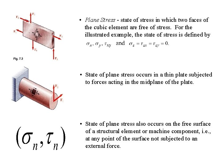
• Plane Stress - state of stress in which two faces of the cubic element are free of stress. For the illustrated example, the state of stress is defined by • State of plane stress occurs in a thin plate subjected to forces acting in the midplane of the plate. • State of plane stress also occurs on the free surface of a structural element or machine component, i. e. , at any point of the surface not subjected to an external force.
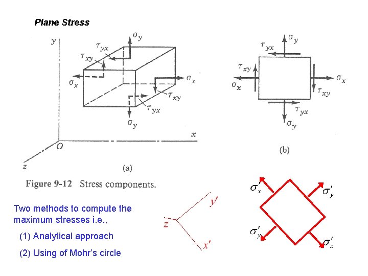
Plane Stress Two methods to compute the maximum stresses i. e. , (1) Analytical approach (2) Using of Mohr’s circle
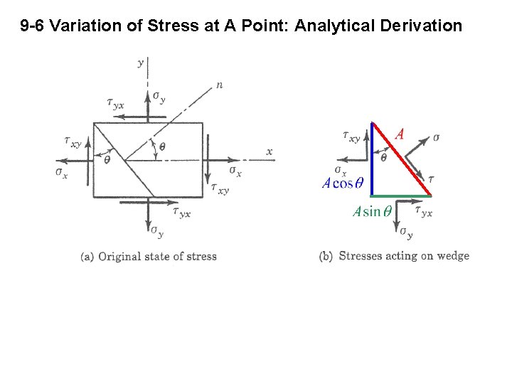
9 -6 Variation of Stress at A Point: Analytical Derivation
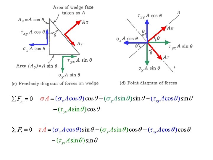
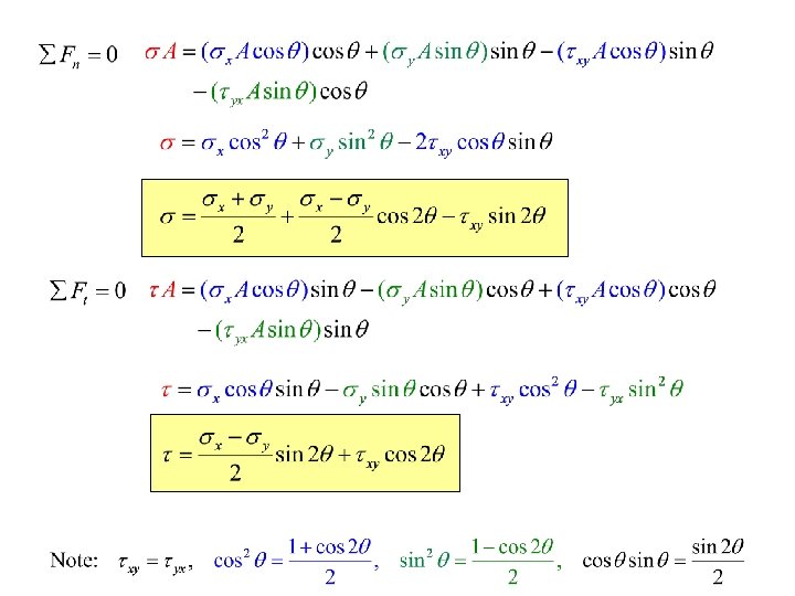
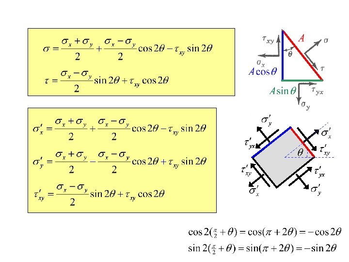
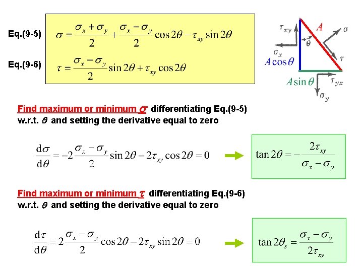
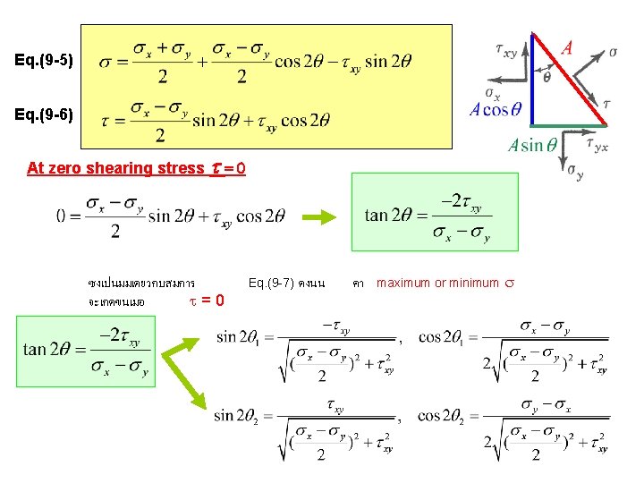
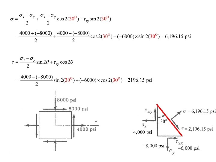
Eq. (9 -5) Eq. (9 -6) Find maximum or minimum s differentiating Eq. (9 -5) w. r. t. q and setting the derivative equal to zero Find maximum or minimum t differentiating Eq. (9 -6) w. r. t. q and setting the derivative equal to zero
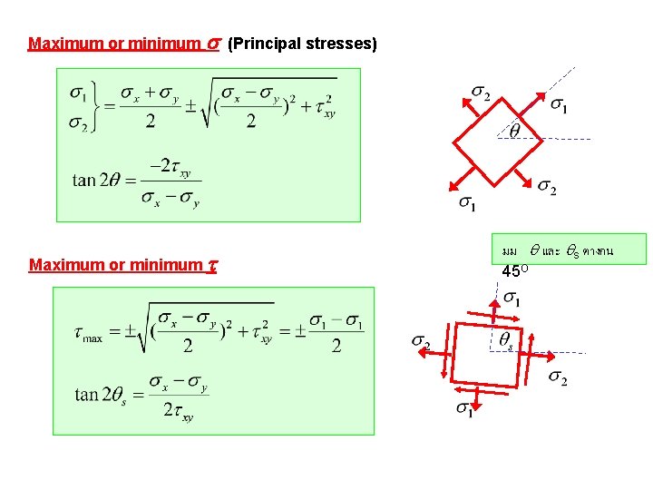
Maximum or minimum s (Principal stresses) Maximum or minimum t มม q และ qs ตางกน 45 O
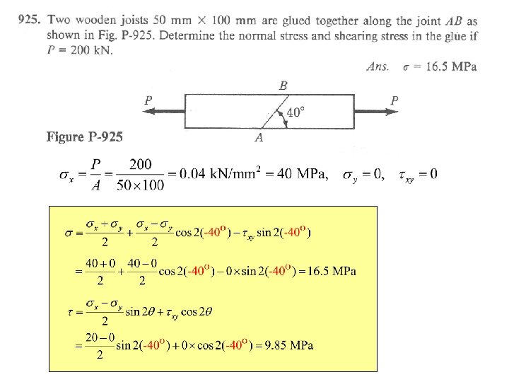
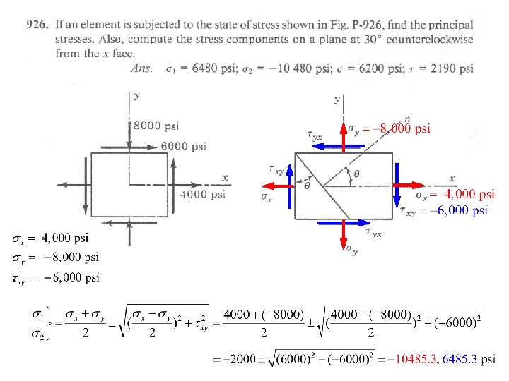
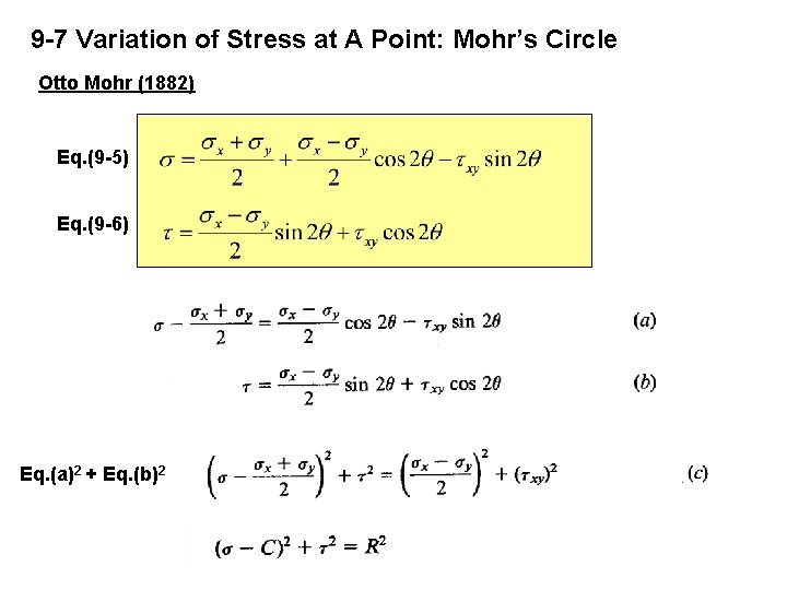
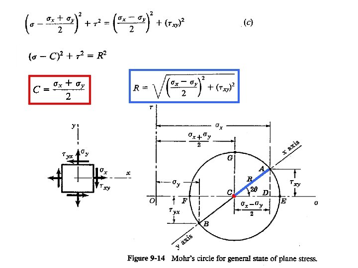
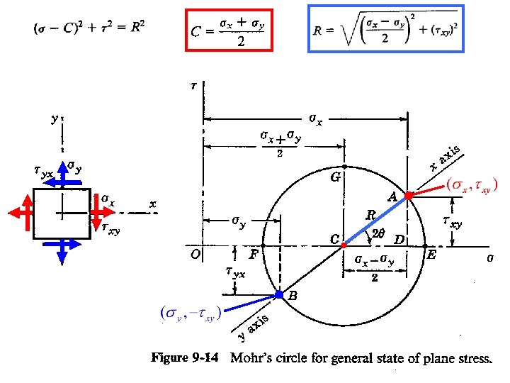
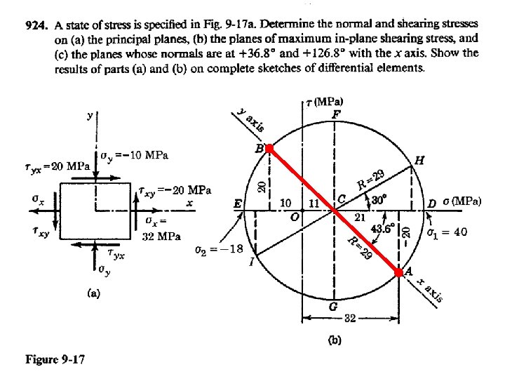
9 -7 Variation of Stress at A Point: Mohr’s Circle Otto Mohr (1882) Eq. (9 -5) Eq. (9 -6) Eq. (a)2 + Eq. (b)2
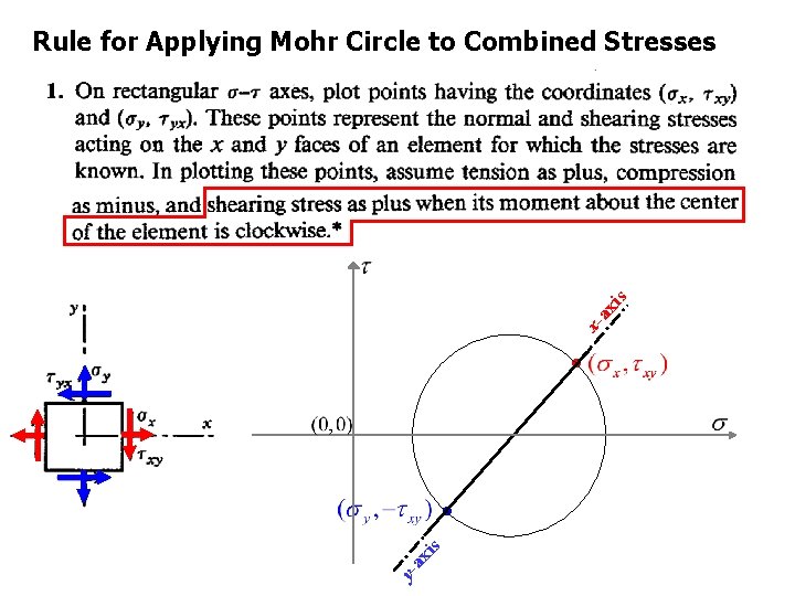
y- ax i s xa xi s Rule for Applying Mohr Circle to Combined Stresses
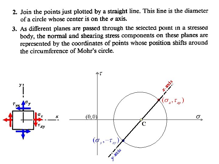
s ax i y- C s xi xa
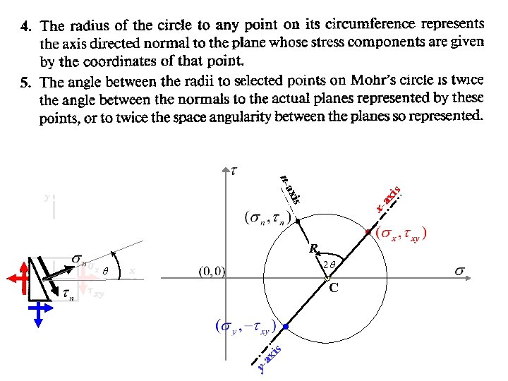
s ax i q s xi xa xis y- n-a R 2 q C
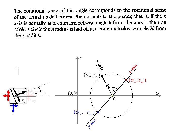
s ax i q s xi xa xis y- n-a R 2 q C
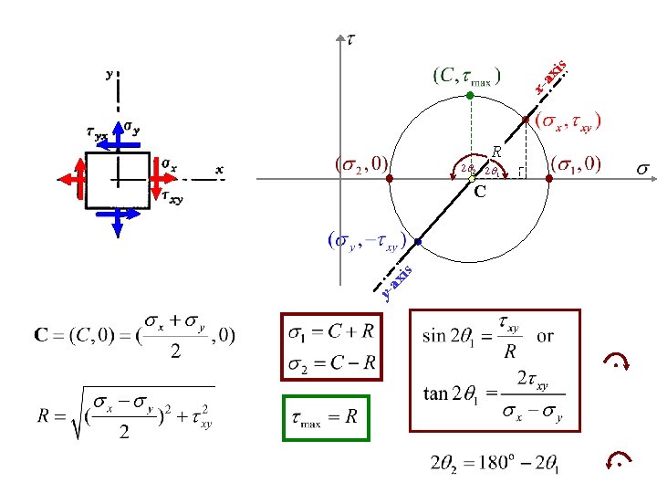
is ax y- R 2 q 2 2 q 1 C s xi xa
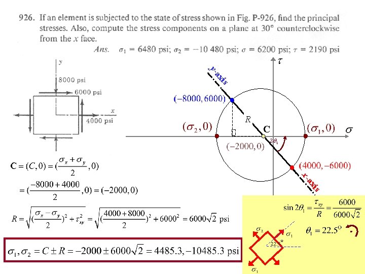
is ax y- C R 2 q 1 s xi a x-
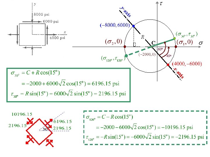
is ax y- C R 60 o 45 o s xi a x-
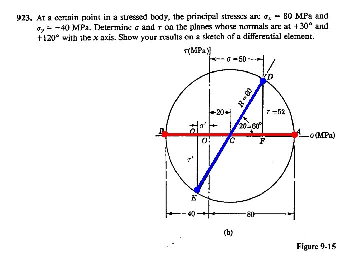
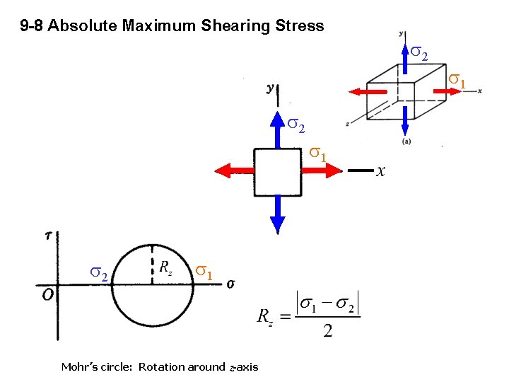
9 -8 Absolute Maximum Shearing Stress s 2 s 1 Mohr’s circle: Rotation around z-axis s 1
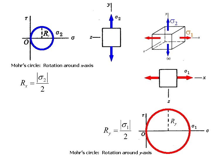
s 2 Mohr’s circle: Rotation around x-axis Mohr’s circle: Rotation around y-axis s 1
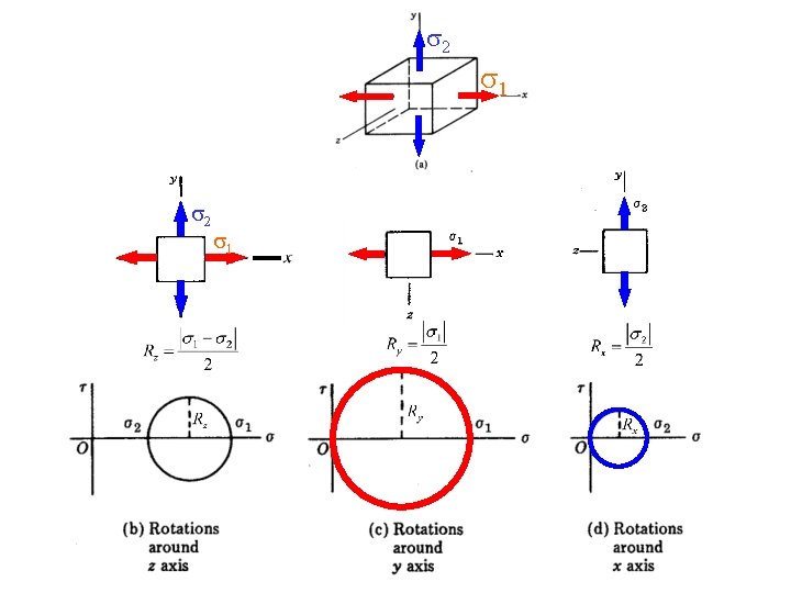
s 2 s 1
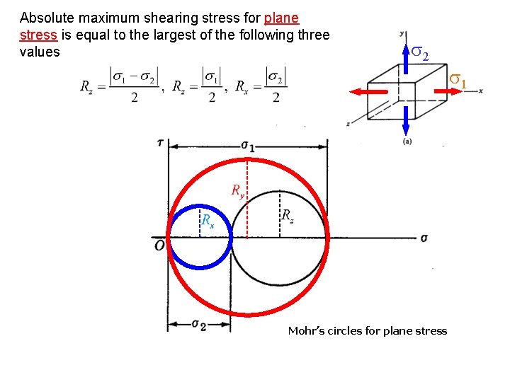
Absolute maximum shearing stress for plane stress is equal to the largest of the following three values s 2 Mohr’s circles for plane stress s 1
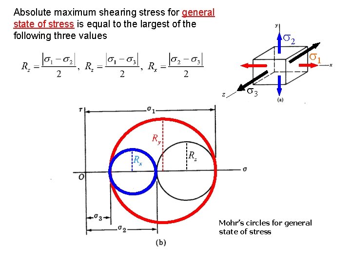
Absolute maximum shearing stress for general state of stress is equal to the largest of the following three values s 2 z s 1 s 3 Mohr’s circles for general state of stress
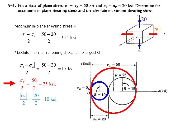
20 Maximum in-plane shearing stress = Absolute maximum shearing stress is the largest of 50
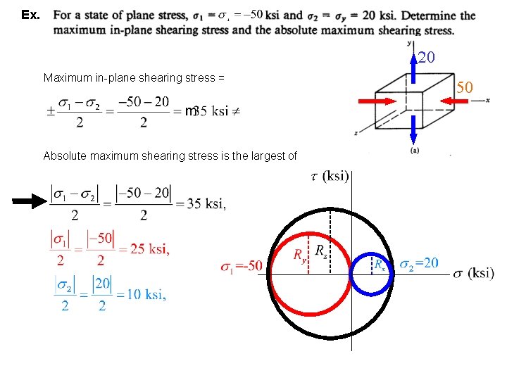
Ex. 20 Maximum in-plane shearing stress = Absolute maximum shearing stress is the largest of 50
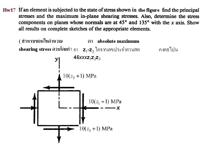
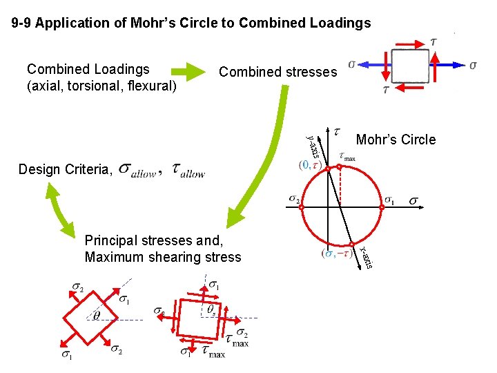
9 -9 Application of Mohr’s Circle to Combined Loadings (axial, torsional, flexural) Combined stresses is y-ax Mohr’s Circle Design Criteria, is x-ax Principal stresses and, Maximum shearing stress

Stress Trajectories
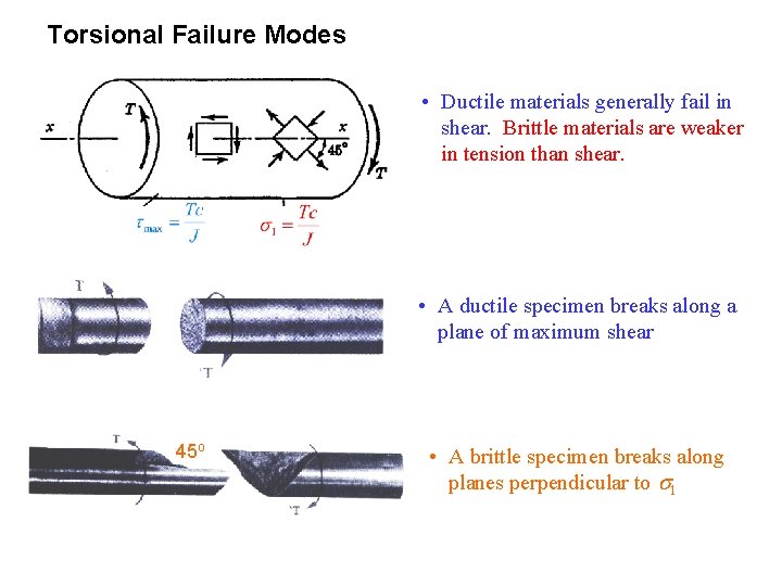
Torsional Failure Modes • Ductile materials generally fail in shear. Brittle materials are weaker in tension than shear. • A ductile specimen breaks along a plane of maximum shear 45 o • A brittle specimen breaks along planes perpendicular to s 1
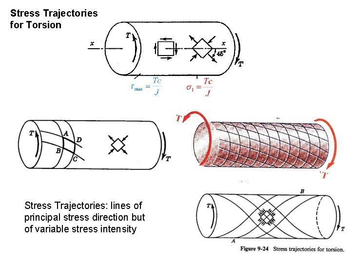
Stress Trajectories for Torsion Stress Trajectories: lines of principal stress direction but of variable stress intensity
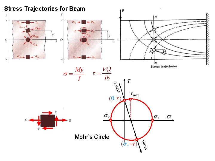
Stress Trajectories for Beam is y-ax Mohr’s Circle is x-ax
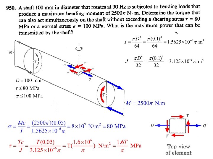
Mohr’s Circle
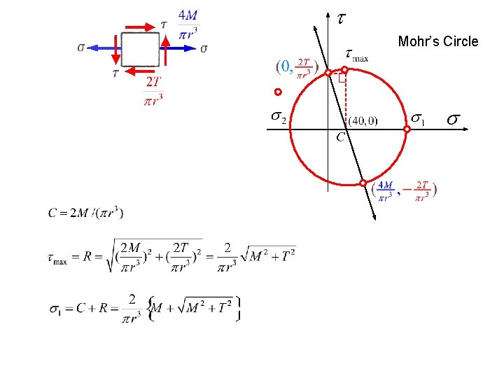
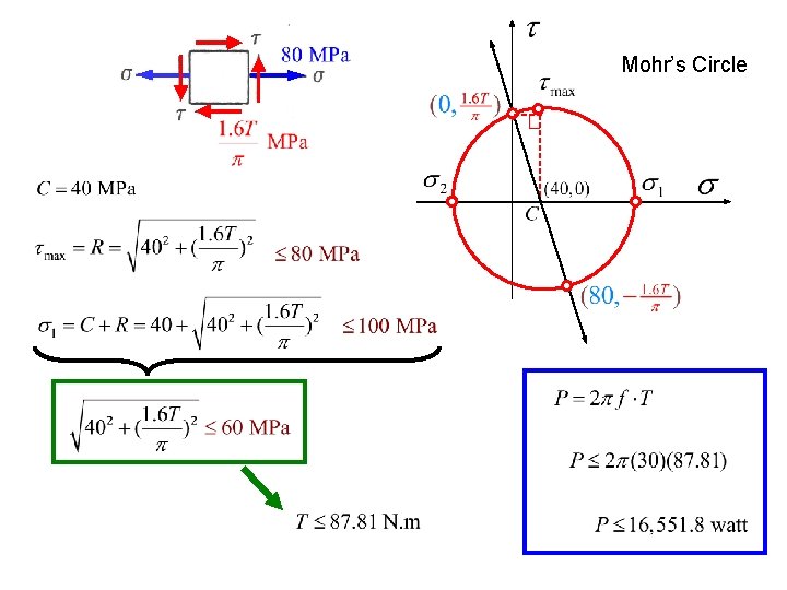
Mohr’s Circle
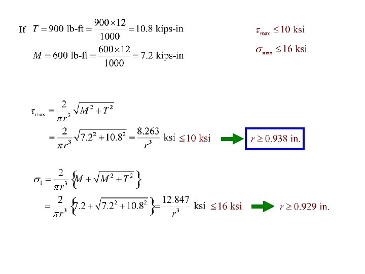
If
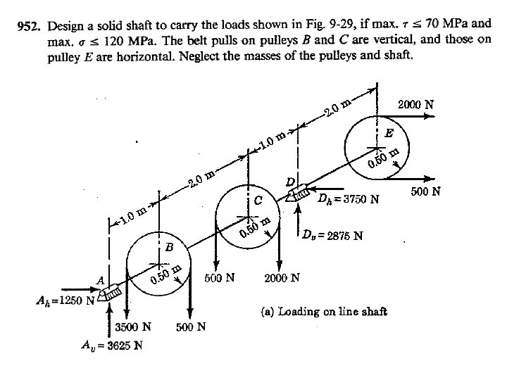
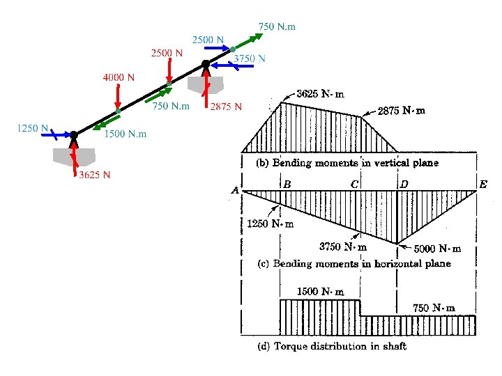
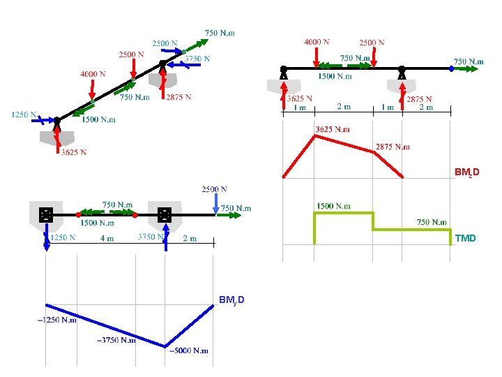
BMz. D TMD BMy. D
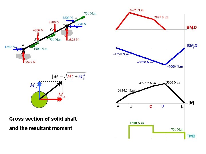
E D BMz. D C B BMy. D A A B C D E |M| Cross section of solid shaft and the resultant moment TMD
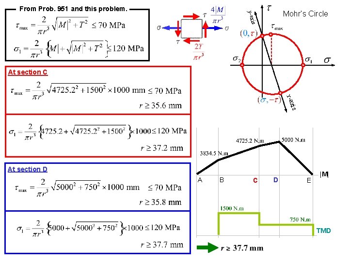
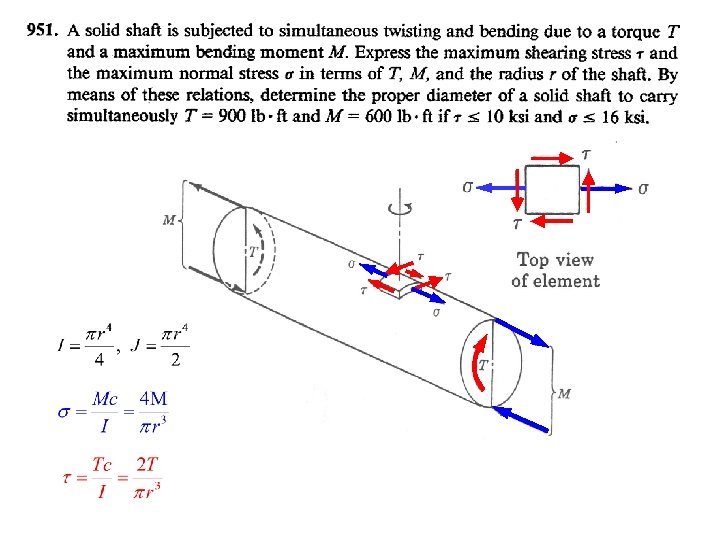
Mohr’s Circle is y-ax From Prob. 951 and this problem. BMz. D At section C BMy. D is x-ax At section D A B C D E |M| TMD
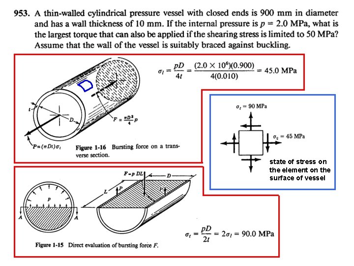
state of stress on the element on the surface of vessel
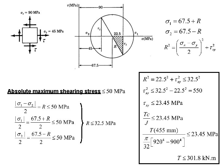
Absolute maximum shearing stress
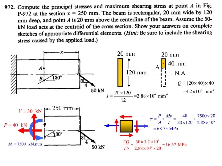
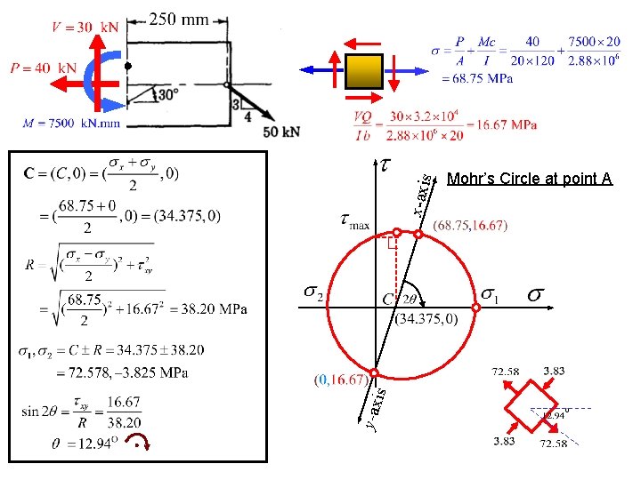
x-axis is y-ax Mohr’s Circle at point A
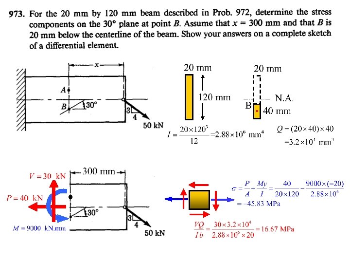
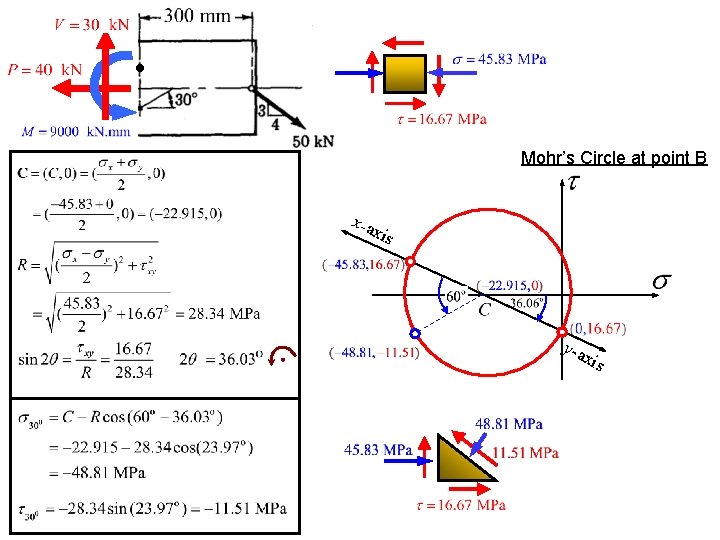
Mohr’s Circle at point B x-a xis y-a xis
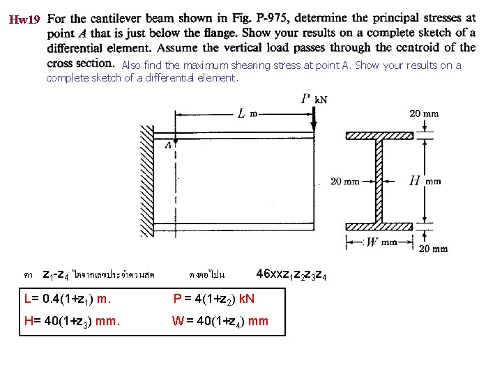
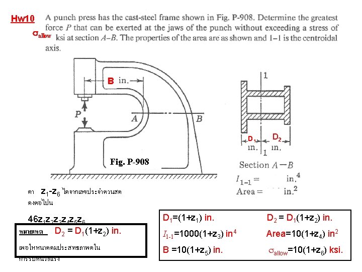
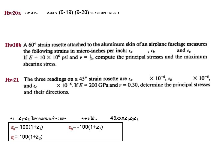
Hw 19 Also find the maximum shearing stress at point A. Show your results on a complete sketch of a differential element. คา z 1 -z 4 ไดจากเลขประจำตวนสต ดงตอไปน 46 xxz 1 z 2 z 3 z 4 L= 0. 4(1+z 1) m. P = 4(1+z 2) k. N H= 40(1+z 3) mm. W = 40(1+z 4) mm
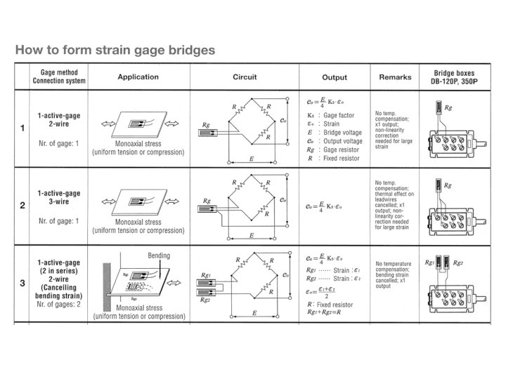
http: //www. kyowa-ei. co. jp/english/products. htm
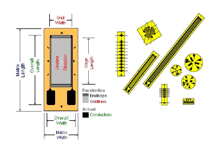
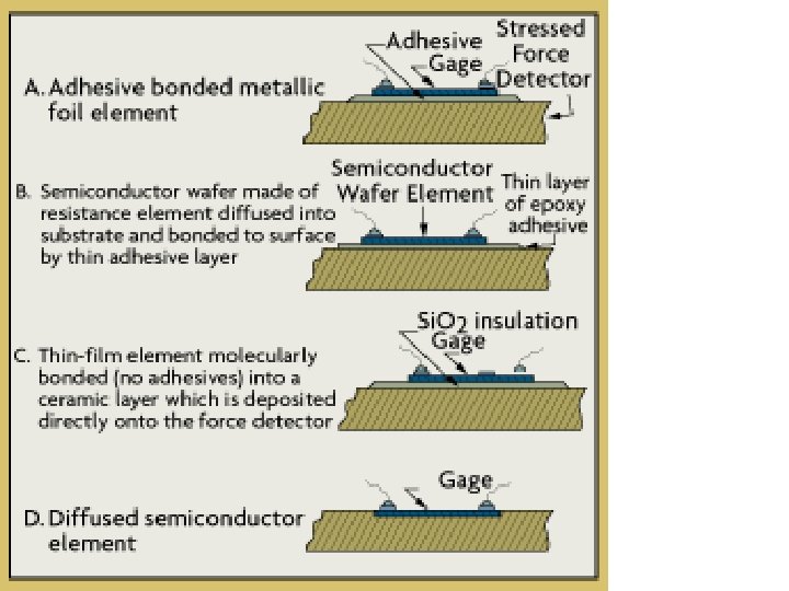
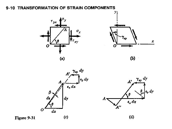
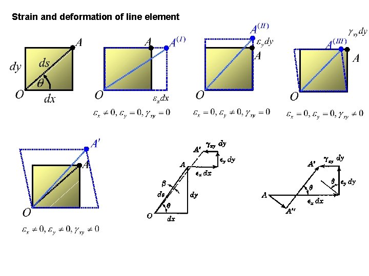
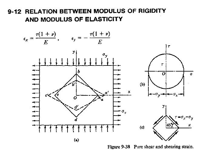
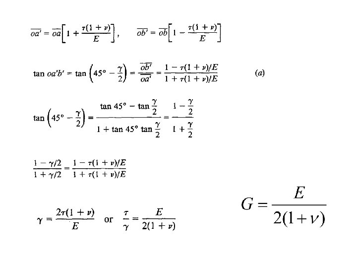
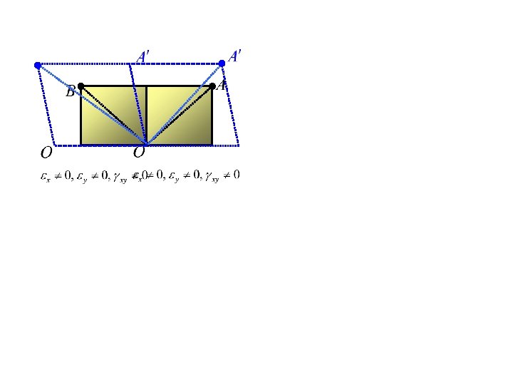
Strain and deformation of line element
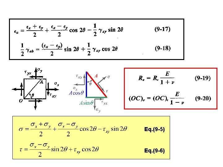
Eq. (9 -5) Eq. (9 -6)
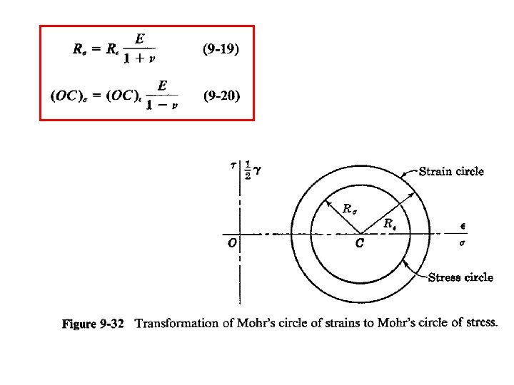
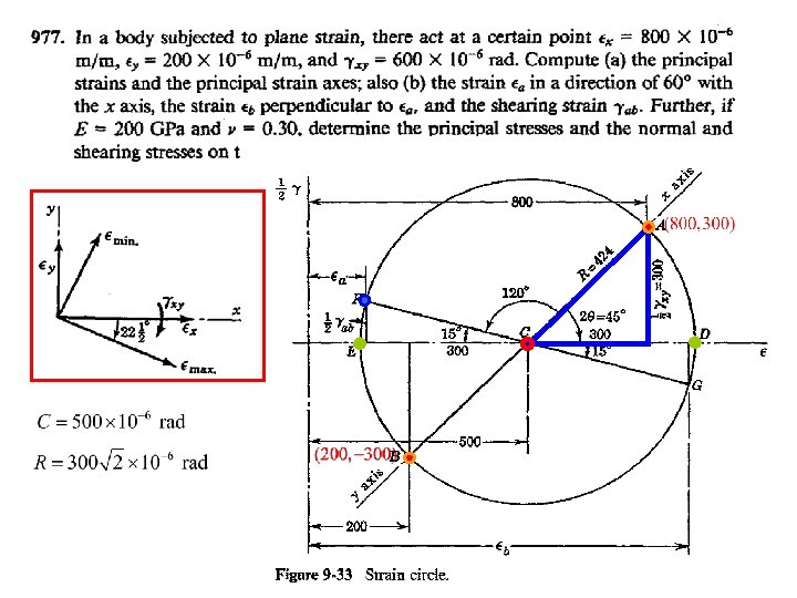
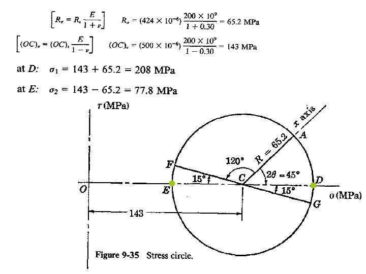
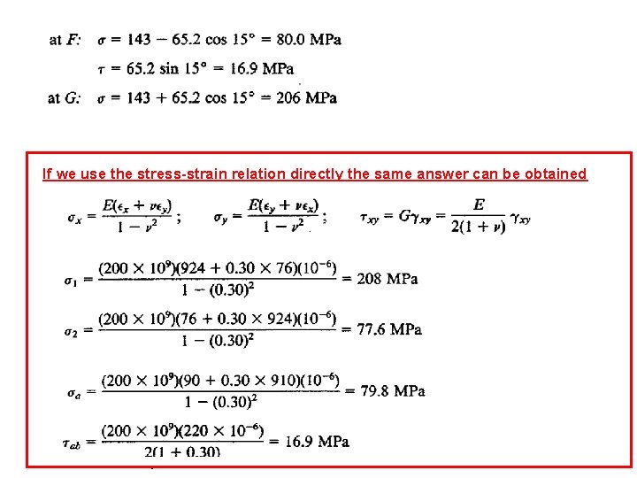
If we use the stress-strain relation directly the same answer can be obtained

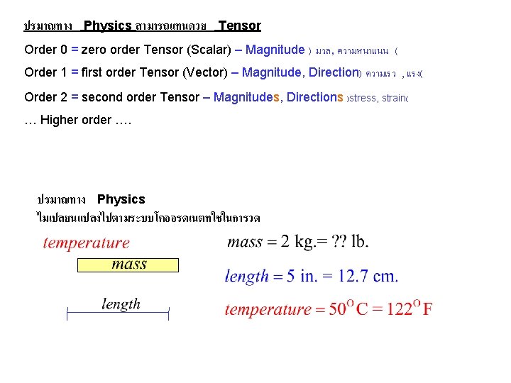
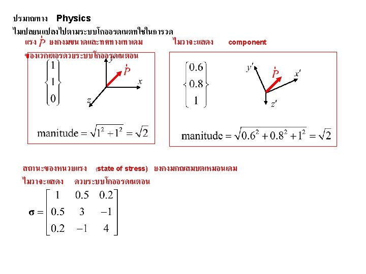
ปรมาณทาง Physics สามารถแทนดวย Tensor Order 0 = zero order Tensor (Scalar) – Magnitude ) มวล, ความหนาแนน ( Order 1 = first order Tensor (Vector) – Magnitude, Direction) ความเรว , แรง( Order 2 = second order Tensor – Magnitudes, Directions )stress, strain( … Higher order …. ปรมาณทาง Physics ไมเปลยนแปลงไปตามระบบโคออรดเนตทใชในการวด

- Slides: 103