CHAPTER 8 NONDESTRUCTIVE TEST By Noor Azira bt

CHAPTER 8 NONDESTRUCTIVE TEST By; Noor Azira bt Mohd Noor

INTRODUCTION NDT is carried out in such a manner that product integrity and surface texture remain unchanged. These techniques require considerable operator skill. Interpreting test results accurately may be difficult because the result can be subjective. However the use of computer graphic and other enhancement techniques have significantly reduced the likelihood of human error.

ULTRASONIC INSPECTION

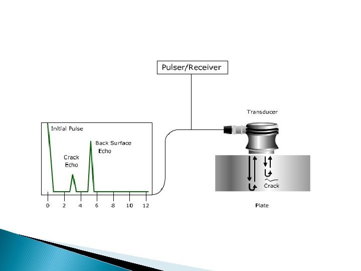
ULTRASONIC INSPECTION In ultrasonic inspection, an ultrasonic beam travels through the part. An internal defect, such as crack, interrupts the beam and reflect back a portion of the ultrasonic energy. The amplitude of the energy reflected and the time required for return, indicate the presence and location of any flaws in the work piece.
 of")
The ultrasonic waves are generated by transducers (called search unit or probes) of various type and shapes. Transducer operate on the principle of piezoelectricity using materials such as quartz, lithium sulfate or various ceramics. Most inspection carried out at a frequency range of 1 to 25 MHz. Couplants are used to transmit the ultrasonic waves from the transducer to the test piece. Typical couplant; water, oil, glycerin and grease.

The ultrasonic inspection method has high penetration power and sensitivity. It can be used from various directions to inspect flaws in large parts such as railroad wheels, pressure vessel and die blocks. This method requires experienced personnel to properly conduct the inspection and to correctly interpret the results.

ADVANTAGES It is sensitive to both surface and subsurface discontinuities. Only single-sided access is needed when the pulseecho technique is used. It is highly accurate in determining reflector position and estimating size and shape. Minimal part preparation is required. Detailed images can be produced with automated systems. It has other uses, such as thickness measurement, in addition to flaw detection.

DISADVANTAGES Surface must be accessible to transmit ultrasound. Skill and training is more extensive than with some other methods. Materials that are rough, irregular in shape, very small, exceptionally thin or not homogeneous are difficult to inspect. Cast iron and other coarse grained materials are difficult to inspect due to low sound transmission and high signal noise. Linear defects oriented parallel to the sound beam may go undetected.

Eddy Current test

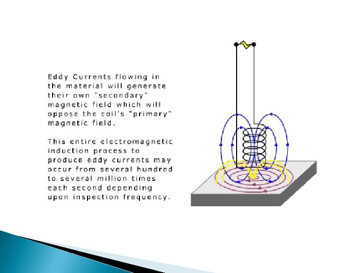
Eddy Current test The eddy-current inspection method is based on the principle of electromagnetic induction. The part is place in or adjacent to, an electric coil through which alternating current flows at frequency ranging from 60 Hz to 6 MHz. This current causes eddy current to flow in the part. Defect in the part impede and change the direction of eddy currents and cause changes in the electromagnetic field.
- the voltage of which is")
These changes affect the exciting coil (inspection coil)- the voltage of which is monitored to determine the presence flaws. Inspection coils can be made in various size and shapes to suit the geometry of the part being inspected. Parts must be electrically conductive and flaw depth detected are usually limited to 13 mm. The technique requires the use of a standard reference sample to set the sensitivity of the tester.

This shows the display when moving over a series of simulated cracks of varying depths Note that, in the example shown both the amplitude and the phase of response from the different sized cracks varies.

Depth of penetration is limited The eddy current density, and thus the strength of the response from a flaw, is greatest on the surface of the metal being tested and declines with depth. It is mathematically convenient to define the “standard depth of penetration” where the eddy current is 1/e (37%) of its surface value.

Flaws such as delaminations that lie parallel to the probe coil winding and probe scan direction are undetectable Note that cracks must interrupt the surface eddy current flow to be detected. Cracks lying parallel to the current path will not cause any significant interruption and may not be detected

One of the major advantages of eddy current as an NDT tool is the variety of inspections and measurements that can be performed. In the proper circumstances, eddy currents can be used for: ◦ ◦ Crack detection Material thickness measurements Coating thickness measurements Conductivity measurements for: Material identification Heat damage detection Case depth determination Heat treatment monitoring

ADVANTAGES Sensitive to small cracks and other defects Detects surface and near surface defects Method can be used for much more than flaw detection Minimum part preparation is required Test probe does not need to contact the part Inspects complex shapes and sizes of conductive materials

DISADVANTAGES Only conductive materials can be inspected Surface must be accessible to the probe Skill and training required is more extensive than other techniques Surface finish and roughness may interfere Depth of penetration is limited Flaws such as delaminations that lie parallel to the probe coil winding and probe scan direction are undetectable

Liquid penetrant Inspection
 is a nondestructive testing method. Used for")
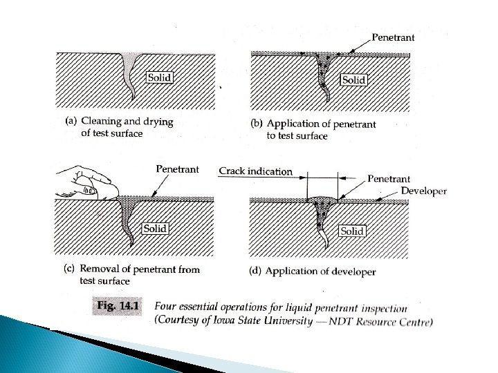
Liquid penetrant Inspection Liquid penetrant inspection (LPI) is a nondestructive testing method. Used for detecting surface discontinues such as cracks, seams, laps, cold shuts, laminations, isolated porosity through leaks in non-porous materials. The test consist of the following sequence of operations; 1) preparation of the surface to be inspected 2) application of the penetrant to the prepared surface 3) removal of the excess penetrant 4) application of a developer 5) visual examination and assessment under appropriate viewing conditions

Penetrant materials - cleaners, penetrants, removers and developers used in penetrant testing. - Liquid which when applied to a component is designed to find its way into surface discontinuities. - Remain there in detectable amounts during subsequent removal of excess penetrant from the surface.
 Colour contrast penetrant - is a solution of dyes")
- Type of penetrant. 1) Colour contrast penetrant - is a solution of dyes (typically red) in a liquid base. 2) Dual Purpose Penetrant – penetrant that gives indications which are capable of being viewed either under visible light or UV-A radiation. 3) Fluorescent Penetrant – penetrant that fluoresces under UV-A radiation.

Excess Penetrant removal - Means employed to remove excess penetrant from the test surface, without removing any penetrant from the discontinuities. - Penetrant removal operations involve the use of 1) water only 2) oil-based or water-based emulsifier 3) solvent in liquid form

Developers - Substance which has the property of withdrawing penetrant from discontinuities to make them more easily visible. - Developers; 1) dry powders 2) suspension of powder in water or solution of powder in water. 3) suspension of powder in volatile, nonaqueous solvents that are either noninflammable or flammable.

TEST PROCEDURE 1. 2. Apply the penetrant to the prepared surface with a brush, spray, electrostatic spraying, flooding, immersion and leave for a sufficient period of time to allow the penetrant to enter any discontinuity open to the surface. The penetrant time depends upon the - properties of the penetrant - the test temp. - the test material - specific defects

3. Remove the excess penetrant with a clean, dry, absorbent lint-free cloth or with paper towels 4. To ensure the retention of penetrant in the discontinous. 5. Insufficient removal of the penetrant will leave a background which will interfere with the subsequent indication of discontinuities. 6. For fluorescent penetrant inspection, check the cleaning under ultraviolet radiation. 7. For visible dye penetrant inspection, continue the cleaning until no visible evidence of the coloured dye remains in the surface.

8. Uniformly apply a developer, to the test surface within the period. 9. The developer may be applied - spraying - electrostatic spraying - flow-on technique - immersion 10. After applying the developer, allow the part to stand for a sufficient time for any indications to appear.

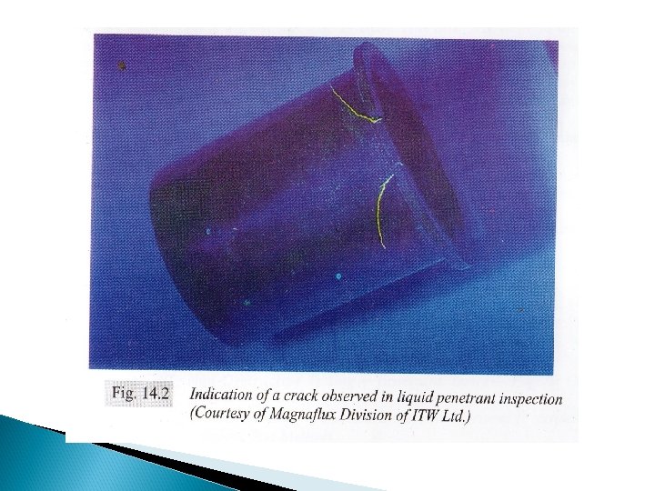
11. This time will depend upon the testing media being used, the materials examined and the nature of the defects present. 12. When the development time has elapsed, examine the test surface with naked eye and access it under appropriate viewing conditions. 13. Record the presence of continuities, if any. 14. Discontinuities will appear as spots or lines. 15. After inspection. Clean surface and if necessary apply a corrosion preventative.

Magnetic Particle
 is a nondestructive testing method used for defect detection")
INTRODUCTION Magnetic particle inspection (MPI) is a nondestructive testing method used for defect detection of linear, surface and near surface discontinuities in ferromagnetic test materials. Ferromagnetic materials are strongly attracted to a magnet and can easily be magnetized. Materials such as iron, nickel and cobalt. This testing method is based on the principle that magnetic flux in a magnetized object is locally distorted by the presence of a discontinuity.

OPERATION Liquid solution such as Paraffin which contains ferromagnetic powder is sprayed on the welding surface. To produce a clear color differences, the powder is colored or black. Sometimes fluorescent dye solution was used. This solution can be clearly seen under ultra-violet light.

Work piece is magnetize by flowing an electric current through the work piece Un-magnetized material Magnetized material Once the work piece is magnetized, a magnetic field with flux lines or magnetic force is produced on the surface of the work piece.

If there is an defect on surface of the work piece, the flux lines will be disturbed. An independent magnetic dipoles will be produces at both ends of defect-north and south dipoles. The iron particles will be concentrated on both dipoles.

YOKE- to produce magnetic field when magnetized the workpiece.

MAGNETIC PARTICLES Key ingredient as they form the indications that alert the inspector to defects. The metal used for the particles has high magnetic permeability and low retentivity. Have two types : -Dry magnetic particles -Wet magnetic particles


ADVANTAGES High sensitivity method for ferromagnetic materials Defects on and below the surface will be detected Reliable, fast and economic method

DISADVANTAGES Application only to ferromagnetic materials. Parts should be clean before and after inspection. Some applications require parts to be demagnetised after inspection.

APPLICATION Suitable for pointing out surface or subcortical defects: such as cracks, inclusions, and pinching. Most weld discontinuities open to or near the surface. Most suitable for cracks and other linear conditions.

OTHER APPLICATION Structural steel Automotive Petrochemical Power generation Aerospace industries. Underwater inspection such as offshore structures and underwater pipelines.

Flaw Detector test

DEFINITION Sound waves are simply organized mechanical vibrations traveling through a medium, which may be a solid, a liquid, or a gas. These waves will travel through a given medium at a specific speed or velocity, in a predictable direction, and when they encounter a boundary with a different medium they will be reflected or transmitted according to simple rules. This is the principle of physics that underlies ultrasonic flaw detection.

OPERATION Straight Beam Testing Straight beam testing utilizing contact, delay line, dual element, or immersion transducers is generally employed to find cracks or delaminations parallel to the surface of the test piece, as well as voids and porosity. It utilizes the basic principle that sound energy traveling through a medium will continue to propagate until it either disperses or reflects off a boundary with another material, such as the air surrounding a far wall or found inside a crack.

In this type of test, the operator couples the transducer to the test piece and locates the echo returning from the far wall of the test piece, and then looks for any echoes that arrive ahead of that backwall echo discounting grain scatter noise if present. An acoustically significant echo that precedes the backwall echo implies the presence of a laminar crack or void. Through further analysis, the depth, size, and shape of the structure producing the reflection can be determined.

Sound energy will travel to the far side of a part, but reflect earlier if a laminar crack or similar discontinuity is presented.

Angle Beam Testing • Cracks or other discontinuities perpendicular to the surface of a test piece, or tilted with respect to that surface, are usually invisible with straight beam test techniques because of their orientation with respect to the sound beam. • Such defects can occur in welds, in structural metal parts, and many other critical components. • To find them, angle beam techniques are used, employing either common angle beam (wedge) transducer assemblies or immersion transducers aligned so as to direct sound energy into the test piece at a selected angle. • The use of angle beam testing is especially common in weld inspection.

Typical angle beam assemblies make use of mode conversion and Snell's Law to generate a shear wave at a selected angle (most commonly 30, 45, 60, or 70 degrees) in the test piece. As the angle of an incident longitudinal wave with respect to a surface increases, an increasing portion of the sound energy is converted to a shear wave in the second material if the angle is high enough, all of the energy in the second material will be in the form of shear waves.

ADVANTAGES Depth of penetration for flaw detection or measurement is superior to other methods. Only single sided access is required. Provides distance information. Minimum part preparation is required. Method can be used for much more than just flaw detection.

DISADVANTAGES Surface must be accessible to probe and couplant. Skill and training required is more extensive than other technique. Surface finish and roughness can interfere with inspection. Thin parts may be difficult to inspect. Linear defects oriented parallel to the sound

APPLICATION Testing for surface cracks on aircraft engines and airframes Simple material sorting tasks Surface crack detection on bars or tubes or on manufactured components Flaw detect resolution to approximately 20 µm (0. 0008 inch)
- Slides: 53