
Chapter 8 Mechanical Properties of Metals ISSUES TO

- Slides: 34
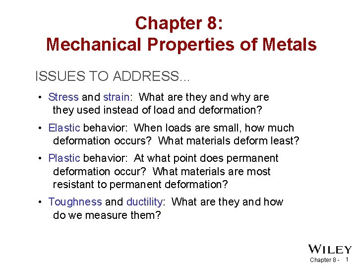
Chapter 8: Mechanical Properties of Metals ISSUES TO ADDRESS. . . • Stress and strain: What are they and why are they used instead of load and deformation? • Elastic behavior: When loads are small, how much deformation occurs? What materials deform least? • Plastic behavior: At what point does permanent deformation occur? What materials are most resistant to permanent deformation? • Toughness and ductility: What are they and how do we measure them? Chapter 8 - 1
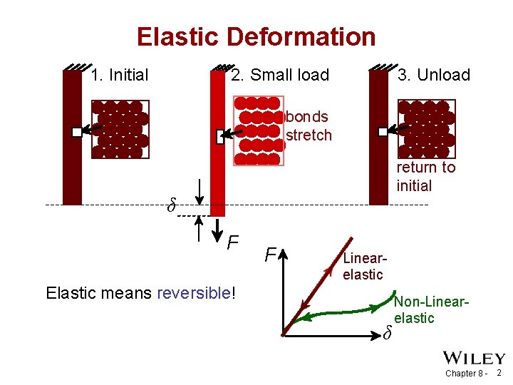
Elastic Deformation 1. Initial 3. Unload 2. Small load bonds stretch return to initial δ F F Linearelastic Elastic means reversible! δ Non-Linearelastic Chapter 8 - 2
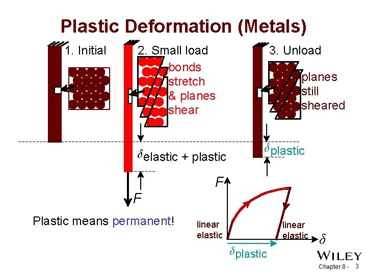
Plastic Deformation (Metals) 1. Initial 2. Small load bonds stretch & planes shear δ elastic + plastic 3. Unload planes still sheared δ plastic F F Plastic means permanent! linear elastic δ plastic δ Chapter 8 - 3
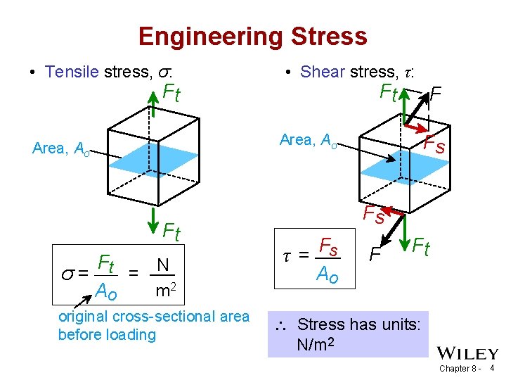
Engineering Stress • Tensile stress, σ: Ft • Shear stress, τ: Ft F Area, Ao Ft Ft = N σ= m 2 Ao original cross-sectional area before loading Fs Fs F τ = s Ao F Ft Stress has units: N/m 2 Chapter 8 - 4
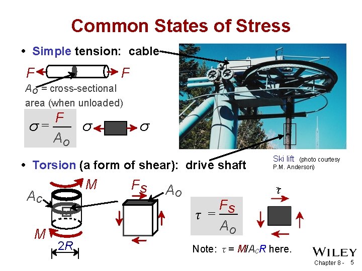
Common States of Stress • Simple tension: cable F F A o = cross-sectional area (when unloaded) F σ= σ Ao σ • Torsion (a form of shear): drive shaft M Ac M 2 R Fs Ao Ski lift (photo courtesy P. M. Anderson) τ Fs τ = Ao Note: τ = M/Ac. R here. Chapter 8 - 5
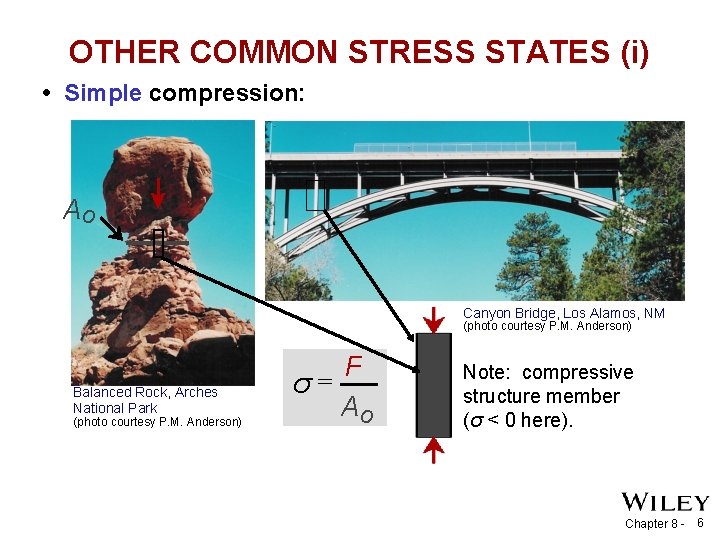
OTHER COMMON STRESS STATES (i) • Simple compression: Ao Canyon Bridge, Los Alamos, NM (photo courtesy P. M. Anderson) Balanced Rock, Arches National Park (photo courtesy P. M. Anderson) F σ= Ao Note: compressive structure member (σ < 0 here). Chapter 8 - 6
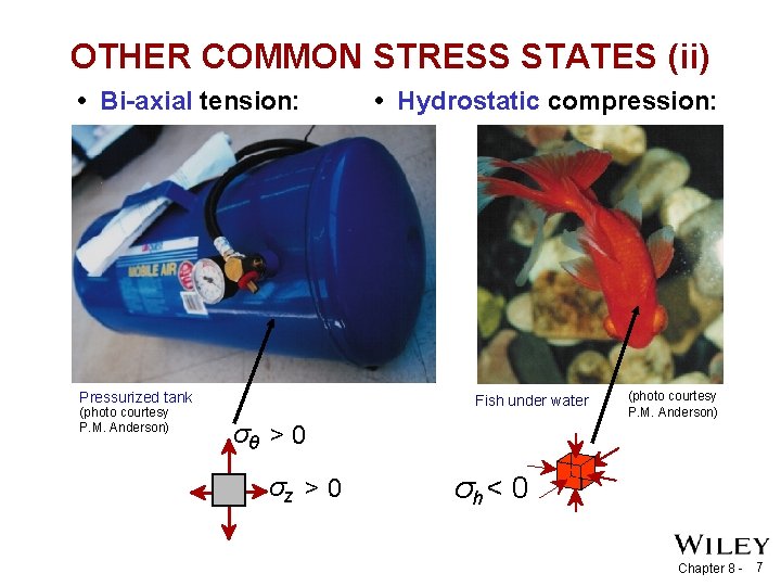
OTHER COMMON STRESS STATES (ii) • Bi-axial tension: Pressurized tank (photo courtesy P. M. Anderson) • Hydrostatic compression: Fish under water (photo courtesy P. M. Anderson) σθ > 0 σz > 0 σh < 0 Chapter 8 - 7
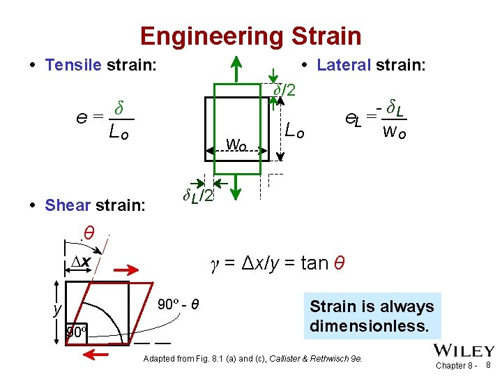
Engineering Strain • Tensile strain: • Lateral strain: δ /2 e= δ Lo wo • Shear strain: - δL e. L = wo Lo δ L /2 θ x γ = Δx/y = tan θ 90º - θ y 90º Strain is always dimensionless. Adapted from Fig. 8. 1 (a) and (c), Callister & Rethwisch 9 e. Chapter 8 - 8
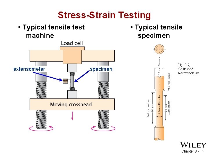
Stress-Strain Testing • Typical tensile specimen • Typical tensile test machine extensometer specimen Fig. 8. 2, Callister & Rethwisch 9 e. Chapter 8 - 9
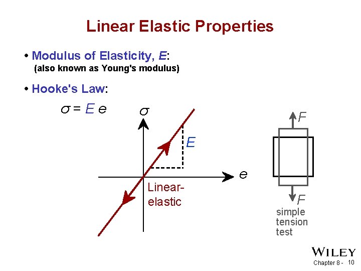
Linear Elastic Properties • Modulus of Elasticity, E: (also known as Young's modulus) • Hooke's Law: σ=Ee σ F E Linearelastic e F simple tension test Chapter 8 - 10
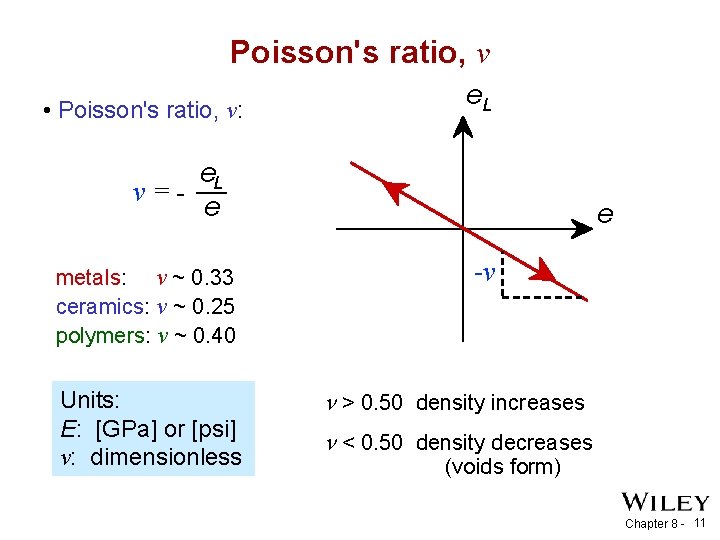
Poisson's ratio, ν • Poisson's ratio, ν: e. L ν =e metals: ν ~ 0. 33 ceramics: ν ~ 0. 25 polymers: ν ~ 0. 40 Units: E: [GPa] or [psi] ν: dimensionless e -ν > 0. 50 density increases < 0. 50 density decreases (voids form) Chapter 8 - 11
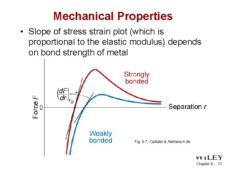
Mechanical Properties • Slope of stress strain plot (which is proportional to the elastic modulus) depends on bond strength of metal Fig. 8. 7, Callister & Rethwisch 9 e. Chapter 8 - 12
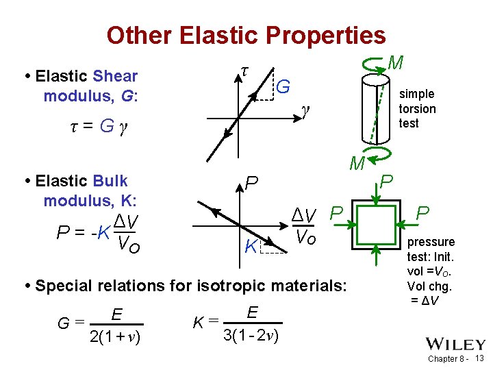
Other Elastic Properties • Elastic Shear modulus, G: τ M G γ τ=Gγ • Elastic Bulk modulus, K: ΔV P = -K Vo M P K ΔV P Vo • Special relations for isotropic materials: E G= 2(1 + ν) simple torsion test E K= 3(1 - 2ν) P P pressure test: Init. vol =Vo. Vol chg. = ΔV Chapter 8 - 13
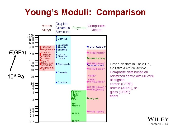
Young’s Moduli: Comparison Metals Alloys 1200 1000 800 600 400 E(GPa) 200 100 80 60 40 109 Pa Graphite Composites Ceramics Polymers /fibers Semicond Diamond Tungsten Molybdenum Steel, Ni Tantalum Platinum Cu alloys Zinc, Ti Silver, Gold Aluminum Magnesium, Tin Si carbide Al oxide Si nitride Carbon fibers only CFRE(|| fibers)* <111> Si crystal Aramid fibers only <100> AFRE(|| fibers)* Glass -soda Glass fibers only GFRE(|| fibers)* Concrete GFRE* 20 10 8 6 4 2 1 0. 8 0. 6 0. 4 0. 2 CFRE* GFRE( fibers)* Graphite Polyester PET PS PC CFRE( fibers) * AFRE( fibers) * Epoxy only Based on data in Table B. 2, Callister & Rethwisch 9 e. Composite data based on reinforced epoxy with 60 vol% of aligned carbon (CFRE), aramid (AFRE), or glass (GFRE) fibers. PP HDPE PTFE LDPE Wood( grain) Chapter 8 - 14
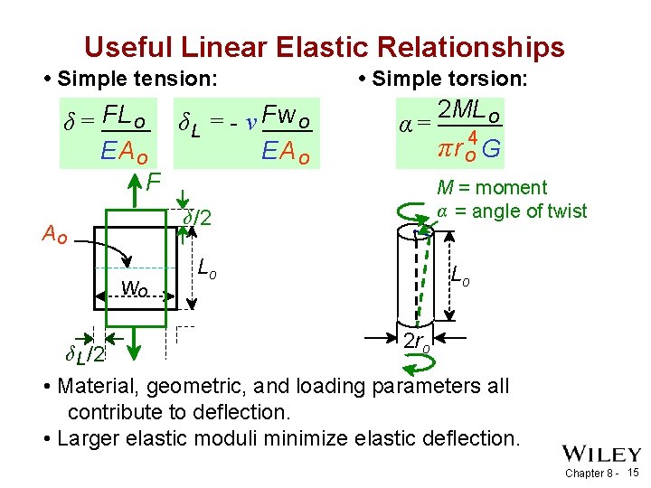
Useful Linear Elastic Relationships • Simple tension: δ = FL o δ L = - ν Fw o EA o F α= wo 2 ML o π r o 4 G M = moment α = angle of twist δ /2 Ao δ L /2 • Simple torsion: Lo Lo 2 ro • Material, geometric, and loading parameters all contribute to deflection. • Larger elastic moduli minimize elastic deflection. Chapter 8 - 15
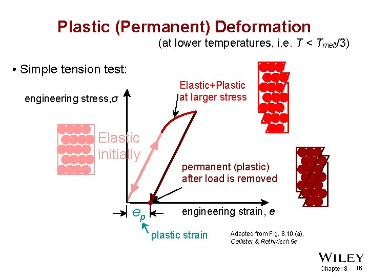
Plastic (Permanent) Deformation (at lower temperatures, i. e. T < Tmelt/3) • Simple tension test: Elastic+Plastic at larger stress engineering stress, σ Elastic initially ep permanent (plastic) after load is removed engineering strain, e plastic strain Adapted from Fig. 8. 10 (a), Callister & Rethwisch 9 e. Chapter 8 - 16
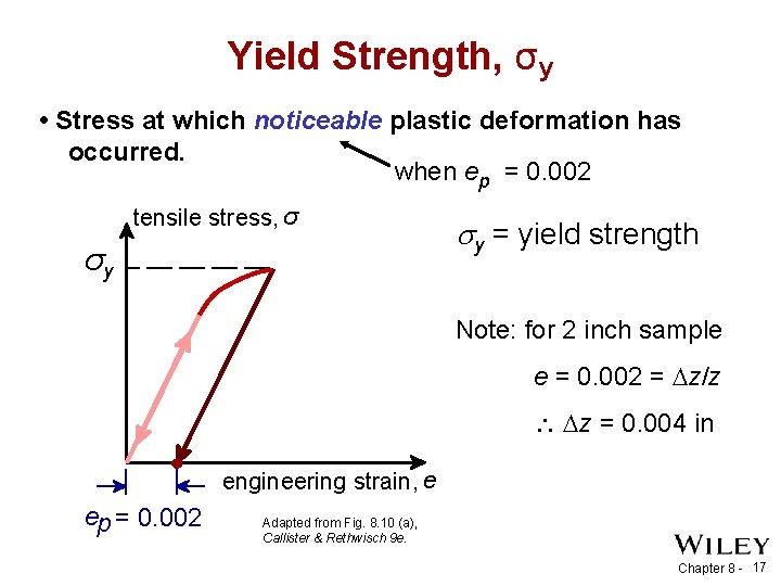
Yield Strength, σy • Stress at which noticeable plastic deformation has occurred. when ep = 0. 002 tensile stress, σ σy y = yield strength Note: for 2 inch sample e = 0. 002 = z/z z = 0. 004 in engineering strain, e ep = 0. 002 Adapted from Fig. 8. 10 (a), Callister & Rethwisch 9 e. Chapter 8 - 17
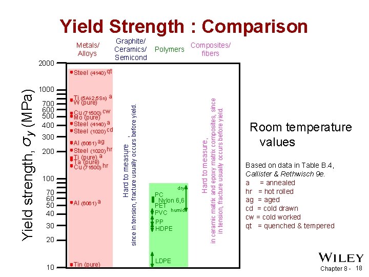
Yield Strength : Comparison Metals/ Alloys 2000 Graphite/ Ceramics/ Semicond Polymers Composites/ fibers 200 Al (6061) ag Steel (1020) hr Ti (pure) a Ta (pure) Cu (71500) hr 100 70 60 50 40 Al (6061) a 30 20 10 Tin (pure) ¨ dry PC Nylon 6, 6 PET PVC humid PP HDPE Hard to measure, 300 in ceramic matrix and epoxy matrix composites, since in tension, fracture usually occurs before yield. 700 600 500 400 Ti (5 Al-2. 5 Sn) a W (pure) Cu (71500) cw Mo (pure) Steel (4140) a Steel (1020) cd since in tension, fracture usually occurs before yield. 1000 Hard to measure , Yield strength, σ y (MPa) Steel (4140) qt Room temperature values Based on data in Table B. 4, Callister & Rethwisch 9 e. a = annealed hr = hot rolled ag = aged cd = cold drawn cw = cold worked qt = quenched & tempered LDPE Chapter 8 - 18
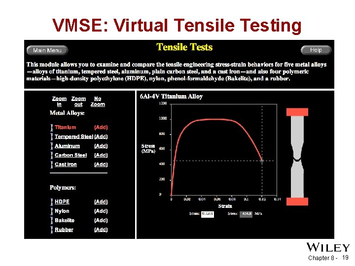
VMSE: Virtual Tensile Testing Chapter 8 - 19
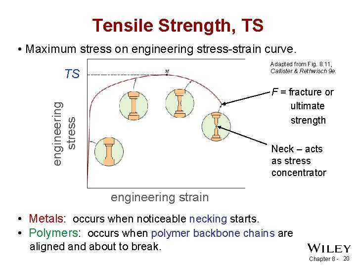
Tensile Strength, TS • Maximum stress on engineering stress-strain curve. Adapted from Fig. 8. 11, Callister & Rethwisch 9 e. TS F = fracture or ultimate strength engineering stress y Typical response of a metal Neck – acts as stress concentrator strain engineering strain • Metals: occurs when noticeable necking starts. • Polymers: occurs when polymer backbone chains are aligned and about to break. Chapter 8 - 20
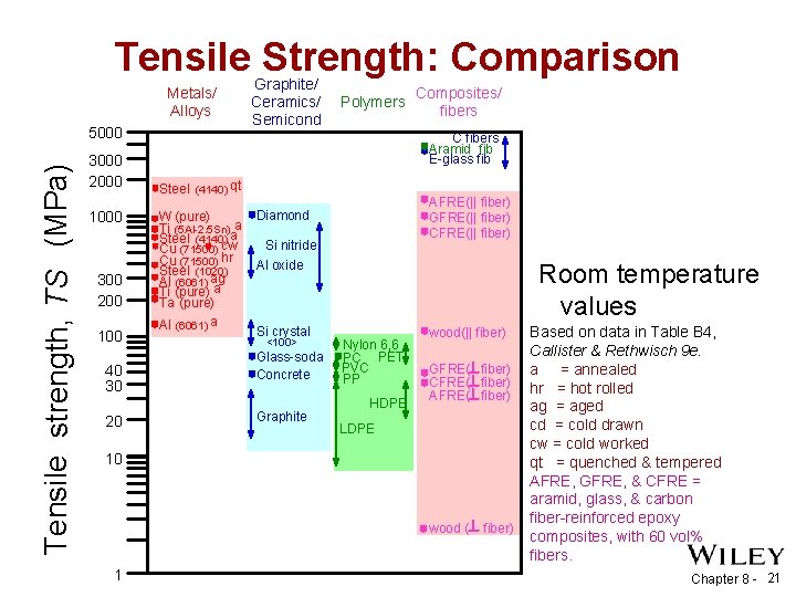
Tensile Strength: Comparison Metals/ Alloys Tensile strength, TS (MPa) 5000 3000 2000 1000 300 200 100 40 30 20 Graphite/ Ceramics/ Semicond Polymers Composites/ fibers C fibers Aramid fib E-glass fib Steel (4140) qt W (pure) Ti (5 Al-2. 5 Sn)aa Steel (4140)cw Cu (71500) hr Steel (1020) Al (6061) ag Ti (pure) a Ta (pure) Al (6061) a AFRE(|| fiber) GFRE(|| fiber) CFRE(|| fiber) Diamond Si nitride Al oxide Si crystal <100> Glass-soda Concrete Graphite Room temperature values Nylon 6, 6 PC PET PVC PP HDPE wood(|| fiber) GFRE( fiber) CFRE( fiber) AFRE( fiber) LDPE 10 wood ( 1 fiber) Based on data in Table B 4, Callister & Rethwisch 9 e. a = annealed hr = hot rolled ag = aged cd = cold drawn cw = cold worked qt = quenched & tempered AFRE, GFRE, & CFRE = aramid, glass, & carbon fiber-reinforced epoxy composites, with 60 vol% fibers. Chapter 8 - 21
Ductility • Plastic tensile strain at failure: Engineering tensile stress, σ Lf - Lo x 100 %EL = Lo smaller %EL larger %EL Lo Ao Af Lf Adapted from Fig. 8. 13, Callister & Rethwisch 9 e. Engineering tensile strain, e • Another ductility measure: %RA = Ao - A f x 100 Ao Chapter 8 - 22
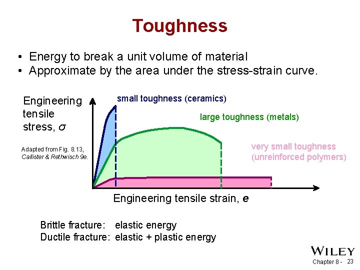
Toughness • Energy to break a unit volume of material • Approximate by the area under the stress-strain curve. Engineering tensile stress, σ small toughness (ceramics) large toughness (metals) very small toughness (unreinforced polymers) Adapted from Fig. 8. 13, Callister & Rethwisch 9 e. Engineering tensile strain, e Brittle fracture: elastic energy Ductile fracture: elastic + plastic energy Chapter 8 - 23
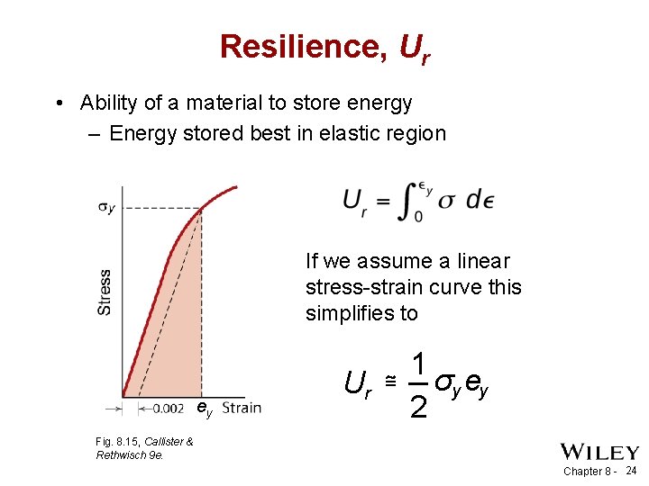
Resilience, Ur • Ability of a material to store energy – Energy stored best in elastic region If we assume a linear stress-strain curve this simplifies to ey 1 Ur ≅ σy ey 2 Fig. 8. 15, Callister & Rethwisch 9 e. Chapter 8 - 24
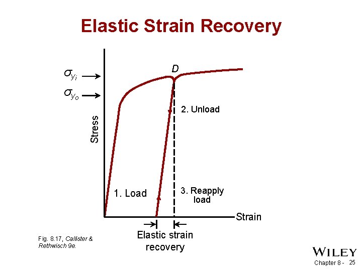
Elastic Strain Recovery D σ yi σ yo Stress 2. Unload 1. Load 3. Reapply load Strain Fig. 8. 17, Callister & Rethwisch 9 e. Elastic strain recovery Chapter 8 - 25
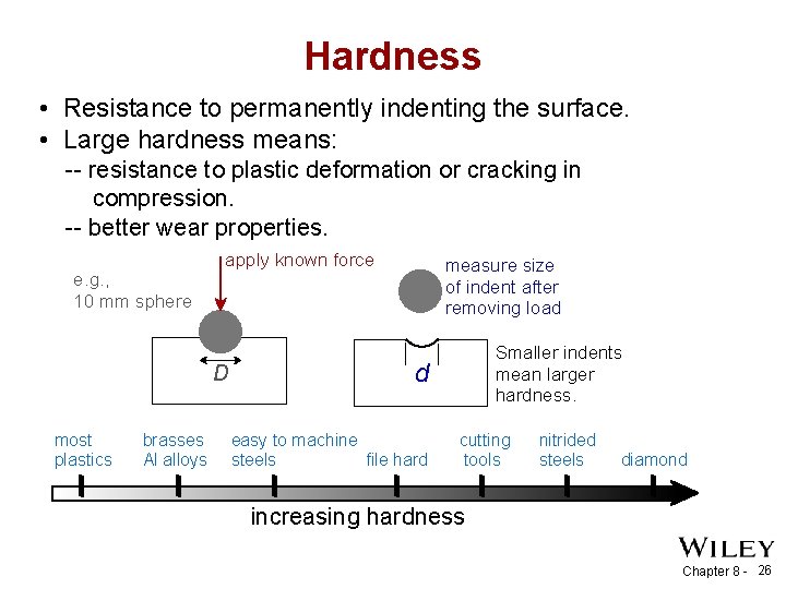
Hardness • Resistance to permanently indenting the surface. • Large hardness means: -- resistance to plastic deformation or cracking in compression. -- better wear properties. e. g. , 10 mm sphere apply known force D most plastics brasses Al alloys measure size of indent after removing load Smaller indents mean larger hardness. d easy to machine steels file hard cutting tools nitrided steels diamond increasing hardness Chapter 8 - 26
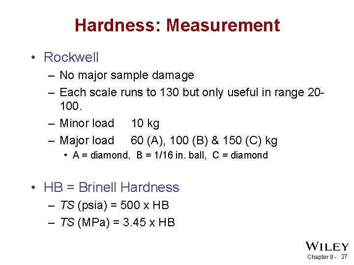
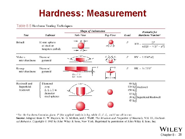
Hardness: Measurement • Rockwell – No major sample damage – Each scale runs to 130 but only useful in range 20100. – Minor load 10 kg – Major load 60 (A), 100 (B) & 150 (C) kg • A = diamond, B = 1/16 in. ball, C = diamond • HB = Brinell Hardness – TS (psia) = 500 x HB – TS (MPa) = 3. 45 x HB Chapter 8 - 27
Hardness: Measurement Table 8. 5 Chapter 8 - 28
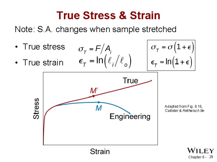
True Stress & Strain Note: S. A. changes when sample stretched • True stress • True strain Adapted from Fig. 8. 16, Callister & Rethwisch 9 e. Chapter 8 - 29
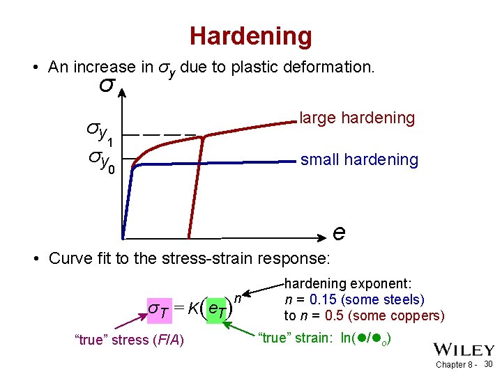
Hardening • An increase in σy due to plastic deformation. σ large hardening σy 1 σy small hardening 0 e • Curve fit to the stress-strain response: ( ) σ T = K e. T “true” stress (F/A) n hardening exponent: n = 0. 15 (some steels) to n = 0. 5 (some coppers) “true” strain: ln(l/lo) Chapter 8 - 30
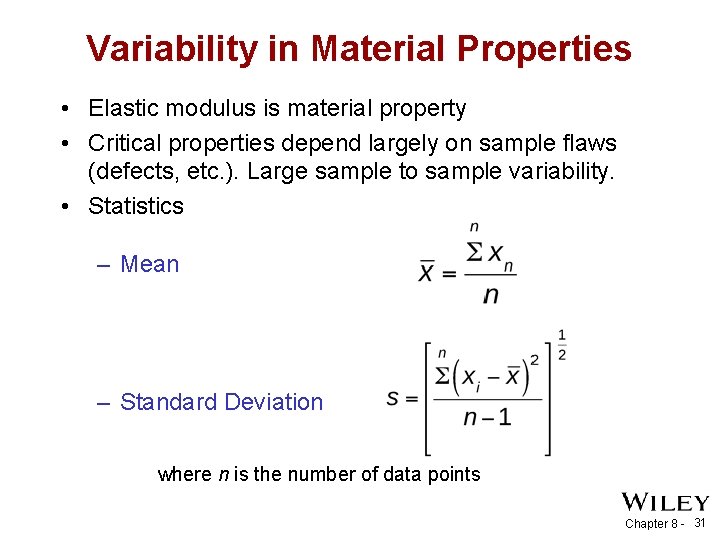
Variability in Material Properties • Elastic modulus is material property • Critical properties depend largely on sample flaws (defects, etc. ). Large sample to sample variability. • Statistics – Mean – Standard Deviation where n is the number of data points Chapter 8 - 31
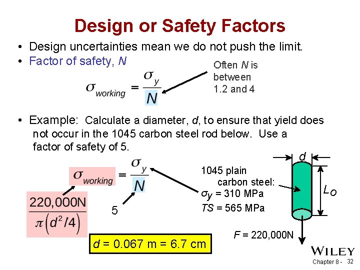
Design or Safety Factors • Design uncertainties mean we do not push the limit. • Factor of safety, N Often N is between 1. 2 and 4 • Example: Calculate a diameter, d, to ensure that yield does not occur in the 1045 carbon steel rod below. Use a factor of safety of 5. 5 1045 plain carbon steel: σy = 310 MPa TS = 565 MPa d = 0. 067 m = 6. 7 cm d Lo F = 220, 000 N Chapter 8 - 32
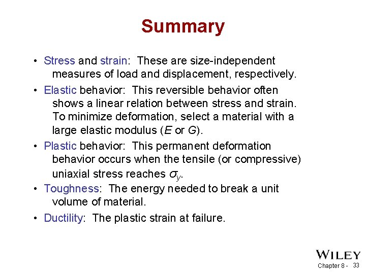
Summary • Stress and strain: These are size-independent measures of load and displacement, respectively. • Elastic behavior: This reversible behavior often shows a linear relation between stress and strain. To minimize deformation, select a material with a large elastic modulus (E or G). • Plastic behavior: This permanent deformation behavior occurs when the tensile (or compressive) uniaxial stress reaches σy. • Toughness: The energy needed to break a unit volume of material. • Ductility: The plastic strain at failure. Chapter 8 - 33
ANNOUNCEMENTS Reading: Core Problems: Self-help Problems: Chapter 8 - 34