CHAPTER 7 SUBSTATION AUXILIARY POWER SUPPLIES AND BUILDING

CHAPTER 7 SUBSTATION AUXILIARY POWER SUPPLIES AND BUILDING SERVICES

INTRODUCTION �AC power is required for : �Substation building small power �Lighting �Heating and Ventilation �Switchgear operating mechanisms �Anti condensation heaters �Motors

INTRODUCTION �DC power is used to feed essential services such as : �Circuit breaker trip coils and associated relays �Supervisory control and data acquisition (SCADA) �Communications equipment.

AC Auxiliary Systems 1. Typical Loads Supplied • Substation ac auxiliary systems are typically used to supply loads such as : • Transformer cooling, oil pumps and load tap • • • changers Circuit breaker air compressors and charging motors Outdoor device heaters Outdoor lighting and receptacles Control house Motor operated disconnecting switches
 Demand Load • Tabulate the connected k.")
AC Auxiliary Systems 2. Design Requirements a) Demand Load • Tabulate the connected k. VA of all substation ac loads and apply a demand factor to each • Demand k. VA is used to size the auxiliary transformers • Load diversity and load factor need not be considered in this case. • In auxiliary transformer sizing, examine the substation growth rate. • If expansion is planned in the near future, consider the estimated demand load of the expansion in the transformer size • If expansion is in the far future, it may be economically advantageous to plan for the addition of a transformers at expansion time
 Number of Primary Feeds �In small distribution substations one auxiliary")
AC Auxiliary Systems b) Number of Primary Feeds �In small distribution substations one auxiliary transformer is usually sufficient. �As substation size increase, customer load criticality increases �A decision has to be made as to redundancy of substation auxiliary services in light of economics and customer requirements. �Large transmission substation, servicing large load blocks and distribution stations, should have dual feeders serving two separate auxiliary transformers.
 Overhead or underground entry • The auxiliary source could be")
AC Auxiliary Systems c) Overhead or underground entry • The auxiliary source could be either overhead or underground distribution lines. • When under grounding within the substation property, direct buried conduit is recommended. • A spare, capped, conduit should be installed to minimize down time if a cable failure occurs. • The faulted cable can always be removed after service restoration.
 Critical Loads • Critical load for each station should be")
AC Auxiliary Systems d) Critical Loads • Critical load for each station should be determined. • These loads should be served from a panel fed from the normal source and representing the minimum load for transfer to alternative supply. • Some low-voltage loads have to be maintained at all times for examples: 1. 2. 3. 4. 5. 6. Transformer cooling Power circuit breaker compressors and motors Security lighting Breaker control circuits Fire alarm circuit Electric heating

DC AUXILIARY SYSTEM Typical Loads Supplied �Substation dc auxiliary systems are typically used to supply loads consisting of the following: 1. Relaying, supervisory, alarm and control equipment 2. Emergency control house lighting 3. Circuit breaker trip and close circuits

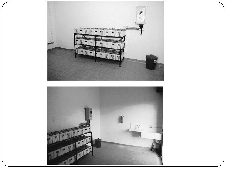
DC AUXILIARY SYSTEM Types of Cells �The type of cell for the particular application has to be selected. �There is no need for cell standardization on a power system. �Once a battery is installed for stationary service, it stays in place for up to 30 years. �Interchangeability on the system is unnecessary.

DC AUXILIARY SYSTEM �The types of secondary cells readily available today are : 1. Lead acid 2. Nickle cadmium 3. Lead calcium

DC AUXILIARY SYSTEM Determination Battery Size � Several basic factors govern the number of cells and rated capacity of the battery: 1. 2. 3. 4. 5. The maximum system voltage The minimum system voltage The duty cycle Correction factors Design margin � A battery string composed of a number of identical cells connected in series. � The voltage of the battery is the voltage of a cell multiplied by the number of cells in series.

DC AUXILIARY SYSTEM �The ampere hour capacity of a battery string is the same as the ampere hour capacity of a single cell. �Operating conditions can be charge the available of the battery, for example: 1. The available capacity decreases as its temperature decreases 2. The available capacity decreases as the discharge rate increases 3. The minimum specified cell voltage at any time during the battery discharge cycle limits the available capacity. 4. The charging method can affect the available

DC AUXILIARY SYSTEM Calculation of Number of Cells and Minimum Cell Voltage �The battery voltage is not allowed to exceed a given maximum system voltage. �The number of cells will be limited by the manufacturer’s recommended required for satisfactory charging. �Equation;

DC AUXILIARY SYSTEM �The minimum battery voltage equals the minimum system voltage plus any voltage drop between the battery terminals and the load. �The minimum battery voltage is then used to calculate the allowable minimum cell voltage. �Equation;

DC AUXILIARY SYSTEM Example 1 The dc system voltage limits are from 105 V to 140 V. The manufacturer recommends a cell voltage of 1. 47 V for satisfactory charging. The battery and charger must remain directly connected to the dc system at all times. Calculate the number of cell and the minimum cell voltage.

DC AUXILIARY SYSTEM Solution 1

DC AUXILIARY SYSTEM Ampere Hour Capacity �The capacity of battery system is specified in terms of amperes hours. �It is ampere hours which can be obtained from the charged batteries before reaching minimum voltage. �Ampere hours capacity is dependent on the magnitude of the discharge current.

DC AUXILIARY SYSTEM Charger Selection �Satisfactory battery life and service are more dependent on the design and specification of the charging equipment. �Shunt wound DC generators were used for charging bateries. �For substation service, bridge rectifiers are used. �The ampere capacity of the charger can be determined using:
 �L = continuous load (ampere)")
DC AUXILIARY SYSTEM �Where; �A = charge capacity (ampere) �L = continuous load (ampere) �C = discharge (ampere hour) �H = recharge time (hours) � 1. 1= constant

DC AUXILIARY SYSTEM Example 2 Calculate the charge capacity of the charger with an 8 hour recharge and continuous load, L is 5 Ampere if: DC components Ampere Duration (time) DC lights 3. 5 3 hours Communication 5 3 hours Breaker operations 100 1 minute Panel load 5 8 hours
 Discharge hours DC")
DC AUXILIARY SYSTEM Solution 2 DC Component Amper e Duration (time) Discharge hours DC lights 3. 5 3 hours 10. 5 AH Communicatio ns 5 3 hours 15 AH Breaker operations 100 1 minute 1. 7 AH Panel load 5 8 hours 40 AH Total discharge, 67. 2 AH C
- Slides: 23