
Chapter 6 Thermal oxidation and the SiSi O
- Slides: 22
Chapter 6 Thermal oxidation and the Si/Si. O 2 interface Si(s) + O 2(g) Si. O 2(s) 1. Si. O 2 properties and applications. 2. Thermal oxidation basics. 3. Manufacturing methods and equipment. 4. Measurement methods. 5. Deal-grove model (linear parabolic model). 6. Thin oxide growth, dependence on gas pressure and crystal orientation 7. Cl-containing gas, 2 D growth, substrate doping effect. 8. Interface charges, dopant redistribution. NE 343: Microfabrication and thin film technology Instructor: Bo Cui, ECE, University of Waterloo; http: //ece. uwaterloo. ca/~bcui/ Textbook: Silicon VLSI Technology by Plummer, Deal and Griffin 1
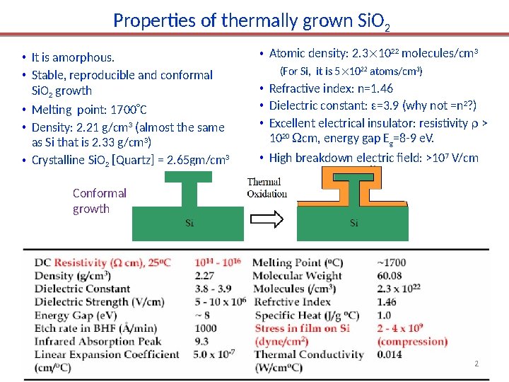
Properties of thermally grown Si. O 2 • It is amorphous. • Stable, reproducible and conformal Si. O 2 growth • Melting point: 1700 C • Density: 2. 21 g/cm 3 (almost the same as Si that is 2. 33 g/cm 3) • Crystalline Si. O 2 [Quartz] = 2. 65 gm/cm 3 • Atomic density: 2. 3 1022 molecules/cm 3 (For Si, it is 5 1022 atoms/cm 3) • Refractive index: n=1. 46 • Dielectric constant: =3. 9 (why not =n 2? ) • Excellent electrical insulator: resistivity > 1020 cm, energy gap Eg=8 -9 e. V. • High breakdown electric field: >107 V/cm Conformal growth 2
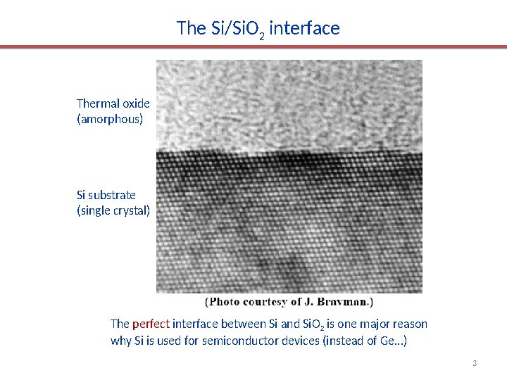
The Si/Si. O 2 interface Thermal oxide (amorphous) Si substrate (single crystal) The perfect interface between Si and Si. O 2 is one major reason why Si is used for semiconductor devices (instead of Ge…) 3
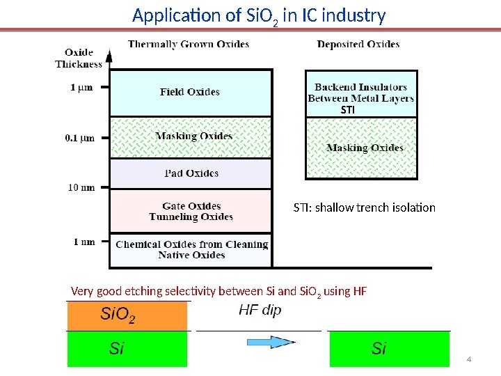
Application of Si. O 2 in IC industry STI: shallow trench isolation Very good etching selectivity between Si and Si. O 2 using HF 4
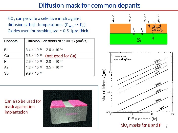
Diffusion mask for common dopants Si. O 2 can provide a selective mask against diffusion at high temperatures. (DSi. O 2 << Dsi) Oxides used for masking are 0. 5 -1μm thick. Can also be used for mask against ion implantation Mask thickness ( m) (not good for Ga) Diffusion time (hr) Si. O 2 masks for B and P 5
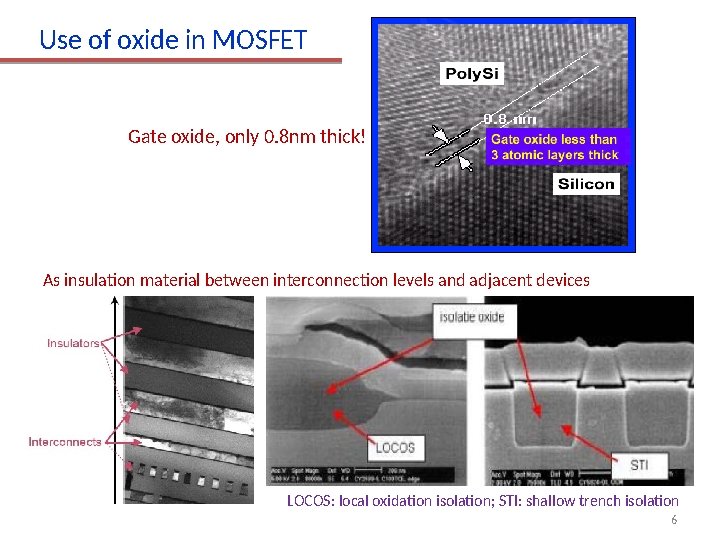
Use of oxide in MOSFET Gate oxide, only 0. 8 nm thick! As insulation material between interconnection levels and adjacent devices LOCOS: local oxidation isolation; STI: shallow trench isolation 6
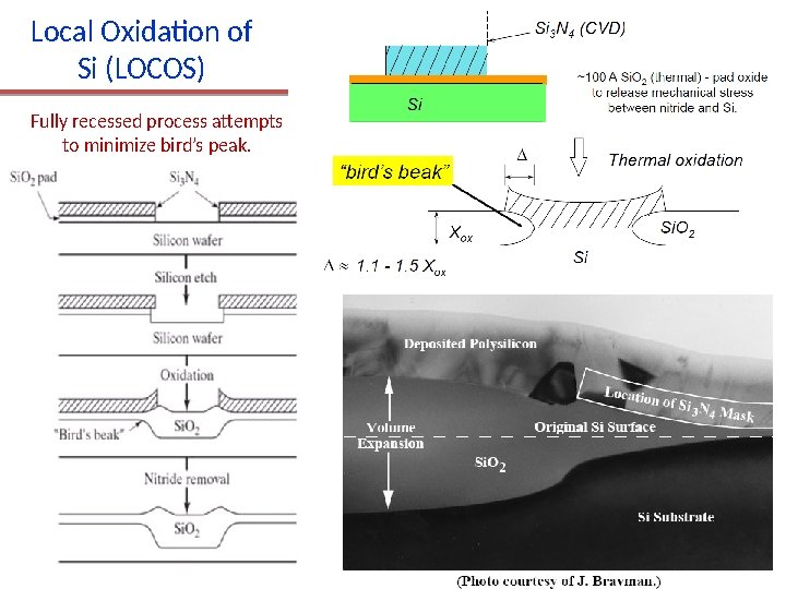
Local Oxidation of Si (LOCOS) Fully recessed process attempts to minimize bird’s peak. 7
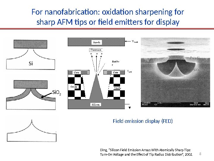
For nanofabrication: oxidation sharpening for sharp AFM tips or field emitters for display Si Si. O 2 Field emission display (FED) Ding, “Silicon Field Emission Arrays With Atomically Sharp Tips: Turn-On Voltage and the Effect of Tip Radius Distribution”, 2002. 8
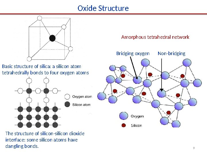
Oxide Structure Amorphous tetrahedral network 桥联氧oxygen 非桥联氧 Bridging Non-bridging Basic structure of silica: a silicon atom tetrahedrally bonds to four oxygen atoms The structure of silicon-silicon dioxide interface: some silicon atoms have dangling bonds. 9
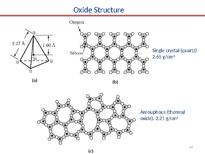
Oxide Structure Single crystal (quartz) 2. 65 g/cm 3 Amouphous (thermal oxide). 2. 21 g/cm 3 10
Chapter 6 Thermal oxidation and the Si/Si. O 2 interface 1. Si. O 2 properties and applications. 2. Thermal oxidation basics. 3. Manufacturing methods and equipment. 4. Measurement methods. 5. Deal-grove model (linear parabolic model). 6. Thin oxide growth, dependence on gas pressure and crystal orientation 7. Cl-containing gas, 2 D growth, substrate doping effect. 8. Interface charges, dopant redistribution. NE 343 Microfabrication and thin film technology Instructor: Bo Cui, ECE, University of Waterloo Textbook: Silicon VLSI Technology by Plummer, Deal and Griffin 11
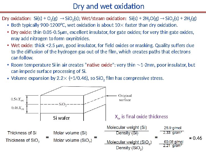
Dry and wet oxidation Dry oxidation: Si(s) + O 2(g) Si. O 2(s); Wet/steam oxidation: Si(s) + 2 H 2 O(g) Si. O 2(s) + 2 H 2(g) • Both typically 900 -1200°C, wet oxidation is about 10 faster than dry oxidation. • Dry oxide: thin 0. 05 -0. 5 m, excellent insulator, for gate oxides; for very thin gate oxides, may add nitrogen to form oxynitrides. • Wet oxide: thick <2. 5 m, good insulator, for field oxides or masking. Quality suffers due to the diffusion of the hydrogen gas out of the film, which creates paths that electrons can follow. • Room temperature Si in air creates “native oxide”: very thin 1 -2 nm, poor insulator, but can impede surface processing of Si. • Volume expansion by 2. 2 (=1/0. 46), so Si. O 2 film has compressive stress. Si wafer Xox is final oxide thickness = 0. 46
Chapter 6 Thermal oxidation and the Si/Si. O 2 interface 1. Si. O 2 properties and applications. 2. Thermal oxidation basics. 3. Manufacturing methods and equipment. 4. Measurement methods. 5. Deal-grove model (linear parabolic model). 6. Thin oxide growth, dependence on gas pressure and crystal orientation 7. Cl-containing gas, 2 D growth, substrate doping effect. 8. Interface charges, dopant redistribution. NE 343 Microfabrication and thin film technology Instructor: Bo Cui, ECE, University of Waterloo Textbook: Silicon VLSI Technology by Plummer, Deal and Griffin 13
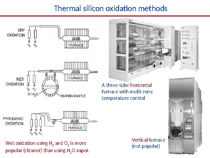
Thermal silicon oxidation methods A three-tube horizontal furnace with multi-zone temperature control Wet oxidation using H 2 and O 2 is more popular (cleaner) than using H 2 O vapor. Vertical furnace (not popular) 14
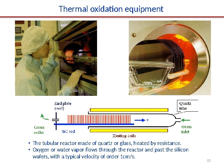
Thermal oxidation equipment • The tubular reactor made of quartz or glass, heated by resistance. • Oxygen or water vapor flows through the reactor and past the silicon wafers, with a typical velocity of order 1 cm/s. 15
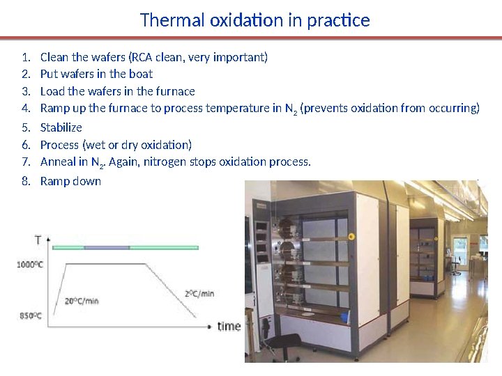
Thermal oxidation in practice 1. 2. 3. 4. Clean the wafers (RCA clean, very important) Put wafers in the boat Load the wafers in the furnace Ramp up the furnace to process temperature in N 2 (prevents oxidation from occurring) 5. Stabilize 6. Process (wet or dry oxidation) 7. Anneal in N 2. Again, nitrogen stops oxidation process. 8. Ramp down 1 -
Chapter 6 Thermal oxidation and the Si/Si. O 2 interface 1. Si. O 2 properties and applications. 2. Thermal oxidation basics. 3. Manufacturing methods and equipment. 4. Measurement methods (mechanical, optical, electrical). 5. Deal-grove model (linear parabolic model). 6. Thin oxide growth, dependence on gas pressure and crystal orientation 7. Cl-containing gas, 2 D growth, substrate doping effect. 8. Interface charges, dopant redistribution. NE 343 Microfabrication and thin film technology Instructor: Bo Cui, ECE, University of Waterloo Textbook: Silicon VLSI Technology by Plummer, Deal and Griffin 17
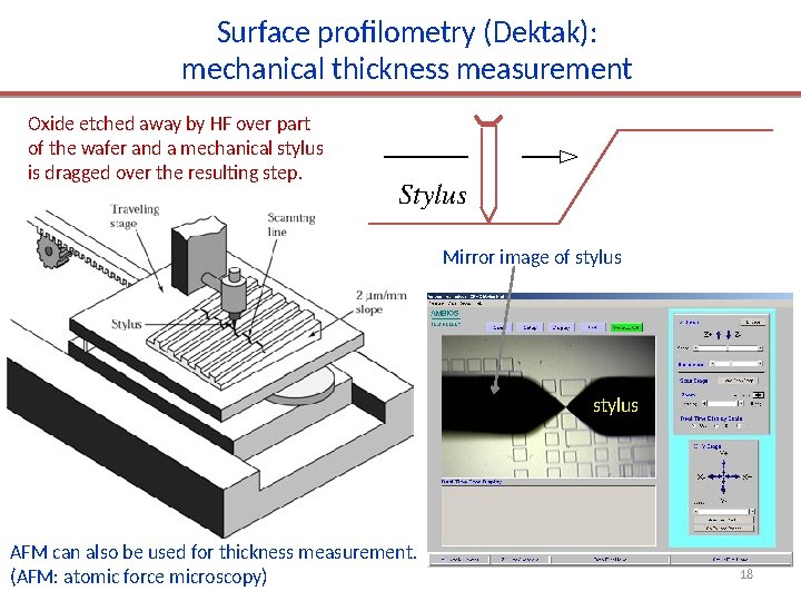
Surface profilometry (Dektak): mechanical thickness measurement Oxide etched away by HF over part of the wafer and a mechanical stylus is dragged over the resulting step. Stylus Mirror image of stylus AFM can also be used for thickness measurement. (AFM: atomic force microscopy) 18
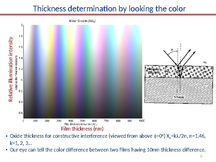
Relative illumination intensity Thickness determination by looking the color Film thickness (nm) • Oxide thickness for constructive interference (viewed from above =0 o) Xo=k /2 n, n=1. 46, k=1, 2, 3… • Our eye can tell the color difference between two films having 10 nm thickness difference. 1 -
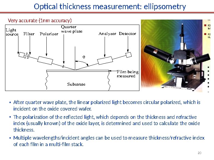
Optical thickness measurement: ellipsometry Very accurate (1 nm accuracy) Light source Filter Polarizer Quarter wave plate Analyzer Detector Film being measured Substrate • After quarter wave plate, the linear polarized light becomes circular polarized, which is incident on the oxide covered wafer. • The polarization of the reflected light, which depends on the thickness and refractive index (usually known) of the oxide layer, is determined and used to calculate the oxide thickness. • Multiple wavelengths/incident angles can be used to measure thickness/refractive index of each film in a multi-film stack. 20
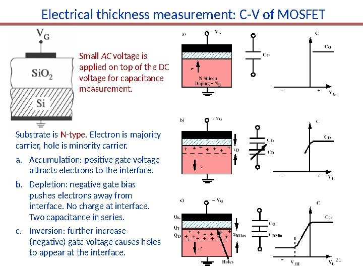
Electrical thickness measurement: C-V of MOSFET Small AC voltage is applied on top of the DC voltage for capacitance measurement. Substrate is N-type. Electron is majority carrier, hole is minority carrier. a. Accumulation: positive gate voltage attracts electrons to the interface. b. Depletion: negative gate bias pushes electrons away from interface. No charge at interface. Two capacitance in series. c. Inversion: further increase (negative) gate voltage causes holes to appear at the interface. 21
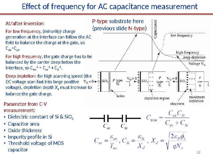
Effect of frequency for AC capacitance measurement At/after inversion: For low frequency, (minority) charge generation at the interface can follow the AC field to balance the charge at the gate, so Cinv=Cox. P-type substrate here (previous slide N-type) For high frequency, the gate charge has to be balanced by the carrier deep below the interface, so Cinv-1 = Cox-1 + CSi-1. Deep depletion: for high scanning speed (the DC voltage scan fast into large positive voltage), depletion depth Xd must increase to balance the gate charge. Parameter from C-V measurement: • Dielectric constant of Si & Si. O 2 • Capacitor area • Oxide thickness • Impurity profile in Si • Threshold voltage of MOS capacitor 22