Chapter 6 THE MECHANICAL ENERGY BALANCE THE MECHANICAL

Chapter 6 THE MECHANICAL ENERGY BALANCE

THE MECHANICAL ENERGY BALANCE Your objectives in studying this chapter are to be able to: 1. Explain what a reversible process is. 2. Identify a process as reversible or irreversible given a description of the process. 3. Define efficiency and apply the concept to calculate the work for an irreversible process. 4. Write down each of the terms in the steady-state mechanical energy balance for an open system, and understand the conditions under which the equation can be applied. 5. Apply the mechanical energy balance when appropriate to problems so that you can predict pressure drops, velocities, friction losses, and pump sizes.

THE MECHANICAL ENERGY BALANCE Ideal Reversible Processes The critical issue in designing and operating processes is not the conservation of energy, for example, applying the general energy balance. Energy in the system plus the surroundings (the universe) is always conserved. What is of concern is how energy can be converted from one form to another, and how efficiently the conversion can be made to take place. To characterize the interactions of energy within a system, and between the system and its surroundings, as the system moves from one state of equilibrium to another, scientists posit two types of processes: 1. Reversible: an idealized process (primarily hypothetical) in which changes occur because of an infinitesimal (differential) imbalance of temperature, pressure, and so on. 2. Irreversible: a process that is not reversible because it occurs with finite differences of temperature, pressure, and so on—most real processes.

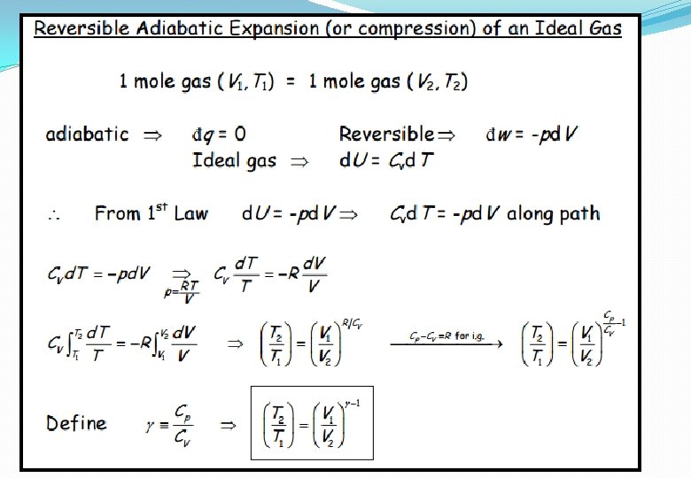
Ideal Reversible Processes As you might infer from the name, a reversible process is one in which the states of the system plus the surroundings can be reversed by a differential change in the driving potential (d. T, dp, etc. ). What we do is to characterize a process in words as “a controlled, very slow expansion, ” “frictionless, ” “elastic spring, ” and so on, so that it can be treated as reversible in your calculations. Examine Figure 14. 1.

Example 14. 1. Calculation of the Work Done during Evaporation of a Liquid How much work is done by 1 L of saturated liquid water when it evaporates from an open vessel into the atmosphere where the pressure is 100 k. Pa? Solution Example 14. 1 illustrates one real process that is essentially reversible. Steps 1– 4 The system is the water. The process is an open system. Does the water do work in evaporating? Certainly! It does work against the atmosphere by pushing it back. Furthermore, the process diagrammed in Figure E 14. 1, is a reversible one because the evaporation takes place at constant temperature (372. 78 K) and pressure, and presumably the conditions in the atmosphere immediately above the open portion of the vessel are in equilibrium with the water surface. The atmospheric pressure is 100 k. Pa. The basis will be 1 L of liquid water that vaporizes to a gas. The specific volume of the water vapor is 1. 694 m 3/kg H 2 O.
")
Step 5 Basis: 1 L of water (liquid)

Steps 8 and 9 The specific volume of the liquid water from the SI steam tables is 0. 001043 m 3/kg. The final volume of the water vapor is (the initial volume of H 2 O in the bag is zero and we will assume that there is enough water in the vessel so that the loss of liquid water to vapor is negligible). The specific volume of the liquid water is 0. 001043 m 3/kg. The specific volume of the water vapor is 1. 694 m 3/kg H 2 O.

Example 14. 2. Calculation of the Work in a Batch Process One kilogram mole of N 2 gas is in a horizontal cylinder at 1000 k. Pa and 20°C. A 6 cm 2 piston of 2 kg mass seals the cylinder and is fixed by a pin. The pin is released, and the N 2 volume is doubled, at which time the piston is stopped again. What is the work done by the gas in this process? Solution Steps 1– 4 Draw a picture. See Figure E 14. 2. From the ideal gas law you can compute the specific volume of the gas at the initial state: a. Is the process a flow or a non flow process? Since no material leaves or enters the cylinder, let us analyze the process as a non flow system. b. This process is definitely irreversible because of friction between the piston and the walls of the cylinder, turbulence in the gas, the large pressure drops, and so on. Choose the gas to be the system.

Step 5 We can use as a basis 2. 435 m 3 of N 2 at 1000 k. Pa and 20°C. Steps 6 and 7 We want to calculate the work done by the gas on the piston and the cylinder. As in Example 14. 1, the work cannot be calculated from the general energy balance because Q is unknown. Furthermore, because the process is irreversible, you cannot calculate the work done on the piston by – ∫ p d. V. Let us change our system to include the gas, the piston, and the cylinder. With this choice, the system expansion is still irreversible, but the pressure in the surroundings can be assumed to be atmospheric pressure and is constant. The work done in pushing back the atmosphere probably is done almost reversibly from the viewpoint of the surroundings, as assumed in Example 14. 1, and can be closely estimated by calculating the work done by the alternate system on the surroundings.

ΔV of the gas is 2 V 1 – V 1 = 2. 435 m 3, so that the volume change of the surroundings is – 2. 435 m 3. Basis: 2. 435 m 3 at 101. 3 k. Pa and 20°C (assumed) Then the work done on the surroundings is: From this we know that the work done by the alternate system is: Wsystem = – Wsurroundings = – 247 k. J

Efficiency If you look in the dictionary for the meaning of the word efficiency, you find “the ratio of the work done by an organism or machine to the amount of food or fuel consumed and to the energy expended. ” In engineering you will encounter a variety of more precise definitions of efficiency, some of which are listed in Table 14. 1. Numerous other specialized quantities termed efficiencies exist for hydroelectric plants; other power plants; automobile engines, transmissions, and drive trains; furnaces; combustion processes; and so on. Table 14. 2 lists some typical values of efficiencies of common equipment.

Table 14. 1. Various Process Efficiencies

Table 14. 2. Efficiencies of Energy Conversion

Example 14. 3. Efficiency of Power Generation by a Hydroelectric Plant A small hydroelectric plant puts out 20 MW when the level of water above the generators is 25 m and the water flow rate through the generators is 100 m 3/s. What is the overall efficiency of the plant? Solution The mass flow rate of the water (density 1000 kg/m 3) is: The potential energy change of the water per second is: The overall efficiency of the plant:

For a plant with multiple units you can compute the overall efficiency by multiplying together the efficiencies of the individual components. As an example, assume that the conversion of fuel in a power plant yields 88 k. J in the steam product per 100 k. J of available energy from the coal being burned. Also assume that the conversion of the energy in the steam to mechanical energy is 43% efficient, and the conversion of the mechanical to electrical energy is 97% efficient. The overall efficiency is (0. 88)(0. 43)(0. 97) = 0. 37, meaning that two-thirds of the initial energy is dissipated as heat to the environment. These definitions provide a good way to compare process performance for energy conservation (but not the only way).

Example 14. 4. Calculation of Plant Efficiency An analysis of energy usage takes place in all plants. Figure E 14. 4 illustrates a gas-fired boiler. The data calculated from measurements on the heater were (all in kilojoules per cubic meter at S. C. of fuel gas): Figure E 14. 4

Calculations from measurements gave values for sums of the other Qs of: Q 5 + Q 6 + Q 7 = 9092 Q 5 + Q 6 + Q 7 + Q 51 + Q 61 + Q 71 = 27, 119 Q 8 + Q 81 = 2352 From these heat transfer values, several efficiencies could be determined to evaluate plant performance: a. Gross efficiency b. Thermal efficiency c. Combustion efficiency

Calculations from measurements gave values for sums of the other Qs of: Q 5 + Q 6 + Q 7 = 9092 Q 5 + Q 6 + Q 7 + Q 51 + Q 61 + Q 71 = 27, 119 Q 8 + Q 81 = 2352 From these heat transfer values, several efficiencies could be determined to evaluate plant performance: a. Gross efficiency b. Thermal efficiency c. Combustion efficiency

The Mechanical Energy Balance Examine Figure 14. 2. What size pump should be selected to remove bio-waste from the collection tank? What pressure drop occurs between the collection tank drain and the pipeline to the treatment system? Figure 14. 2. Bio-waste collection system

The Mechanical Energy Balance In some processes, such as distillation columns or reactors, in which heat transfer and enthalpy changes are the important energy components in the energy balance, work, potential energy, and kinetic energy terms can be deemed to be zero or quite minor. However, in other processes, such as the compression of gases and pumping of liquids, work and the mechanical forms of energy are the important factors. For these processes, an energy balance, including solely the mechanical forms of energy, becomes a useful tool. Two categories of energy of different “quality” can be distinguished: a. The so-called mechanical forms of energy, such as kinetic energy, potential energy, and work, which are completely convertible by an ideal (reversible) engine from one form to another within the class. b. Other forms of energy, such as internal energy and heat, which are not so freely convertible.

A balance on mechanical energy can be written on a microscopic basis for an elemental volume by taking the scalar product of the local velocity and the equation of motion. After integration over the entire volume of the system, the steady-state mechanical energy balance for a system with mass interchange with the surroundings becomes, on a per unit mass basis: (14. 1)
 is called the Bernoulli equation for a reversible process in which")
Equation (14. 1) is called the Bernoulli equation for a reversible process in which Êν = 0. If the fluid is incompressible, and W = 0 The mechanical energy balance is best applied in fluid-flow calculations when the kinetic and potential energy terms and the work are of importance, and the friction losses can be evaluated from handbooks with the aid of friction factors or orifice coefficients. Let us now look at two typical applications of the steady-state mechanical energy balance.

Example 14. 5. Comparison of the Reversible Work for a Batch Process with That of a Flow Process Operating under the Same Conditions Five cubic feet of an ideal gas at 100°F are to be compressed adiabatically from 1 atm to 10 atm. The equation of state to use for the gas is p. V 1. 40 = constant. Two options exist for the compression: a. Compression in a horizontal cylinder with a piston b. Compression in a rotary compressor Calculate the reversible work required for the two alternate processes. Solution Process (a) This process is represented as a closed system similar to Figure 14. 1, but with the cylinder horizontal. The general energy balance reduces to: ΔE = ΔU = W

Steps 1– 4 You know the value of V 1 and have to calculate the value of V 2. The system is the gas. p. V 1. 40 = constant Step 5 Steps 6– 9 Basis: 5 ft 3 of gas at 100 o. F and 1 atm p. V 1. 40 = p 1 V 1 1. 40 = p 2 V 2 1. 40

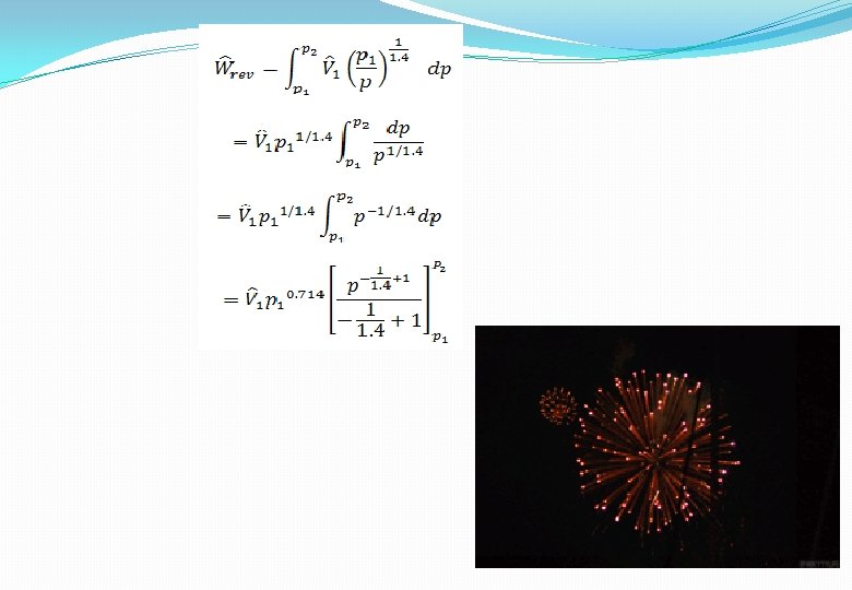
Process b You can represent this process as an open, steady-state system and apply the mechanical energy balance to solve for the reversible work: Figure E 14. 5

Step 1– 4 Figure E 14. 5 designates the system and data. The moles of gas are Step 5 Basis = 0. 0122 lb mol Steps 3, 6, 7, 8, and 9:

Example 14. 6. Application of the Mechanical Energy Balance to the Pumping of Water Calculate the work per minute required to pump 1 lb of water per minute from 100 psia and 80°F to 1000 psia and 100°F. The exit stream is 10 ft above the entrance stream. Solution This problem is typical of many fluid flow problems. Steps 1– 4 The system shown in Figure E 14. 6 is a steady-state process and the data have been placed in the figure. Steps 4, 6, and 7 The general mechanical energy balance is:
")
Subsequently, we will consider what to do if the process is (not reversible. ) Equation (a) reduces to: Step 5 Basis: 1 min of operation = 1 lb H 2 O Steps 6 and 8 From the steam tables, the specific volume of liquid water is 0. 01607 ft 3/lbm at 80°F and 0. 01613 ft 3/lbm at 100°F. For all practical purposes the water is incompressible, and the specific volume can be taken to be 0. 0161 ft 3/lbm. We have only one unknown in Equation (b): Ŵ. Step 9
- Slides: 30