Chapter 6 Registers I 0 Group of D


- Slides: 29

Chapter 6:

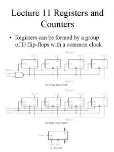
Registers I 0 « Group of D Flip-Flops D A 0 Q A 1 Q A 2 Q A 3 R « Synchronized (Single Clock) « Store Data Q I 1 D R I 2 D R I 3 CLK Reset D R 1 / 28

Registers CLK I 0 D Q A 0 Q A 1 Q A 2 Q A 3 R I 3 I 2 I 1 D I 1 R I 0 I 2 A 3 D A 2 R A 1 I 3 A 0 Note: Note New data has to go in with every clock CLK Reset D R 2 / 28

Registers with Parallel Load « Control Loading the Register with New Data D 7 D 6 D 5 D 4 D 3 D 2 D 1 D 0 R E G I S T E R LD Q 7 Q 6 Q 5 Q 4 Q 3 Q 2 Q 1 Q 0 LD 0 1 Q(t+1) Q(t) D 3 / 28

Registers with Parallel Load « Should we block the “Clock” to keep the “Data”? D 7 D 6 D 5 D 4 D 3 D 2 D 1 D 0 R E G I S T E R LD Q 7 Q 6 Q 5 Q 4 Q 3 Q 2 Q 1 Q 0 Delays the Clock Load CLK I 0 D Q A 0 I 1 D Q A 1 I 2 D Q A 2 I 3 D Q A 3 4 / 28

Registers with Parallel Load « Circulate the “old data” I 0 MUX Y I 1 S D Q A 0 I 1 I 0 MUX Y I 1 S D Q A 1 I 2 I 0 MUX Y I 1 S D Q A 2 I 3 I 0 MUX Y I 1 S D Q A 3 Load CLK 5 / 28

Shift Registers « 4 -Bit Shift Register Serial SI Input D Q D Q D SO Q Serial Output CLK 6 / 28

Shift Registers SI D Q Q 3 D Q Q 2 D Q Q 1 D Q Q 0 SO CLK SI Q 3 Q 2 Q 1 Q 0 7 / 28

Serial Transfer SI Clock Shift Control Shift Register A CLK SO SI Shift Register B CLK Clock Shift Control CLK 8 / 28

Serial Addition Shift Control CLK SI Shift Register A x y FA S C z Shift Register B Q D CLR Clear 9 / 28

Universal Shift Register « Parallel-in Parallel-out « Serial-in Serial-out « Serial-in Parallel-out « Parallel-in Serial-out D Q D Q 10 / 28

Universal Shift Register CLR CLK S 1 S 0 SI for SR Q 3 Q 2 Q 1 Q 0 Q Q D D Y S 1 S 0 MUX I 3 I 2 I 1 I 0 D 3 D 2 D 1 D 0 SI for SL 11 / 28

Universal Shift Register Q 3 Q 2 Q 1 Q 0 S 1 CLR S 0 USR SRin D 3 D 2 D 1 D 0 SLin Mode Control S 1 S 0 0 1 1 Register Operation No change Shift right Shift left Parallel load 12 / 28

Ripple Counters « Ripple ↔ Asynchronous Q 3 Q 2 Q T 1 Q 0 Q T 1 CLK CLR CLR CLR CLK Q 0 Q 1 Q 2 Q 3 13 / 28

Ripple Counters Q 3 Q 2 Q D Q 1 Q Q Q 0 D Q Q D CLK Q 0 Q 1 Q 2 Q 3 0 1 2 3 4 5 6 7 8 9 14 / 28

BCD Ripple Counter 0000 0001 0010 0011 0100 1001 1000 0111 0110 0101 Q 3 Q 2 Q 1 1 Q J Q K 1 Q 0 1 Q J Q K 1 CLK 15 / 28

Decades Counter Q 3 Q 2 Q 1 Q 0 BCD Counter 10’s Digit 100’s Digit Count (CLK) 16 / 28

Synchronous Binary Counter Q 3 To Next Stage Q 2 Q 1 Q 0 Enable Q J Q J Q K Q K CLK 17 / 28

Up-Down Binary Counter Q 3 Q 2 Q Q T Q 1 Q Q T Q 0 Q Q T Q CLK Up Down 18 / 28

BCD Counter 0 0000 0 1 0001 0 1 0010 0 1 0011 0 1 0100 1 1 1001 0 1 1000 0 1 0111 1 0110 0 0 1 0101 0 Q 3 Q 2 Q 1 Q 0 E 19 / 28

BCD Counter 0 0000 / 0 0 1 0 0001 / 0 1 0010 / 0 0 1 0011 / 0 0 1 0100 / 0 1 1 1001 / 1 0 1 1000 / 0 0 1 0111 / 0 1 0110 / 0 0 0 1 0101 / 0 0 Q 3 Q 2 Q 1 Q 0 y E 20 / 28

Binary Counter with Parallel Load CLR LD Count Q(t+1) 0 x x 0 1 0 0 Q(t) 1 0 1 Q(t)+1 1 1 x I I 3 Q 3 I 2 Q 2 I 1 Q 1 I 0 Q 0 LD Count CLR Usually Asynchronous Clear 21 / 28

BCD Counter Example LD Count 0 I 3 Q 3 A 3 0 I 2 Q 2 A 2 0 I 1 Q 1 A 1 0 I 0 Q 0 A 0 Count CLR 1 CLK 22 / 28

Ring Counter 0001 T 3 T 2 T 1 T 0 0010 0100 1000 CLK T 0 2 -to-4 Decoder T 1 T 2 2 -bit counter T 3 23 / 28

Johnson Counter 0000 0001 0011 0111 1000 1110 1111 Q 3 Q 1 Q 2 Q Q D Q 0 Q Q D Q CLK 24 / 28

Homework « Mano ● Chapter 6 ♦ 6 -2 ♦ 6 -3 ♦ 6 -4 ♦ 6 -13 ♦ 6 -14 ♦ 6 -16 ♦ 6 -18 25 / 28

Homework 6 -2 Include a synchronous clear input to the “Register with Parallel Load”. The modified register will have a parallel load capability and a synchronous clear capability. The register is cleared synchronously when the clock goes through a positive transition and the clear input is equal to 1. 6 -3 What is the difference between serial and parallel transfer? Explain how to convert serial data to parallel and parallel data to serial. What type of register is needed? 26 / 28

Homework 6 -4 The content of a 4 -bit register is initially 1101. The register is shifted six times to the right with the serial input being 101101. What is the content of the register after each shift? 6 -13 Show that a BCD ripple counter can be constructed using a 4 -bit binary ripple counter with asynchronous clear and a NAND gate that detects the occurrence of count 1010. 6 -14 How many flip-flop will be complemented in a 10 -bit binary ripple counter to reach the next count after the following count: (a) 100111 (b) 001111 (c) 11111 27 / 28

Homework 6 -16 The BCD ripple counter has four flip-flops and 16 states, of which only 10 are used. Analyze the circuit and determine the next state for each of the other six unused states. What will happen if a noise signal sends the circuit to one of the unused states? 6 -18 What operation is performed in the up-down counter when both the up and down inputs are enabled? Modify the circuit so that when both inputs are equal to 1, the counter does not change state, but remains in the same count. 28 / 28
 Register
 Chalumeau register clarinet
 Vocal registers
 Vocal fry
 Counters shift registers
 Registers and counters
 Flag register in 80386
 Model specific registers
 Nhmis monthly summary form
 Register in digital electronics
 Registers in computer
 Design of accumulator logic in computer architecture
 80386 features
 Common bus system for 4 registers
 8051 register bank
 Bris system
 Vga registers programming
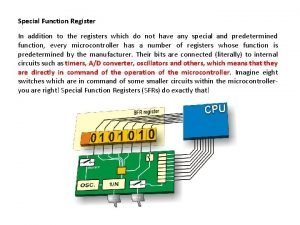
 What is special function register
 Counters shift registers
 Section 4-3 check registers
 Binary storage and registers
 Ax register in 8086
 8237 dma controller pin diagram
 Counters shift registers
 Hardware address protection with base and limit registers
 Marie registers
 Vector registers
 Ax bx cx dx
 Business registers interconnection system (bris)
 Registers
