Chapter 6 Inductance and Capacitance Inductors and Capacitors


 in your car fires")


 Current Pulse to Inductor • Apply current • Sketch current • When is")

![Using wolframalpha. com to differentiate • diff[ f(x), x ] takes derivative of some](https://slidetodoc.com/presentation_image_h2/430cfde05586ecbdc01eb138affad9fb/image-10.jpg "Using wolframalpha. com to differentiate • diff[ f(x), x ] takes derivative of some")


 Voltage Pulse to Inductor • Apply voltage • Sketch voltage • Find i(t)")
![Integrating with Wolfram Alpha • Basic indefinite integral: – Integrate[x^2, {x}] • Basic definite](https://slidetodoc.com/presentation_image_h2/430cfde05586ecbdc01eb138affad9fb/image-17.jpg "Integrating with Wolfram Alpha • Basic indefinite integral: – Integrate[x^2, {x}] • Basic definite")


")
")


- Slides: 34
Chapter 6 Inductance and Capacitance
Inductors and Capacitors • Energy Storage Components • Voltages and currents are related through calculus rather than ohm’s law – But KCL and KVL always apply at each instant • Resistors gave us static circuit behavior • Now we have dynamic currents and voltages changing over time • You may find a plotting calculator, or MATLAB to be very helpful in visualizing the variables
How they work • Inductor—Wire wrapped around magnetic core, current flow induces magnetic field, which dynamically induces voltage drop
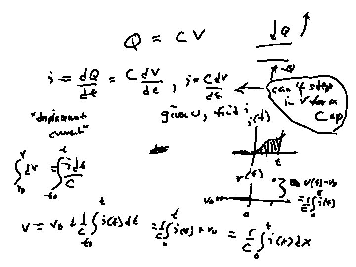
How they work • Capacitor—Two metal plates separated by a film, voltage applied causes “displaced current” to accumulate on plates
Energy is stored • Inductors store energy – Coil (inductor) in your car fires spark plugs at right moment • Capacitors store energy – Capacitor in your camera stores energy from batteries to fire flashbulb when picture is taken. • They can only release what has been stored – Can’t generate energy – They are passive components similar to resistors
R, L, C Comparison
6. 1 Inductors • A time-varying current source is applied across an inductor. Using the basic mathematical model, – What is the resulting voltage across the inductor vs time? – What is the power, energy, etc, vs time? – What if a time-varying voltage source is used instead? – To solve—determine which formula applies, then apply it.
1) Current Pulse to Inductor • Apply current • Sketch current • When is i at max? • determine voltage • sketch voltage
continue • when does V change polarity? • is there ever a step in V? in I?
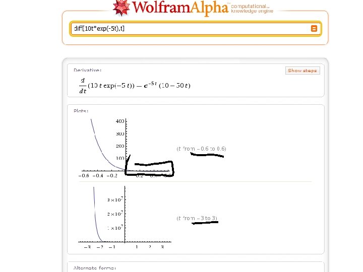
Using wolframalpha. com to differentiate • diff[ f(x), x ] takes derivative of some f(x) wrt x • diff[10 t*exp(-5 t), t] – Use * when needed to clarify – Use exp( ) to raise e to some exponent
If you don’t like the plot range, hover mouse over Lower Left plot corner
Copy paste back into WA with new limits
When you are happy, R-click plot, chose “copy”, then paste into Word Note: you must hover lower left corner to activate copy before copying
Derivative and Integral Relations
2) Voltage Pulse to Inductor • Apply voltage • Sketch voltage • Find i(t) • sketch i(t)
Integrating with Wolfram Alpha • Basic indefinite integral: – Integrate[x^2, {x}] • Basic definite integral – Integrate[x^2, {x, 0, 5}]
Integrating with Wolfram Alpha • Our integrals must be done using “dummy variable substitution” which is a definite integral from t 0 to t. In the last example, t 0=0 • In this last example – 0 + (1/0. 1)*Integrate[20 x*E^(-10 x), {x, 0, t}] =
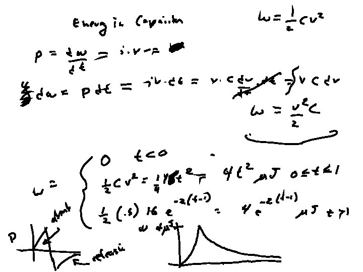
Power and Energy • p = i v = Li di/dt OR • p = dw/dt = Li di/dt • w = i 2 L/2
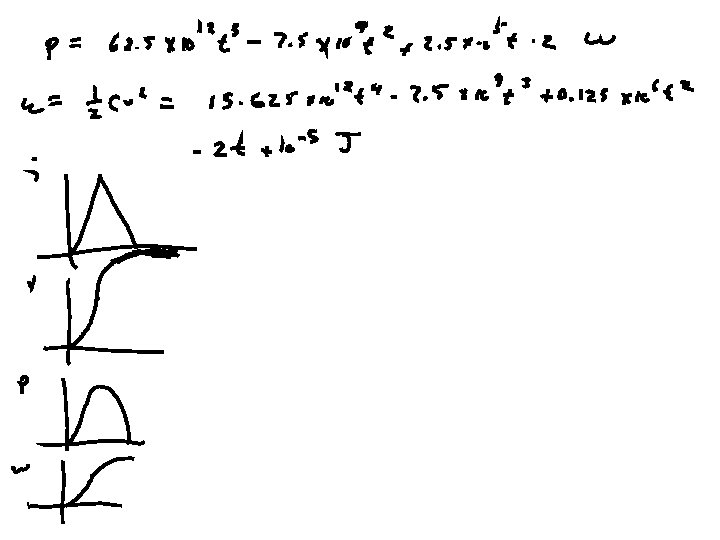
Find p and w for ex 1 • i= • v= • p= • w=
Sketch all four: i v p w
Find p and w for ex 2 • i= • v= • p= • w=
Sketch all four
Inductance • Inductance is the property of an electrical circuit causing voltage to be generated proportional to the rate of change in current in a circuit. This property also is called self inductance to discriminate it from mutual inductance, describing the voltage induced in one electrical circuit by the rate of change of the electric current in another circuit. • The quantitative definition of the self inductance L of an electrical circuit in SI units (webers per ampere, known as henries) is V = L di/dt, Unit: 1 H = 1 Wb/A
Capacitance • In a parallel plate capacitor, capacitance is directly proportional to the surface area of the conductor plates and inversely proportional to the separation distance between the plates. If the charges on the plates are +Q and −Q, and V gives the voltage between the plates, then the capacitance is given by • C = Q/V (or, Q = CV) Unit, 1 F = 1 C/V
Capacitor—Voltage Pulse (piecewise)
Capacitor—Current Pulse, (piecewise)
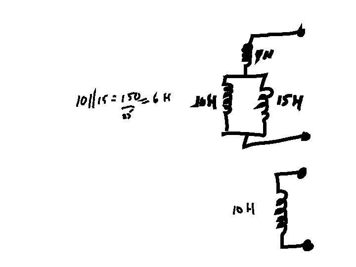
Series and Parallel Inductors • LIKE Resistors: Series ADD, Parallel, use formula
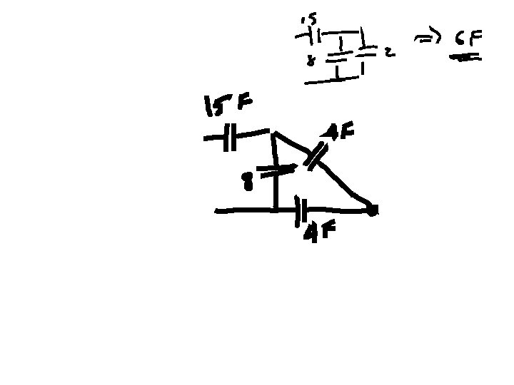
Series and Parallel Capacitors • UNLike Resistors: Parallel ADD, Series use formula