CHAPTER 6 GENERATION OF HIGH VOLTAGES CURRENTS 6


 � A high voltage is voltage being")


 the voltage ripple = 11. 67 k. V")
 the voltage drop and regulation")
 the max output voltage � (iv) the optimum number of stages")


- Slides: 50
CHAPTER 6 GENERATION OF HIGH VOLTAGES & CURRENTS 6. 0 Introduction 6. 1 Generation of High DC Voltages 6. 2 Generation of High AC Voltages 6. 3 Generation of Impulse Voltages 6. 4 Generation of Impulse Currents
6. 0 Introduction � Lightning discharges are the only known “natural” form of high voltage. � Other forms of high voltage are man-made or “synthetic” to fulfill specific goals. Three main purpose-oriented modes are: � The use of high voltage in electric power transmission to avoid excessive line currents which would render the transmission system uneconomical. � High voltage is utilized is based on the fact that bodies charged under high voltage develop an electrostatic force. Applications: cathode-ray tubes, particle accelerators, xerography, spray painting, and electrostatic precipitators. � High-voltage presence makes use of the ability of high voltage to initiate ionization in dielectric materials where energy is subsequently released in controlled quantities. Applications: e. g. , ignition in internal combustion engines, gas-discharge lamps, and ozone generation
Cont’… Definition of Voltage Levels (IEC 60038) � A high voltage is voltage being greater than 1000 V for ac and greater than 1200 V for dc. � Voltage class
Cont’… � In the fields of electrical engineering and applied physics, high voltages (d. c, a. c & impulse) are required for several applications. � For electron microscopes and x-ray units require high d. c voltage. � High a. c voltages are required for testing power apparatus (trasformers, cables, capacitors, circuit breakers, etc). � High impulse voltages are required for testing purposes to simulate overvoltages that occur in power system due to lightning or switching action. � For electrical engineers, the main concern of high voltages is for the insulation testing of various components in power systems.
6. 1 Generation of High DC Voltages �For the generation of D. C voltages of up to 100 k. V, electronic valve rectifiers are used and the output currents are about 100 m. A. �The rectifier valves require special construction since a high electrostatic field of several k. V/cm exists. �There are two methods of generating high D. C voltages: • through the process of rectification employing voltage multiplier circuits (Half-wave Rectifier Circuit, Full-wave Rectifier Circuit, Voltage Doubler Circuit & Cockroft-Walton Voltage Multiplier). • Electrostatic generators.
6. 1. 1 Half-wave Rectifier Circuit � The simplest circuit for generation of high direct voltage is the half wave rectifier shown in Fig. 6. 1(a) Fig. 6. 1 (a) Single Phase rectifier � Here RL is the load resistance and C the capacitance to smoothen the d. c. output voltage.
Cont’. . . � Assuming the ideal transformer and small internal resistance of the diode during conduction the capacitor C is charged to the maximum voltage Vmax during conduction of the diode D. � Assuming that there is no load connected, the d. c voltage across capacitance remains constant at Vmax whereas the supply voltage oscillates between ±Vmax � During negative half cycle the potential of point A becomes – Vmax
Cont’. . . � If the circuit is loaded, the output voltage does not remain constant at Vmax. � After point E (Fig. 6. 1 (c)), the supply voltage becomes less than the capacitor voltage, diode stops conducting. � The current now flows out of C to furnish the current i. L through the load. � While giving up this energy, the capacitor voltage also decreases at a rate depending on the time constant CR of the circuit and it reaches the point F corresponding to Vmin. � Beyond F, the supply voltage is greater than the capacitor voltage and hence the diode D starts conducting charging the capacitor C again to Vmax and also during this period it supplies current to the load also. Fig. 6. 1 (c) Output voltage with C
Cont’. . . � The single phase half-wave rectifier circuits have the following disadvantages: � (i) The size of the circuits is very large if high and pure d. c. output voltages are desired. � (ii) The h. t. transformer may get saturated if the amplitude of direct current is comparable with the nominal alternating current of the transformer.
6. 1. 2 Full-wave Rectifier Circuit �A full wave rectifier circuit is shown in Fig. 6. 2 � In the positive half cycle, the rectifier A conducts and charges the capacitor C. � In the negative half cycle the rectifier B conducts and charges the capacitor. � The sources transformer requires a centre tapped secondary with a rating of 2 V Fig 6. 2 Full wave rectifier
Cont’… � By using full-wave instead of half-wave circuit, the ripple voltage is halved, since the discharge period of half-wave is larger.
6. 1. 3 Voltage Doubler Circuit � High d. c. voltages can be generated by using : � � voltage doubler cascaded voltage multiplier circuits. One of the most popular doubler circuit due to Greinacher is shown in Fig. 6. 3 � Suppose B is more positive with respect to A and the diode D 1 conducts thus charging the capacitor C 1 to Vmax with polarity. � During the next half cycle terminal A of the capacitor C 1 rises to Vmax and hence terminal M attains a potential of 2 Vmax. � Thus, the capacitor C 2 is charged to 2 Vmax through D 2. � Normally the voltage across the load will be less than 2 Vmax depending upon the time constant of the circuit C 2 RL. � Fig. 6. 3 Voltage Doubler
6. 1. 4 Cockroft-Walton Voltage Multiplier � Fig. 6. 4 shows a multistage single phase cascade circuit of the Cockroft-Walton type. Fig. 6. 4 Cockroft-Walton Voltage Multiplier Circuit
Cont’… NO LOAD OPERATION � During the next half cycle when B becomes positive with respect to A, potential of M falls and, therefore, potential of N also falls becoming less than potential at M′ hence C 2 is charged through D 2. � Next half cycle A becomes more positive and potential of M and N rise thus charging C′ 2 through D′ 2. � Finally all the capacitors C′ 1, C′ 2, C′ 3, C 1, C 2, and C 3 are charged. � The voltage across the column of capacitors consisting of C 1, C 2, C 3, keeps on oscillating as the supply voltage alternates. � However, the voltage across the capacitances C′ 1, C′ 2, C′ 3, remains constant and is known as smoothening column. � The voltages at M′, N′, and O′ are 2 Vmax 4 Vmax and 6 Vmax. � The total output voltage is 2 n Vmax where n is the number of stages. � The equal stress of the elements (both capacitors and diodes) used is very helpful and promotes a modular design of such generators.
Cont’…
Cont’…
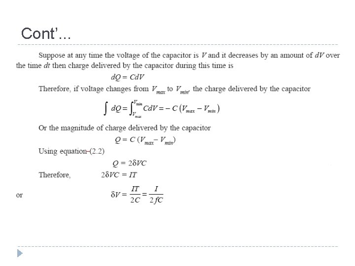
Cont’… GENERATOR LOADED � When the generator is loaded, the output voltage will never reach the value 2 n Vmax. � Also, the output wave will consist of ripples on the voltage. � Thus, we have to deal with two quantities, the voltage drop ΔV and the ripple δV. � For n-stage circuit, the total ripple will be,
Cont’… � Voltage drop, ΔV is the difference between theoretical no load voltage 2 n. Vmax and the onload voltage, � For large values of n (≥ 5) may be neglected, thus will be small and
Cont’… � Voltage regulation is the ratio between voltage drop and no load voltage, 2 n. Vmax � The optimum number of stages assuming a constant Vmax, I, f and C can be obtained � In general, it is more economical to use high frequency and smaller value of capacitance to reduce the ripples or the voltage drop rather than low frequency and high capacitance.
Problem 1 A ten stages Cockraft-Walton circuit has all capacitors of 0. 06 μF. The secondary voltage of the supply transformer is 100 k. V at a frequency of 150 Hz. If the load current is 1 m. A, determine � (i) the voltage ripple � (ii) the voltage drop and regulation � (iii) the max output voltage � (iv) the optimum number of stages
Solution � (i) the voltage ripple = 11. 67 k. V
� (ii) the voltage drop and regulation
� (iii) the max output voltage � (iv) the optimum number of stages
6. 2 Generation of High AC Voltages � Generation of high voltages and high currents are required for the purpose of testing various types of power system equipment. � Test transformers normally used for the purpose have low power rating but high voltage ratings. � These transformers are mainly used for short time tests on high voltage equipments. � For higher voltage requirement, a single unit construction becomes difficult and costly. � These drawbacks are overcome by series connection or cascading of the several identical units of transformers. � High AC voltages can be generated by either Test transformers or Resonant Circuits
6. 2. 1 Cascaded Transformers � For generating AC test voltages of less than a few hundred k. V, a single transformer can be used. � For voltages higher than 400 KV, it is desired to cascade two or more transformers. � Fig. 6. 6 shows a basic scheme for cascading three transformers. Fig. 6. 6 Basic 3 stage cascaded transformer
Con’t… � The primary of the first stage transformer is connected to a low voltage supply. � A voltage is available across the secondary of this transformer. � The tertiary winding (excitation winding) of first stage has the same number of turns as the primary winding, and feeds the primary of the second stage transformer. � The potential of the tertiary is fixed to the potential V of the secondary winding as shown in Fig. 6. 6. � The secondary winding of the second stage transformer is connected in series with the secondary winding of the first stage transformer, so that a voltage of 2 V is available between the ground and the terminal of secondary of the second stage transformer.
Con’t… � Similarly, the stage-III transformer is connected in series with the second stage transformer. � With this the output voltage between ground and the third stage transformer, secondary is 3 V. � The advantage of cascading the transformers is that the natural cooling is sufficient and the transformers are light and compact. � The main disadvantage of this scheme : � the lower stages of the primaries of the transformers are loaded more as compared with the upper stages � Bulky and heavy
6. 2. 2 Resonant Circuit � An alternative method that is more economical and sometimes technically superior is offered by resonant circuits Parallel resonant circuits involves the addition of parallel reactors either in the primary low-voltage circuit or the secondary high-voltage circuit. � The power factor can be greatly improved � A simplified diagram of the parallel resonant test system is given in Fig. 6. 7 � Fig. 6. 7 Parallel resonant test system
Cont’t… � An alternative system is the series resonance circuit. � By resonating the circuit through a series reactor L at the test frequency (50 Hz), harmonics are heavily attenuated. � A simplified diagram of the series resonance test system is given in Fig. 6. 8 Series resonant test system
Con’t… Advantages of Resonant Circuits � No high-power arcing and heavy current surges if the test object fails, as the resonance is heavily disturbed by the resulting short circuit � Cascading is also possible for higher voltage � Simple and compact test setup � Pure sinusoidal output waveforms � Less power requirements from the mains (5 to 10% of straight circuit requirements)
Problem 2 A 100 k. VA 250 V/200 k. V feed transformer has resistance and reactance of 1% and 5% respectively. This transformer is used to test a cable at 400 k. V at 50 Hz. The cable takes a charging current of 0. 5 A at 400 k. V. Determine the series inductance required. Assume 1% resistance of the inductor. Also determine input voltage to the transformer. Neglect dielectric loss of the cable.
6. 3 Generation of Impulse Voltages DEFINITIONS � An impulse voltage is a unidirectional voltage which, rises rapidly to a maximum value and falls more or less rapidly to zero. � The maximum value is called the peak value of the impulse. � A full impulse voltage is characterized by its peak value and its two time intervals, the wave front and wave tail time intervals. � The wave front time is specified as 1. 25 times (t 2 – t 1), where t 2 is the time for the wave to reach to its 90% of the peak value and t 1 is the time to reach 10% of the peak value. � Wave tail time is measured between the nominal starting point t 0 and the point on the wave tail where the voltage is 50% of the peak value i. e. wave tail time is expressed as (t 3 – t 0).
Con’t… Fig. 6. 9 Impulse Wave
Con’t… � The standardized lightning impulse waves are represented by the general equation � The tolerances allowed in the front and tail durations are ± 30% and ± 20% respectively � The tolerance allowed in the peak value is ± 3% � The standard lightning impulse wave has a front duration of 1. 2 μs and a wave tail duration of 50 μs, and is described as a 1. 2/50 μs wave. � The definition of the front and tail is as described in the IEC 60060 standard
Con’t… IMPULSE GENERATOR CIRCUITS � Two simplified but more practical forms of impulse generator circuits are shown in Fig. 6. 10 (a) and (b). Fig. 6. 10 Simplified equivalent circuit of an impulse generator
Con’t… � The two circuits are widely used and differ only in the position of the wave tail control resistance R 2. � When R 2 is on the load side of R 1 (Fig. a) the two resistances form a potential divider which reduces the output voltage � But when R 2 is on the generator side of R 1 (Fig. b) this particular loss of output voltage is absent.
Con’t… � The impulse capacitor C 1 is charged through a charging resistance to a d. c. voltage Vo � And then discharged by flashing over the switching gap with a pulse of suitable value. � The desired impulse voltage appears across the load capacitance C 2. � The value of the circuit elements determines the shape of the output impulse voltage.
Con’t… ANALYSIS OF CIRCUIT ‘a’ � The output voltage �Where;
Con’t… �The front wave time and the tail wave time can be determined approximately �The time for wave front �The time for wave tail
Con’t… ANALYSIS OF CIRCUIT ‘b’?
Con’t… Multistage Impulse Generators � The best way for generating voltage impulses of very high amplitudes using a DC source of a moderate output � A bank of capacitors are charged in parallel and then discharged in series, as originally proposed by Marx in 1923 � A typical modification of a Marx circuit is as shown � The gap spacing is chosen such that the breakdown voltage of the gaps F is slightly higher than the charging voltage V � All capacitors are charged to the voltage V
Con’t… Fig. 6. 11 Multistage Impulse Generators Circuit
Con’t… � When the impulse generator is to be discharged, the gaps F are made to spark over simultaneously by some external means � Thus all capacitors are connected in series and discharge through the wave-shaping resistors Rd‘ and Re‘ into the test object � Multistage impulse generators are usually specified by their total output voltage, the number of stages(n), and the stored energy
Con’t… � Single Stage Equivalent Circuit as shown;
6. 4 Generation of Impulse Currents Introduction � Generation of impulse currents of the order of several hundreds of kilo amperes finds applications in testing lightning arresters. � The waveshapes in common use are the double exponential
Con’t… � The impulse waveshape is defined according to IEC recommendation. � T 1 is the front duration and T 2 is the time to half peak. � According to IEC, the standard waves are 4/10 and 8/20 μs � To produce the standard waveform, a typical circuit as shown is normally used
Con’t… � Voltage V when the current im through in the circuit
Problem 3 Figure above shows the design circuit of an impulse current generator C represents a bank of capacitors connected in parallel which are charged form a DC source (140 k. V). R represents the dynamic resistance of the test object and L represent the air cored high current inductor. Calculate the impulse current if C is 25 n F. Given front time, tf = 8 μs, tail time, tt = 20 μs.
Thank You…