CHAPTER 6 FATIGUE TESTING By Noor Azira binti

CHAPTER 6 FATIGUE TESTING By; Noor Azira binti Mohd Noor

Introduction n n The name “fatigue” is based on the concept that a material becomes “tired” and fails at a stress level below the nominal strength of the material. Various structures and components in manufacturing operations such as tools, dies, gears, cams, shaft and sprig are subjected to rapidly fluctuating (cyclic or periodic) loads, in addition to static loads.

n Cyclic stress may be caused by fluctuating mechanical loads, such as ü on gear teeth or by thermal stresses ü On a cool die coming into repeated contact with hot workpieces. Under these condition the part fails at a stress level below that at which failure would occur under static loading. q This phenomena is known ad fatigue failure. q

Testing method n n Fatigue test method involved testing specimens under various states of stress usually in a combination of tension and compression in tension. The test is carried out at ü the various stress amplitude (S) ü The number of cycles (N) q It takes to cause total failure of the specimen or part is recorded.

n Stress amplitude is defined as the maximum stress in tension and compression to which the specimen is subjected.
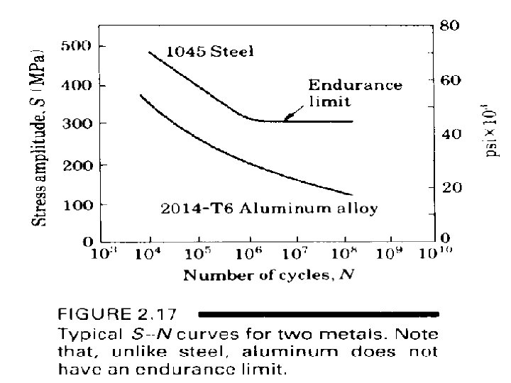

n n n S-N curves as shown above. These curves are based on complete reversal max tension max compression max tension other loading (eg bending) Endurance limit or fatigue limit – the max stress to which the material can be subjected without fatigue failure, regardless of the number of cycle.

n n Although many metal, especially steel have a definite endurance limit except aluminum alloy. The S-N curve for aluminum alloy continues its downward trend (refer S-N curve above). For metals exhibiting such behavior, the fatigue strength is specified at a certain no of cycle – 107 In this way the useful service life of the component can be specified.

n n The endurance limit for the metals can be approximately related to their ultimate tensile strength (refer graph below) For carbon steels, the endurance limit is usually 0. 4 – 0. 5 times the tensile strength, although particular values can vary.

Influences that can affect the endurance limit include: n n n n Surface Finish Temperature Stress Concentration Notch Sensitivity Size Environment Reliability

Preventing Fatigue Failure The most effective method of improving fatigue performance is improvements in design: n Eliminate or reduce stress raisers by streamlining the part n Avoid sharp surface tears resulting from punching, stamping, shearing, or other processes n Prevent the development of surface discontinuities during processing. n Reduce or eliminate tensile residual stresses caused by manufacturing. n Improve the details of fabrication and fastening procedures
- Slides: 11