Chapter 6 Design of Keys Splines and Pins


 Principles clearance")
 Types a. Plain flat keys 普通平键 (fixed joints) B Key with A Key")
")
")


Failure Modes: crush, wear, snip 2)Crushed Strength")
 Steps for Selecting Straight Keys • a. According to the diameter of shaft,")
 Double-Keys Arrangement")

 Greater carrying capacity; 2) Greater fatigue strength of a spline shaft; 3)")


- Slides: 19
Chapter 6 Design of Keys, Splines and Pins • • • Key terms: Keys Splines Keyway, keyseat Hub Crush Pin
6. 1 Key Joints • 1. Basic Concept A key is a fastening inserted into the keyway of two mating parts, it is used to transmit torque from a shaft to a hub or vice versa.
2. Types of Keys • Straight keys • Woodruff keys • Taper keys • Splines
3. Straight Key Joints • 1) Principles clearance
2) Types a. Plain flat keys 普通平键 (fixed joints) B Key with A Key with rounded ends square ends C Key with one square and one rounded end
b. guided keys (sliding joints)
c. feather key joints (sliding joints)
4. Woodruff Key Joints Greater depth of the key seat in the shaft.
5. Taper Key Joints Gib-head taper key
Tangent Double-taper Key Joints
6. Strength Calculation of Straight Key Joints 1)Failure Modes: crush, wear, snip 2)Crushed Strength Condition T——torque d——diameter of shaft h——thickness of the key l——working length of the key [ p]——allowable crush stress
3) Steps for Selecting Straight Keys • a. According to the diameter of shaft, get section size b h; • b. Select proper key length L in key length series; • c. Check the Strength Calculation (if necessary); h L b
4) Double-Keys Arrangement
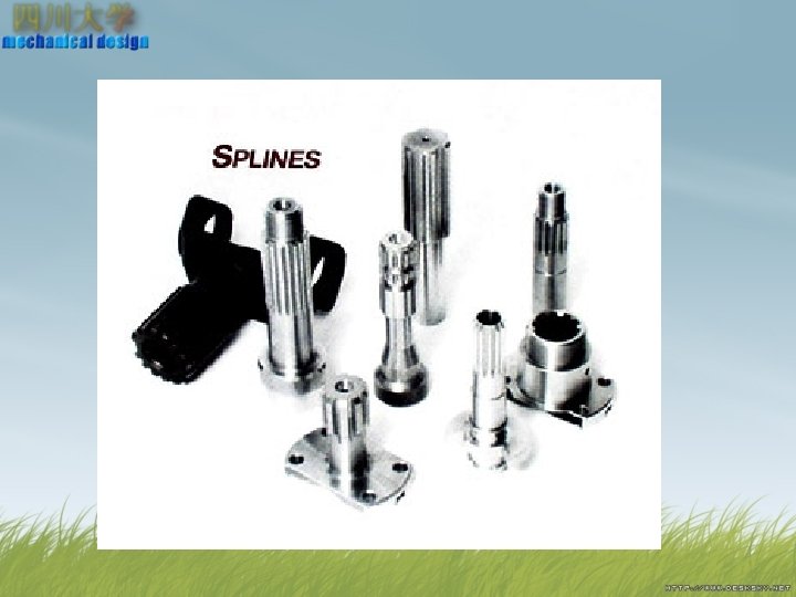
6. 2 Splines Joints • Splines can be dealt as multiple keys which are integral with the shaft. Splines are classified as: Parallel-sided splines Involute splines
Advantages: 1) Greater carrying capacity; 2) Greater fatigue strength of a spline shaft; 3) More accurately centered and guided. Disadvantages: Requirements for special equipments and tools, which increase the manufacturing costs.
6. 3 Pin Joints Cylindrical pin Taper pin safety pin Pin for joining
Key Standards
The end Thanks!