Chapter 51 Antilock Brake Traction Control and Stability

Chapter 51 Antilock Brake, Traction Control, and Stability Control Systems

Antilock Brakes • The ABS system pulses the brakes more rapidly than the driver can. • Pulsing the brakes prevents wheel lockup. • Preventing wheel lockup provides for more stable stopping. • Preventing wheel slip allows the wheels to turn as directed.

Pressure Modulation • If the wheels lock the vehicle will slide. • Pumping the brakes allows the driver to maintain control. • When the ABS pumps the brakes it is called pressure modulation. • The ABS can modulate brake pressure up to 15 times per second.

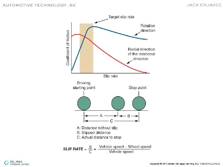
Slip Rate • Maneuverability is reduced when the front wheels are locked. • The ABS control module calculates slip rate based on wheel speed sensor (WSS) data. • 0% slip equals a wheel freely rolling. • 100% slip equals a locked wheel. • The ABS target rate is about 10 to 30% slip.

Pedal Feel • Different than a non-ABS equipped vehicle. • When the ABS activates, a small bump followed by rapid pedal pulsations. • The pedal may drop lower than normal under ABS braking.

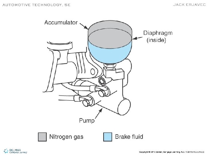
Hydraulic Components • Accumulator – Stores fluid to maintain high pressure and provide residual pressure for power-assist – Charged with nitrogen gas • Control Valve Assembly – Controls the release and application of brake system pressure to the wheel brake assemblies
 • Booster Pump – Provides pressurized hydraulic fluid for the ABS")
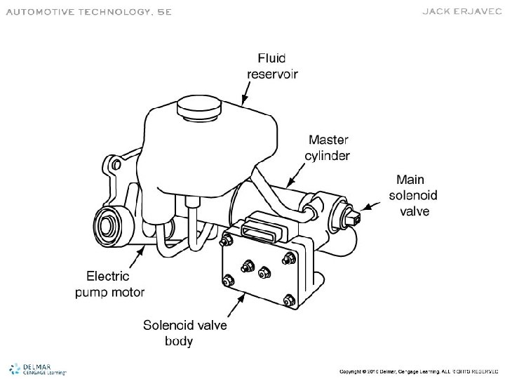
Hydraulic Components (cont’d) • Booster Pump – Provides pressurized hydraulic fluid for the ABS system – Controlled by the ABS control unit • Booster/Master Cylinder Assembly – Contains the valves and pistons used to modulate hydraulic pressure during ABS operation
 • Fluid Accumulator – Stores fluid that is removed from the")
Hydraulic Components (cont’d) • Fluid Accumulator – Stores fluid that is removed from the wheel circuits during the ABS cycle • Hydraulic Control Unit – Contains solenoid valves, fluid accumulators, pump, and electric motor in one unit
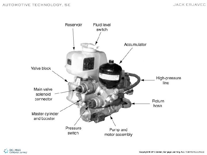
 • Modulator Unit – Controls the flow of fluid to the")
Hydraulic Components (cont’d) • Modulator Unit – Controls the flow of fluid to the individual wheel circuits • Hydraulic Valves – Control and direct hydraulic pressure • Solenoid valves • Main valve • Wheel circuit valves

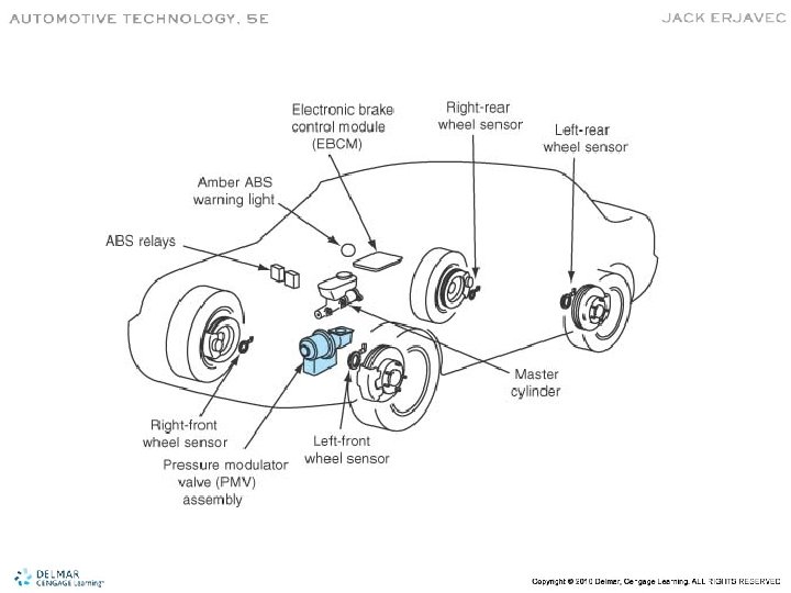
Electrical/Electronic Components • Control Module – Controls ABS operation and monitors the system • Brake Pedal Sensor – Signals the control module when the brake is applied • Data Link Connector (DLC) – Provides access to and/or control of vehicle information
 • Relays – Used to switch motors and solenoids • Toothed")
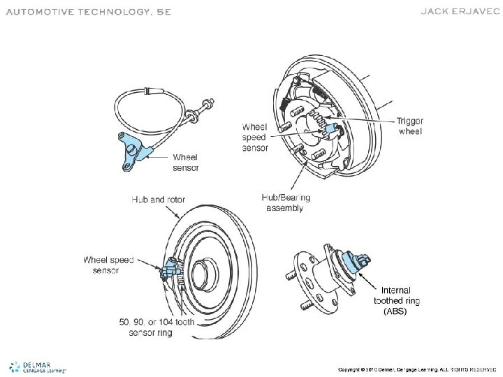
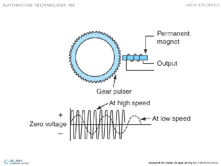
Electrical/Electronic Components (cont’d) • Relays – Used to switch motors and solenoids • Toothed Ring – Each tooth generates voltage in the WSS • Wheel Speed Sensors – Sends wheel speed information to the ABS module – Is usually comprised of a magnet and a coil of wire and produces an AC signal

Multiplexing • ABS it part of the CAN network. • Allows communication among modules.

Basic ABS Operation • Control unit process inputs and controls the operation of the isolation/dump valves.

ABS Types • Integral – Combines the master cylinder, power booster, and ABS hydraulic circuitry in one unit • Non-Integral – Uses a conventional power booster and master cylinder – The electrohydraulic control unit may be mounted to the master cylinder or remotely

Integral ABS

ABS System Channels • One-channel System – Only modulates both rear brakes at the same time • Three-channel System – Has individual circuits to each front wheel and one circuit to both rear wheels • Four-channel System – Controls each wheel separately

Typical Four-Wheel ABS System
 – No additional pressure is allowed to")
ABS Operating Modes • Pressure Hold (retaining) – No additional pressure is allowed to reach the brake • Pressure Release (decrease) – Pressure is released so the wheel can turn • Pressure Apply (increase) – Brake pressure is reapplied to the affected brake
 • ATC systems apply the brakes when a drive wheel")
Automatic Traction Control (ATC) • ATC systems apply the brakes when a drive wheel attempts to spin or lose traction. • ABS controls negative wheel slip. • ATC controls positive wheel slip. • ATC is most helpful on four-wheel and allwheel drive vehicles.

Engine Controls • More advanced ATC systems work at high speeds. • If wheel slip is detected, the PCM may reduce torque to the drive wheels by: – Retarding spark timing – Reducing or cutting of fuel injectors – Increasing EGR flow – Upshifting the transmission

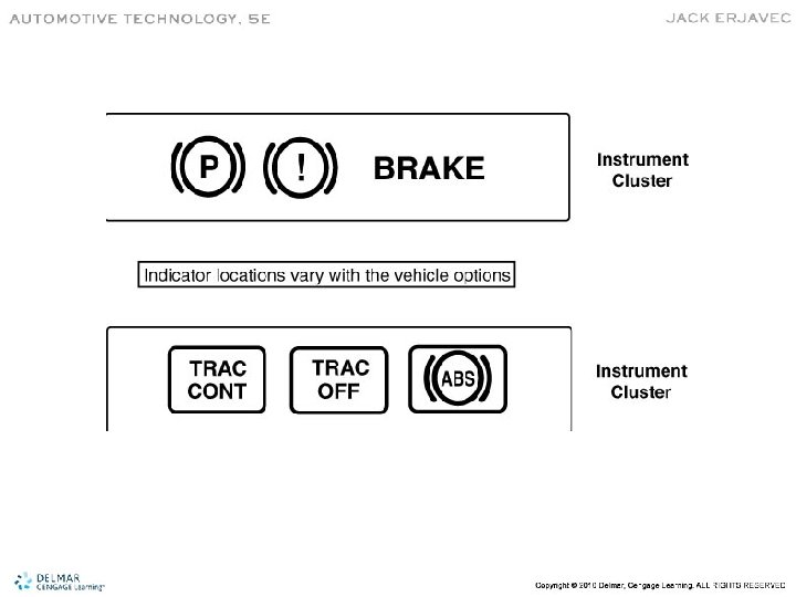
Driver Controls and Indicators • Most have two warning lights. – If an ABS disabling fault occurs, the ATC is also disabled • Some vehicles have an ATC cut-off switch.
 • Linked with the ABS •")
Automatic Stability Control or Electronic Stability Control (ESC) • Linked with the ABS • May be linked with the electronic suspension system. • Helps prevent skids, swerves, and rollovers by helping the driver maintain control.

Typical ESC System
 • The control unit monitors lateral acceleration, yaw rate, and brake pressure.")
ESC (cont’d) • The control unit monitors lateral acceleration, yaw rate, and brake pressure.

ABS Service • Most service is identical as with a conventional brake system. • Always refer to the recommended procedures before attempting to service brakes on an ABS-equipped vehicle. • Normal brake repairs are performed as usual.

Service Safety Precautions • Always use lines and hoses designed for ABS vehicles. • Never use silicone brake fluid in an ABS system. • Always follow the proper bleeding procedure. • Never open a bleeder screw with the system pressurized.
 • Never disconnect or reconnect electrical connectors with the ignition")
Service Safety Precautions (cont’d) • Never disconnect or reconnect electrical connectors with the ignition switch on. • Do not install electronic accessories near any control module. • Keep the wheel speed sensors clean. • Never use a hammer to install speed sensor toothed rings.

Relieving Accumulator Pressure • Accumulator pressure can be as high as 2, 800 psi (19, 300 k. Pa). • Before servicing, relieve system pressure. • A common method includes: – Turn the ignition off – Pump the brake pedal 25 to 50 times • Procedures vary – always refer to the service manual.

Prediagnostic Inspection • Observe the red brake and amber ABS lights • Check fluid level • Inspect hoses, lines, and fitting for leaks or damage • Inspect all brake components • Check for loose wheel bearings • Check outer CV joint alignment • Check tire tread depth • Check electrical connections for corrosion and damage • Inspect wheel sensors and wiring

Test Drive • Begin with brake pedal feel at a stop. • Accelerate to about 25 mph (32 km/h) and apply the brakes. – Note swerving or improperation • Test for unwanted low-speed ABS activation.

Self-Diagnostics • A malfunction will cause the control module to shut off the ABS system. • A self check is performed at each start-up. • Each system has specific diagnostic modes and procedures. • Always refer to the manufacturers service information.

Example of ABS Diagnosis

Wheel Speed Sensor Service • Inspect for chipped or crack pulser teeth. • Use a feeler gauge to measure the air gap. • Inspect for rust and metal buildup on the sensor. • PM generator sensor wiring is twisted pair and not servicable.

Inspect for rust and metal buildup Check for cracks and missing teeth

Brake System Bleeding • Always refer to the service manual before attempting to bleed the ABS system. • Example:
- Slides: 43