Chapter 5 Verilog 1 Chapter 5 Verilog n


![Testbench語法(cont. ) n A Example of Testbench. module four_bit_adder_tb; n reg [3: 0] x;](https://slidetodoc.com/presentation_image_h/f49b317d4fab8f770d3e0c620c36ac8b/image-19.jpg "Testbench語法(cont. ) n A Example of Testbench. module four_bit_adder_tb; n reg [3: 0] x;")
 n n n n Gate – level module tech")
 n n module tech 1(X, Y, Z, F); input")
 n n n Design Circuit Behavioral-level module tech 1(X,")
 注意顏色的對應,代表模組與模組的對應 n module testtech 1; // Inputs reg X; reg")
 輸入觸發(up counter) 輸入觸發(down counter) always #5 X=X+1; always #10 Y=Y+1;")
 輸入觸發(user define) 輸入觸發(random) initial begin #5 X=0; Y=0; Z=0; #5")

- Slides: 26
Chapter 5 Verilog硬體描述語言 1
Chapter 5 Verilog硬體描述語言 n n Verilog的行為描述語法 Verilog測試向量語法 2
Chapter 5 Verilog硬體描述語言 n n Verilog的行為描述語法 Verilog測試向量語法 3
6
10
13
Chapter 5 Verilog硬體描述語言 n n Verilog的行為描述語法 Verilog測試向量語法 16
Testbench架構 Testbench `timescale 1 ns / 1 ps//前面的1 ns代表程式中最小的時間單位後面的1 ps代表運算的精準度 module totaltestt; // testbench命名 // Inputs //將Input設為 reg [3: 0] mesg; //將Input設為 reg clk; //將Input設為 reg rst; //將Input設為 reg // Outputs //Output設為wire [6: 0] omesg; //Output設為wire // Instantiate the Unit Under Test (UUT) testmodule uut //將要測試的HDL名字寫進來,uut只是一個隨便的命名 ( //將HDL的port和testbench的port做連接 . mesg(mesg), . clk(clk), . rst(rst), . omesg(omesg) ); initial begin //initial為只執行一次的訊號 // Initialize Inputs mesg = 0; //初始資料一開始為 0 clk = 0; //clock一開始為 0 rst = 0; //reset一開始為 0 #1000 $finish; // 執行1000 ns後結束 end // Add stimulus here // 觸發訊號設定 Initial //initial為只執行一次的訊號 begin #5 rst = 1; // 5 ns後reset設定為 1,重置結束 end always#10 clk=~clk; //always為重複性迴圈,只要達成條件就執行,本條件是每 10 ns就把clk訊號反向 always#20 mesg = mesg+1; //每 20 ns就把輸入訊號+1 endmodule Testbench module Switchlevel Gate level Dataflowlevel Behaviorallevel Call Design Circuit Module endmodule 17
Testbench語法 n All of the Verilog language can be used. n Usual Syntax n n n #number:number=time unit of delay. initial:just execution at a time. always:still execution until break. $random[(seed)]: a 32 -bit random number of signed integer. $finish:finish the simulation 18
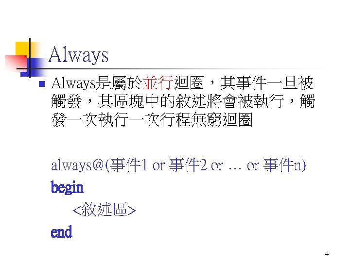
Testbench語法(cont. ) n A Example of Testbench. module four_bit_adder_tb; n reg [3: 0] x; n reg [3: 0] y; n reg c_in; n wire [3: 0] sum; n wire c_out; n fout_bit_adder uut (. x(x), . y(y), . c_in(c_in), . sum(sum), . c_out(c_out)); n initial begin n x = 0; n y = 0; n c_in = 0; n end n always begin n #100 //delay 100 unit n x = $random % 16; //generate 4 -bit random number(0~15) generate input by n y = $random % 16; //generate 4 -bit random number(0~15) each delay time n c_in = $random % 2; //generate 1 -bit random number(0~1) n end n initial #2000 $finish; Set total time of simulation n endmodule n input output Instantiate the Unit Under Test (UUT) set initial value 19
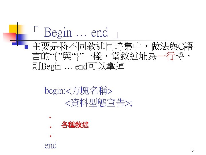
Ex. Design Circuit Module (1/3) n n n n Gate – level module tech 1(X, Y, Z, F); input X; input Y; input Z; output F; wire F 1; wire F 2; wire Y 1; Design Circuit module Switchlevel Gate level Dataflowlevel Behaviorallevel endmodule not (Y 1, Y); and (F 1, X, Y 1); or (F 2, Y, Z); or (F, F 1, F 2); endmodule 20
Ex. Design Circuit Module (2/3) n n module tech 1(X, Y, Z, F); input X; input Y; input Z; output F; wire F; assign F=(X&~Y)|(Y|Z); n endmodule n n n Design Circuit Dataflow-level module Switchlevel Gate level Dataflowlevel Behaviorallevel endmodule 21
Ex. Design Circuit Module (3/3) n n n Design Circuit Behavioral-level module tech 1(X, Y, Z, F); input X; input Y; input Z; output F; reg F; always @(X @( or Y or Z) begin F=(X&~Y)|(Y|Z); endmodule Switchlevel Gate level Dataflowlevel Behaviorallevel endmodule 22
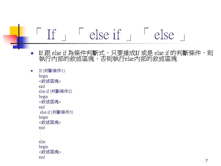
EX. Design Testbench (1/3) 注意顏色的對應,代表模組與模組的對應 n module testtech 1; // Inputs reg X; reg Y; reg Z; // Outputs wire F; // Instantiate the Unit Under Test (UUT) n tech 1 uut ( n n n Design Circuit module tech 1(X, Y, Z, F); . . endmodule n n . X(X), . Y(Y), . Z(Z), . F(F) n n n ); n initial begin // Initialize Inputs X = 0; Y = 0; Z = 0; // Wait 1000 ns for global reset to finish #1000 $finish; end n n n n 輸入觸發(up counter) n n always #5 X=X+1; always #10 Y=Y+1; always #15 Z=Z+1; endmodule Testbench module Switchlevel Gate level Dataflowlevel Behaviorallevel Call Design Circuit Module endmodule 23
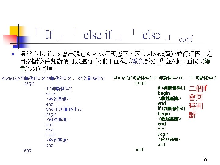
EX. Design Testbench (2/3) 輸入觸發(up counter) 輸入觸發(down counter) always #5 X=X+1; always #10 Y=Y+1; always #15 Z=Z+1; initial begin // Initialize Inputs X = 1; Y = 1; Z = 1; // Wait 1000 ns for global reset to finish #1000 $finish; end always #5 X=X-1; always #10 Y=Y-1; always #15 Z=Z-1; 24
EX. Design Testbench (3/3) 輸入觸發(user define) 輸入觸發(random) initial begin #5 X=0; Y=0; Z=0; #5 X=0; Y=0; Z=1; #5 X=0; Y=1; Z=0; #5 X=0; Y=1; Z=1; #5 X=1; Y=0; Z=0; #5 X=1; Y=0; Z=1; #5 X=1; Y=1; Z=0; #5 X=1; Y=1; Z=1; end always #5 X= $random; \沒有限制,隨機產生數據輸出 always #5 Y= $random%60; \有限制,隨機在-59~59間產生數據輸出 always #5 Z= {$random}%40; \有限制,隨機在 0~39間產生數據輸出 25
Question & Answer 26