Chapter 5 System Modeling 12 Yonsei University 2
 Yonsei University 2 nd Semester, 2014 Woo-Cheol Kim")


- Slides: 20
Chapter 5 System Modeling (1/2) Yonsei University 2 nd Semester, 2014 Woo-Cheol Kim
Topics Covered ± Context models ± Interaction models ± Structural models ± Behavioral models
System Modeling ± System modeling is the process of developing abstract models of a system, with each model presenting a different view or perspective of that system ± System modeling has now come to mean representing a system using some kind of graphical notation, which is now almost always based on notations in the Unified Modeling Language (UML) ± System modeling helps the analyst to understand the functionality of the system and models are used to communicate with customers
System Perspectives ± An external perspective, where we model the context or environment of the system ± An interaction perspective, where we model the interactions between a system and its environment, or between the components of a system ± A structural perspective, where we model the organization of a system or the structure of the data that is processed by the system ± A behavioral perspective, where we model the dynamic behavior of the system and how it responds to events
UML Diagram Types ± Use case diagrams, which show the interactions between a system and its environment ± Sequence diagrams, which show the interactions between actors and the system and between system components ± Class diagrams, which show the object classes in the system and the associations between these classes ± State diagrams, which show the system reacts to internal and external events
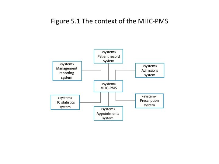
Context Models ± Context models are used to illustrate the operational context of a system – they show what lies outside the system boundaries ± Social and organizational concerns may affect the decision on where to position system boundaries
Interaction Models ± Modeling user interaction is important as it helps to identify user requirements ± Modeling system-to-system interaction highlights the communication problems that may arise ± Modeling component interaction helps us understand if a proposed system structure is likely to deliver the required system performance and dependability ± Use case diagrams and sequence diagrams may be used for interaction modeling
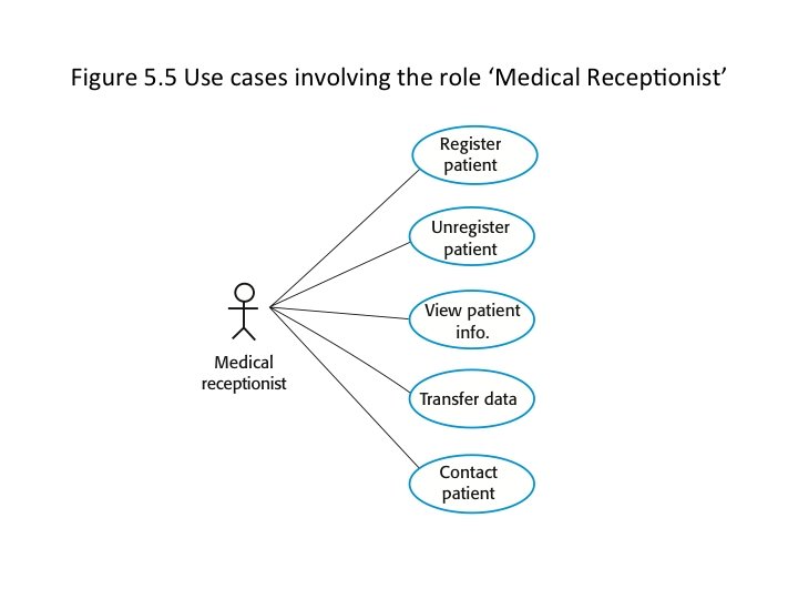
Use Case Modeling ± Use cases were developed originally to support requirements elicitation and now incorporated into the UML ± Each use case represents a discrete task that involves external interaction with a system ± Actors in a use case may be people or other systems ± Represented diagrammatically to provide an overview of the use case and in a more detailed textual form
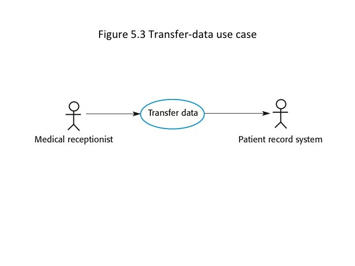
Tabular Description of ‘Transfer Data’ Use Case MHC-PMS: Transfer data Actors Medical receptionist, patient records system (PRS) Description A receptionist may transfer data from the MHC-PMS to a general patient record database that is maintained by a health authority. The information transferred may either be updated personal information (address, phone number, etc. ) or a summary of the patient’s diagnosis and treatment. Data Patient’s personal information, treatment summary Stimulus User command issued by medical receptionist Response Confirmation that PRS has been updated Comments The receptionist must have appropriate security permissions to access the patient information and the PRS.
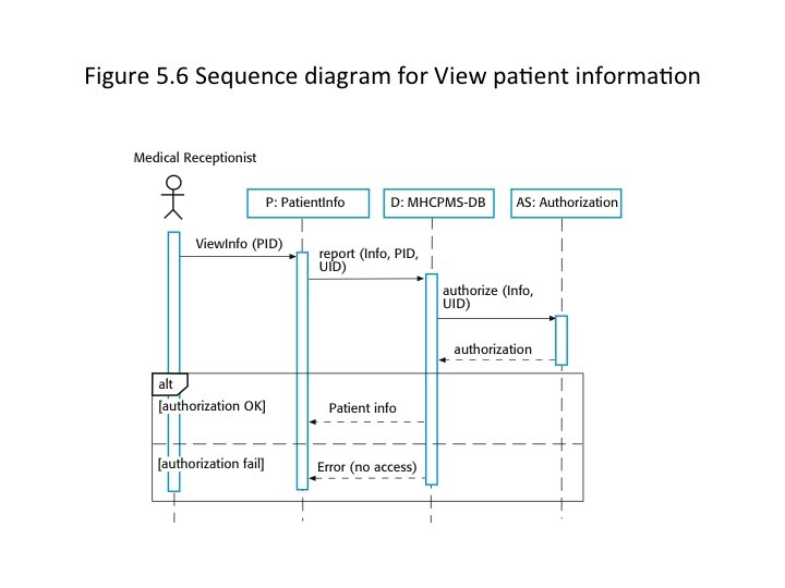
Sequence Diagrams ± Sequence diagrams are part of the UML and are used to model the interactions between the actors and the objects within a system ± A sequence diagram shows the sequence of interactions that take place during a particular use case ± The objects and actors involved are listed along the top of the diagram, with a dotted line drawn vertically from these ± Interactions between objects are indicated by annotated arrows
Sequence Diagram for View Patient Information ± The medical receptionist triggers the View. Info method in an instance P of the Patient. Info object class, supplying the patient’s identifier PID ± The instance P calls the database to return the required information, supplying the receptionist’s identifier UID to allow security checking ± The database checks with an authorization system that the user is authorized for this action ± If authorized, the patient information is returned and a form on the user’s screen is filled in. If authorization fails, then an error message is returned
Structural Models ± Structural models of software display the organization of a system in terms of the components that make up that system and their relationships ± Structural models may be static models, which show the structure of the system design, or dynamic models, which show the organization of the system when it is executing
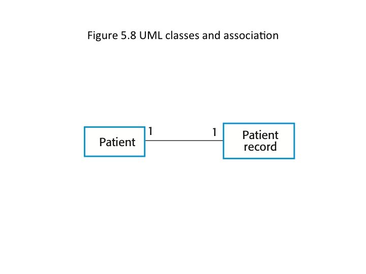
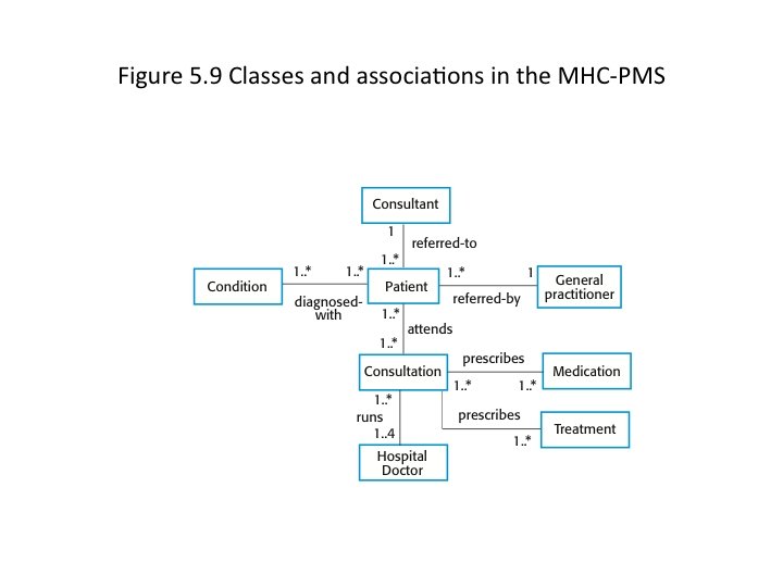
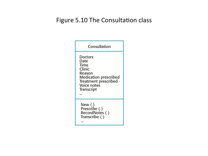
Class Diagrams ± Class diagrams are used when developing an objectoriented system model to show the classes in a system and the associations between these classes ± An object class can be thought of as a general definition of one kind of system objects ± An association is a link between classes, indicating that there is some relationship between these classes ± When we are developing models during the early stages of the software engineering process, objects represent something in the real world